
Forum Replies Created
-
AuthorPosts
-
 BRONZE Member
Danke @Die_Bogener!
Concerning foamrot, it’s no foam. I made a typo with the serial. This 8000 has serial 1711 xxxx. So a MKII, built with the new white foam.
I will check for copperline cracks and defect caps.
Any other ideas are welcome.
Location: The Netherlands
Favourite Product: BeoSound 9000
My B&O Icons:

The early models including your ser.nr. have been built with a type of foam that deteriorates after years of using the speaker. The foam then falls apart, sticks to traces on the PCB, components and connectors. Potentially causing shorts.
Did you open up the speaker casing, to have a look inside and see if the foam has deteriorated?
Location: The Netherlands
Favourite Product: BeoSound 9000
My B&O Icons:
22 June 2023 at 07:53 in reply to: BeoCenter 2300: where is the motion sensor for the doors located? #47238Exactly, I am also happy to understand the working of the motion detection on this B&o system.
Probably helpful to other BeoWorld members.
Location: The Netherlands
Favourite Product: BeoSound 9000
My B&O Icons:
22 June 2023 at 07:33 in reply to: BeoCenter 2300: where is the motion sensor for the doors located? #47236I did not expect these notches to be the receivers.
But this makes everything clear.
Thanks Guy!
Location: The Netherlands
Favourite Product: BeoSound 9000
My B&O Icons:
21 June 2023 at 10:23 in reply to: BeoCenter 2300: where is the motion sensor for the doors located? #47234Thanks Guy & Beobuddy!
So this is what I get from your info:
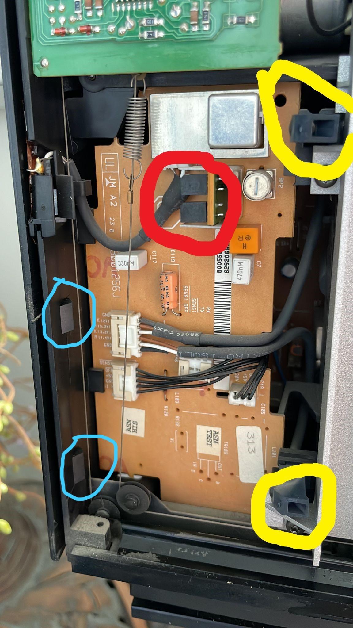
- There are 4 IR-transmitters, 2 on each side. In the picture they are marked yellow. For the left and right side they are placed symmetrically to each other.
- The IR-receivers look like the notch shape in the red marking, but are in a different location on the side.
Question
- Are there also 4 IR-receivers, 2 on each side?
- Are the IR-receivers the ones marked in light blue?
- If so, are the IR-receivers in the right side in the mirrored position to the ones in the left side?

Location: The Netherlands
Favourite Product: BeoSound 9000
My B&O Icons:
19 June 2023 at 10:50 in reply to: BeoCenter 2300: where is the motion sensor for the doors located? #47230Hi RaMaBo, thnx.
- The inwards pointing notch, is that the top one in the picture with the yellow markings?
- Does it mean one notch is sending light, and the other one is detecting reflection (a hand) of lhat light?
Location: The Netherlands
Favourite Product: BeoSound 9000
My B&O Icons:
19 June 2023 at 08:54 in reply to: BeoCenter 2300: where is the motion sensor for the doors located? #47228Thanks for sharing Guy!
I am helping a friend, so the BeoCenter 2300 is at a distance for me.
Anyhow, we found out that the sensors are in the black notches you marked with yellow.
They connect via two cables (with each three wires) into one connector. That’s the white connector in your picture with the two grey cables leading to it.What is not clear to me, but I am juyst interested to know …
I believe the sensor in the notches is a LED. So I assume the sensor works with sending and detecting light.
- So does motion detection for the doors work with a kind of light beam, and sensing the interruption by hand motion?
- Does the sensor/LED send the light to the side from underneath the black panel? (So not straight forward, because the black panel covers the notch)
Location: The Netherlands
Favourite Product: BeoSound 9000
My B&O Icons:
7 June 2023 at 15:55 in reply to: BeoLab 8000: request for very first version of the Service Manual #47041Thnx for this addition Keith.
You are right: the tracks are different, components are in different locations or positioned in a different direction, …
I hope someone has the right version of the service manual, with a diagram reflecting the pcb in the photo picture.
Location: The Netherlands
Favourite Product: BeoSound 9000
My B&O Icons:
Thanks again Keith. Very much appreciated you are still willing to help me!
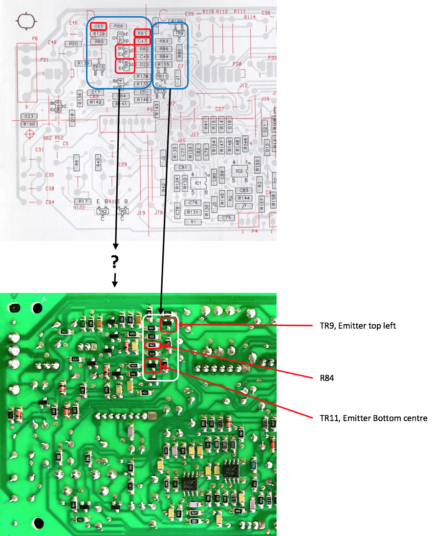
After having returned from abroad after a few weeks, I have immediately started testing what you suggested in your last message. I listed 7 components from your suggestion and picture, to be tested on a GND connection with the multi meter: TR9, R84, TR11, R81, C47, C65, TR7, TR8. I used the visual layout of the board in the service manual (see top part of picture below), to find the exact location of these components.
Here’s the results
First of all I could find TR9, R84 and TR11. Their location according to the visual layout in the Service manual and the PCB itself, was identical. These are the findings on these components:
- P7-2 <> TR9 Emitter = Yes, continuity
- P7-2 <> R84 = Yes, continuity
- P702 <> TR11 Emitter = No continuity on the Emitter, but Yes continuity on the Collector
With the other 4 components I found out that the visual layout from the service manual, and the actual layout of the board differ. So for them I am unsure what their location on the board is.
In the picture below you will see both layouts. In the top image I have marked the 4 components that I can’t match with the layout of the PCB. In the bottom image I have marked the 3 components I could find and which I tested.
Speaker info- Type number = 6801 (B)
- Serial number = 1448 8372
Comments / questionsMaybe the results of the 3 tested components already give you a clue. Is TR11 malfunctioning and the cause?
What do you suggest?

Location: The Netherlands
Favourite Product: BeoSound 9000
My B&O Icons:
Thanks a lot, perfect.
Yes, with the dimensions that are known and your pictures, I can estimate all other dimensions. That will work.
Location: The Netherlands
Favourite Product: BeoSound 9000
My B&O Icons:
I am not sure about the exact serial number at which B&O changed the foam type.
I can tell that the highest serial number in which I have seen ‘old’ foam, was serial 154x xxxx.
Maybe someone knows this more precisely.
Location: The Netherlands
Favourite Product: BeoSound 9000
My B&O Icons:
Thnx very much Lausvi.
you are completely right. I wanted to see the interior. And as I haven’t had my hands on this BeoVox type yet, I wasn’t aware that the back panel had to be removed to get there. So thanks for understanding that.
If I may ask …
In picture 1 and 2, the two pieces of white foam van be seen on the right.
What are the dimensions of both pieces? (W x L x D)
Location: The Netherlands
Favourite Product: BeoSound 9000
My B&O Icons:
Thanks Keith!
I am away currently.
When I am back, I will continue making your suggested checks.
Location: The Netherlands
Favourite Product: BeoSound 9000
My B&O Icons:
Thnx Keith!
Here’s a response to all things you mentioned.
(1)
When you use the multi-meter which triggered the relay and you heard music, did the LED go green?Yes, the LED goes green, and the speaker plays music.
(2)
In the last post where you measured 52 volts was that with signal connected to the RCA socket?Yes, it measures 52 volts when a (playing) audio signal is connected to the RCA socket.
Though, it also measures 52 volts when nothing is connected to the RCA socket.Curious to hear what you think of this.
Location: The Netherlands
Favourite Product: BeoSound 9000
My B&O Icons:
Thanks Keith, have a safe trip!
Reading back, I noticed you mentioned this:
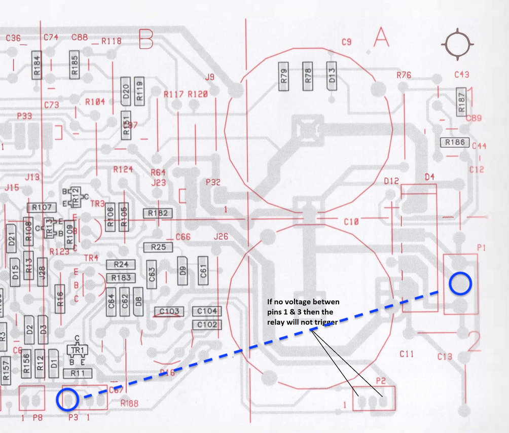
The negative end (plug 3 pin 1) of the D1 diode is directly driven from the “Auto Start” circuit which takes your source input on the RCA socket. You could therefore also test between plug 3 pin 1 and plug 1 pin 2.
And I did not measure that yet. So here’s about that:
- I measured between the two pins as marked in the picture below.
- The measured value is 52 volts.
Hope you have a recommendation for a next step.

Location: The Netherlands
Favourite Product: BeoSound 9000
My B&O Icons:
Update
The problem with the BeoLab 8000, not switching from stand-by to On (red to green LED), still persists.
PowerLink test
Since I temporarily have a BeoSound 9000 at hand, I decided to test the BeoLab 8000 on its PowerLink connection.Result
When connected via PowerLink, this BeoLab 8000 switches smoothly from stand-by to On. So this works in normal operation.Question
I assume, there is something wrong with the auto-start and RCA combination.
Please advise, what I can do next?Location: The Netherlands
Favourite Product: BeoSound 9000
My B&O Icons:
@Keith
What do you think after my last measurements?
Suggestions welcome.
Location: The Netherlands
Favourite Product: BeoSound 9000
My B&O Icons:
I am working on a similar situation. Have a look at this thread. Hope it helps.
Location: The Netherlands
Favourite Product: BeoSound 9000
My B&O Icons:
Thnx Beobuddy.
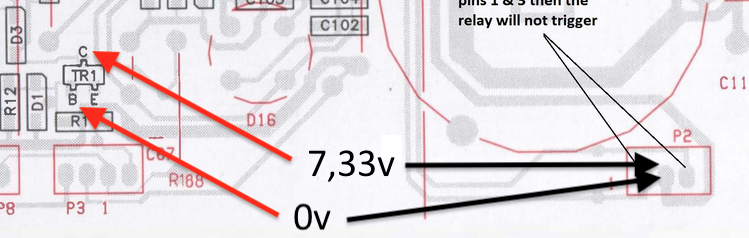
FYI, the multimeter I am using is a Voltcraft VC130-1.So I measured between TR1 and GND/pin 2 on P2, while having power on the BeoLab 8000. So it’s in standby mode, red LED on. Here’s the results:
- TR1 Base <> Pin 2, P2 = 0 volts
- TR1 Collector <> Pin 2, P2 = 7,33 volts

What do you think BeoBuddy, what could be the underlying cause?
Location: The Netherlands
Favourite Product: BeoSound 9000
My B&O Icons:
-
AuthorPosts