
Forum Replies Created
-
AuthorPosts
-
 BRONZE Member
That’s a wonderful result Shmoo!
And great that you share the result of your attempt. That helps the community!
Enjoy your masterpiece BeoSound 9K
Location: The Netherlands
Favourite Product: BeoSound 9000
My B&O Icons:

Sure.
In my case the slower movement of the CD-sledge had to do with ‘the system thinking’ that the glassdoor isn’t closed. If the system concludes that, it forces to slower sledge speed as a protection (cause if fingers are near, a sledge at high speed becomes a guillotine).
What did the trick for me was having proper functioning glass door sensors.
I cleaned the two prisms with IPA and eartips. And I cleaned the aluminum surface underneath the glassdoor and the glassdoor itself with IPA.
I hope it works for you too.
Location: The Netherlands
Favourite Product: BeoSound 9000
My B&O Icons:
Ik zou het vriendelijk formuleren, maar hem wel adviseren om vóór een volledige recap eerst nog een paar gerichte metingen te doen.
That is good news regarding the original CD problem, but I would personally hesitate before replacing all ~30 capacitors on PCB32.
The fact that CD audio is now perfect through the headphone output suggests that the original CD/DAC audio problem has actually been solved.
The remaining problem now seems much more specific: CD audio is present through Master Link, but at a very low level.
Before doing a complete recap, I think a few checks could help narrow this down:
- Which capacitor did the technician replace to solve the original problem? Its value, location and what circuit it is connected to would be very interesting, especially since it is apparently not shown in the MK3 service manual.
- Does RADIO still play at normal volume through Master Link while CD is very quiet?
- Is the low CD volume the same through both the BeoVision 7 and BeoSound 5?
- Can the technician trace the CD audio signal from the now correctly functioning CD/DAC section towards the Master Link circuitry and find where the signal level drops?
Especially if RADIO has normal volume through the same Master Link connection while CD is very quiet, that would suggest that the Master Link connection and at least much of its circuitry are working correctly.
I would therefore try to locate where the CD signal loses amplitude before replacing every capacitor.
There has already been quite a lot of rework on PCB32, and replacing another 30 SMD components on a multilayer board also introduces some risk of damaged pads, vias or new soldering problems.
So my preference would be: diagnose first, then replace components selectively.
And please let us know which mysterious capacitor finally solved the original problem — that may be one of the most useful findings from this whole repair!
Location: The Netherlands
Favourite Product: BeoSound 9000
My B&O Icons:
This is actually a very significant new observation.
The behaviour has changed from:
“the sound disappears after some time”
to:
“there is no sound at first, but if I let the CD continue playing, the sound appears after a few minutes and then remains stable.”
To me, that points much more towards a temperature-dependent analogue circuit than a CD reading or source selection problem.
The fact that:
- the CD is recognised immediately,
- the time counter runs correctly,
- tracks can be changed,
- Radio works normally,
- switching Radio → CD does not restore the sound,
- but simply waiting does,
suggests that some part of the audio circuitry only starts working once it has warmed up.
At this stage I would try the opposite of freeze spray.
Instead of cooling components, I would carefully warm individual suspect components or small areas (for example with a hot air station set to a low temperature or a hair dryer from a safe distance).
If warming a specific component causes the sound to appear much sooner, that would be a very strong clue.
I would start with the area around the LF33CDT, TR405 and the surrounding analogue circuitry on PCB32, since that area has already shown temperature sensitivity during your earlier tests.
One additional thought: although the LF33CDT has been replaced, I would still verify the 3.3V rail with an oscilloscope during the first few minutes after power-up. Since the earlier thermal tests pointed to this area, it would be useful to confirm that the regulator output is not showing excessive ripple, oscillation or instability while the unit is warming up. It would also be worth carefully inspecting the solder joints and nearby components around the replacement regulator.
Location: The Netherlands
Favourite Product: BeoSound 9000
My B&O Icons:
Thank you for the update.
Actually, I think this gives us another important clue. The fact that you were able to play two complete CDs without any problems strongly suggests that the laser and CD mechanism are fundamentally working correctly.
When the fault occurs:
- the CD is recognised,
- the disc spins,
- the time counter advances,
- you can change tracks and even change CDs,
- but there is simply no audio.
To me, this now sounds less like a CD reading problem and more like an audio routing, muting or initialization issue.
I have one question that may help narrow it down further: When CD is playing with no sound, could you try the following?
- Switch to RADIO and confirm that radio audio is present.
- Then switch immediately back to CD.
Does the CD audio return, or does it remain silent?
If switching sources restores the CD audio, that would point towards a source selection or muting problem.
If the CD remains silent even after switching back from RADIO, then we should continue looking around the CD audio path on PCB32.
I think this simple comparison could provide a very useful clue.
Location: The Netherlands
Favourite Product: BeoSound 9000
My B&O Icons:
Thank you, that is important information.
I also have another thought.
A worn laser in a Beosound 9000 usually causes problems reading the disc itself. In that case, you would typically expect symptoms such as difficulty reading the TOC, long “Reading…” times, failure to start playback, or skipping during playback.
However, in your case the CD appears to be recognised correctly, the counter starts normally, and the disc continues playing.
That seems to suggest that the digital data is being read successfully, making a laser problem less likely.
Can you confirm one detail?
When there is no sound, does the time counter still continue to advance normally from 00:00 as if the CD is playing correctly?
If the answer is yes, I think that points even more towards a problem after the data has already been read from the disc, rather than a laser or optical pickup issue.
I still think the key is to compare the “sound OK” and “no sound” situations and determine exactly what changes between those two states.
Location: The Netherlands
Favourite Product: BeoSound 9000
My B&O Icons:
Great!
Out curiosity:
– Which one?
– Picture?
Location: The Netherlands
Favourite Product: BeoSound 9000
My B&O Icons:
That is an interesting observation, but I am not yet convinced that it is directly related to the CD audio problem.
To me, it sounds more like a separate issue involving the sledge positioning or calibration.
If TM71 always fails because the sledge crashes into the disc in position #2, I would first suspect:
- incorrect home/reference position,
- sledge position feedback (sensor or encoder),
- mechanical alignment,
- or a servo control issue.
The important question is:
Did this behaviour already exist before replacing the LF33CDT, or is this the first time TM71 has been run?
If TM71 has never completed successfully, it may simply be revealing a second, unrelated fault.
On the other hand, if this behaviour only appeared after the recent work, it would be worth checking whether anything around PCB32, its connectors or the servo-related signals has changed.
For now, I would treat the TM71 failure and the intermittent CD audio as two separate problems unless there is clear evidence that they are connected.
Location: The Netherlands
Favourite Product: BeoSound 9000
My B&O Icons:
Sorry to hear that Edo. The new symptoms actually make the diagnosis even more interesting.
The fact that:
- the CD spins correctly,
- the counter advances normally,
- radio always works,
- and sometimes switching to Radio first and then back to CD restores the sound,
suggests to me that this may no longer be a simple thermal failure.
I now wonder if there is an initialization, muting or power sequencing issue on PCB32.
The replacement of the LF33CDT may have improved the original thermal problem, but there could still be another fault in the same area.
I think it would be useful to compare two situations:
- Cold start → select CD → no sound.
- Cold start → select Radio → then switch to CD → sound OK.
In both cases I would check:
- Is the analog audio present at the output of the TDA1305T?
- Is the 3.3V output of the LF33CDT stable (preferably with an oscilloscope, not only a multimeter)?
- Does the muting circuit behave differently between the two cases?
I would also carefully inspect and, if necessary, reflow the solder joints around the LF33CDT, its input/output capacitors, nearby vias and connectors. A marginal solder joint or via could easily explain why the behaviour changes after source switching.
The good news is that the investigation now seems to be focused on a much smaller area than before.
Location: The Netherlands
Favourite Product: BeoSound 9000
My B&O Icons:
I do not recognitie it as a B&O part, but it might still be one. Looks to me as something that is to be pushed in some kind of frame (with the 4 upstanding feet). And keep two cables/wires apart from each other on both sides.
If you have some extra pictures from different angles, my Ai-part finder might help.
Location: The Netherlands
Favourite Product: BeoSound 9000
My B&O Icons:
Hi Martin,
Can you upload mor pictures, of all sides?
And add the dimensions?Best,
ErnstLocation: The Netherlands
Favourite Product: BeoSound 9000
My B&O Icons:
That is excellent news! Congratulations on finding the real fault.
This has turned out to be a very interesting troubleshooting case.
In hindsight, the LF33CDT explains many of the symptoms. A regulator can become thermally unstable without completely failing, so measuring a nominal voltage with a multimeter does not necessarily mean the supply is healthy. Small voltage dips, oscillation or excessive noise can easily upset the DAC and surrounding circuitry.
I think your systematic approach deserves credit:
- Verifying the digital signals,
- Replacing the suspected DAC,
- Using thermal testing,
- And finally narrowing the fault down with freeze spray.
Thank you for taking the time to report the final solution. Threads like this become very valuable for other Beosound 9000 owners who may encounter the same problem in the future. Great info for the community!
Enjoy your rescued & fully working BS9000!
Location: The Netherlands
Favourite Product: BeoSound 9000
My B&O Icons:
Thanks for sharing again Edo. This is actually the most promising clue so far.
What caught my attention is that cooling the LF33CDT does not just bring the sound back temporarily, but appears to extend the operating time before the fault occurs. That makes the LF33CDT a much stronger suspect than the components investigated earlier.
Since the LF33CDT is a 3.3V regulator, a thermal problem there could potentially explain many of the symptoms observed so far, including why the DAC initially appeared to be the culprit.
If I were troubleshooting this, I would not only replace the LF33CDT, but also:
- Inspect and reflow its solder joints,
- Measure its input and output voltages before and after the fault,
- Monitor the 3.3V rail while the unit warms up,
- Check whether the output voltage changes when the regulator is cooled.
At the moment, this seems like the strongest lead you have had so far. Please keep us updated after the replacement.
Location: The Netherlands
Favourite Product: BeoSound 9000
My B&O Icons:
Great to hear you have practical helping hands to support you. Good for you!
For the interest of others reading this topic, please come back when your issue has been resolved. And ask your friend to write a short summary of the cause and how he solved it.
Location: The Netherlands
Favourite Product: BeoSound 9000
My B&O Icons:
Thank you, the photos help understanding.
A few things are still unclear to me:
- During your test with the Pioneer headphone output, approximately where was the volume control set?
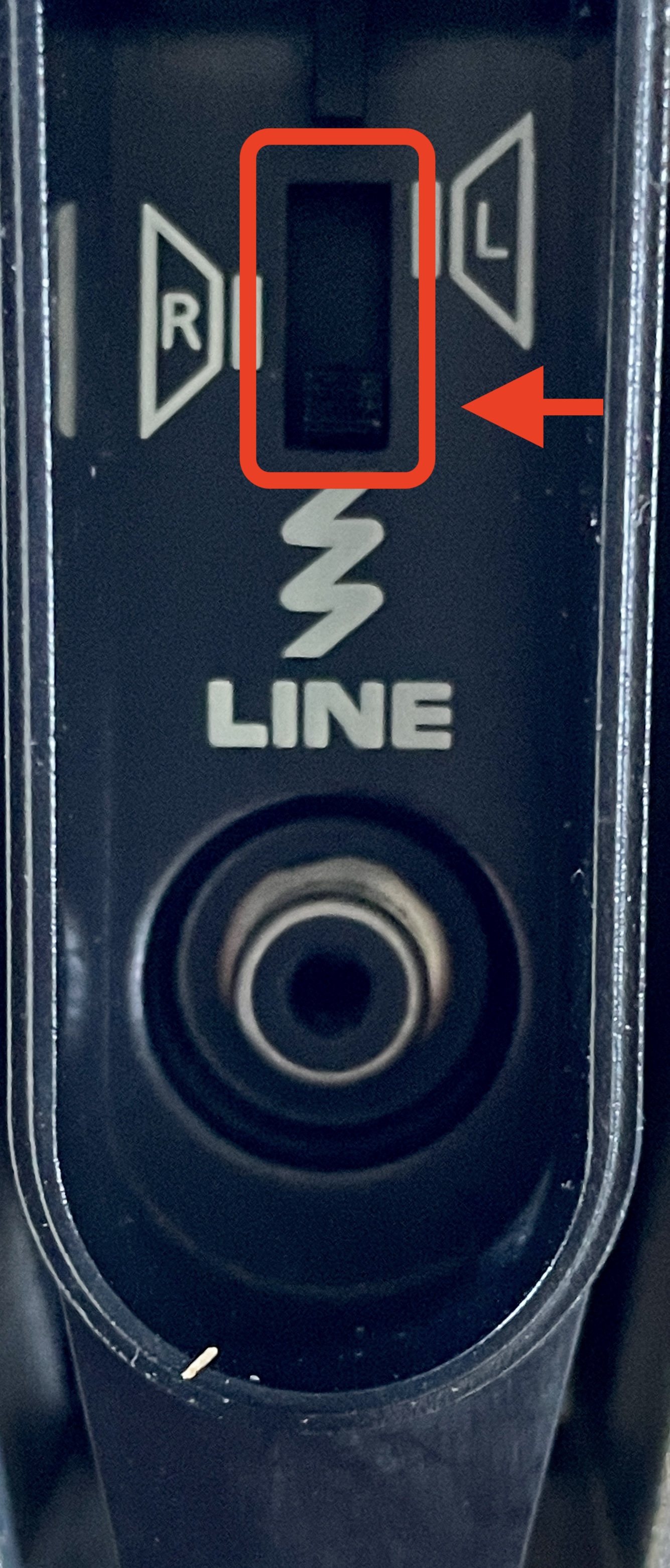
Very low, medium, or normal listening level? - For your tests, did you put the small switch on the bottom of the BeoLab 8000, to the lower position (LINE – see picture) when using the RCA input: yes/no? (The speaker may not work correctly from the RCA input when the switch is in the PowerLink position)
- Can you connect the working BeoLab 8000 using exactly the same setup:
- same Pioneer amplifier
- same cable
- switch in the lower (LINE) position
- same volume setting
- Can you share the results of this check?
- Also, when the faulty speaker LED is green, do you hear absolutely nothing at all?
No hiss from the tweeter, no hum, no clicks from the drivers?
This information will help narrow the fault down considerably.
Location: The Netherlands
Favourite Product: BeoSound 9000
My B&O Icons:
Hi Christian,
One important question that may help us narrow this down: How exactly are you testing the speaker?
Are you using:
- PowerLink from a B&O source?
- The RCA input?
- Something else?
You mentioned that the LED turns green when you power the speaker on. Does it also stay green while music is actually playing?
Knowing how the speaker is being driven is important, because it helps us determine whether the amplifier is receiving an audio signal at all, or whether we should focus on the audio input stage first.
The fact that the LED goes green and the relay clicks is still encouraging, as it suggests that a large part of the electronics is functioning normally.
Location: The Netherlands
Favourite Product: BeoSound 9000
My B&O Icons:
Thanks Christian, for posting the photos.
I don’t immediately see any obviously burnt components, damaged tracks or leaking capacitors, which is hopeful. Before measuring anything complicated, can you tell us exactly what the speaker does? (When connected via PowerLink/Line-IN and starting music):
- Does the LED stay red permanently?
- Does it change from red to green when a signal is present?
- Do you hear any clicks from inside the speaker, when music is started?
- Does the other speaker still work normally?
Let us know your findings.
Location: The Netherlands
Favourite Product: BeoSound 9000
My B&O Icons:
Hi Christian,
The fact that the red LED still comes on is actually encouraging. If the main fuse had completely blown, I would normally expect the speaker to be completely dead.
Since the speaker was accidentally connected to 220V while still configured for 110V, I suspect the standby power supply may still be working, but another part of the power supply could have been damaged.
My suggestion would be to start with the basics:
- Check the mains fuse with a multimeter (power disconnected).
- Post clear photos of both sides of the power supply board.
- If you are comfortable using a multimeter, measure the secondary supply voltages coming from the power supply.
Also, did you hear a pop, smell anything burning, or see any smoke when it happened? And does the other speaker still work normally?
Those details may help narrow down the fault considerably.
Good luck, and don’t give up on them yet — the fact that the LED still lights up is a positive sign.
Location: The Netherlands
Favourite Product: BeoSound 9000
My B&O Icons:
I would not worry too much about the 4-layer PCB at this stage.
Yes, an internal track or via failure is possible on a multilayer board, but based on the symptoms I do not think it is the most likely explanation yet.
The reason is that you already have several strong clues pointing towards a localized thermal issue:
- cooling around C401/C403 restores the sound,
- replacing C401/C403 did not solve the problem,
- TR405 starts oscillating when the fault occurs,
- the behaviour is repeatable and temperature-dependent.
To me, that still sounds more like a component, solder joint, via, regulator, transistor or local control circuit problem than a hidden internal PCB track.
I would wait for the proper freeze spray and continue narrowing down the exact area by cooling individual components one at a time.
In particular, I would focus on:
- TR405,
- components directly connected to TR405,
- nearby capacitors, resistors and diodes,
- and any ICs or regulators in the same section of PCB32.
Only if the freeze spray testing fails to identify a specific component or area would I start considering an internal PCB defect as a more likely possibility.
At this point I still think there is a reasonable chance that the actual fault can be isolated and repaired.
Location: The Netherlands
Favourite Product: BeoSound 9000
My B&O Icons:
Hi Edo, thanks for your update.
I actually think this is progress. The fact that replacing the TDA1305T did not change the behaviour strongly suggests that the DAC itself was not the root cause. What I find more interesting is that:
- cooling around C401/C403 restores the sound,
- replacing C401/C403 did not solve the problem,
- and TR405 starts oscillating when the audio disappears.
That makes me wonder whether C401/C403 are simply close to the actual faulty component, rather than being the fault themselves.
At this point I would focus on TR405 and the components directly around it. It may be useful to measure the base, collector and emitter voltages of TR405 before and after the fault occurs.
Once the freeze spray arrives, I would also try cooling TR405 and the surrounding components individually rather than cooling a larger area of the PCB. To me, TR405 and its local circuitry now look like stronger suspects than the DAC.
Location: The Netherlands
Favourite Product: BeoSound 9000
My B&O Icons:
-
AuthorPosts