
Forum Replies Created
-
AuthorPosts
-
 BRONZE Member
Of course, I understand its Steve’s business. 🙂
But I do not have to know how the cable has been configured internally.I just want to understand if this is only a Mini-Jack-to-DIN cable …
Or that it comes with something else for the 5-volt/trigger signal.@Steve: maybe you like to respond to this?
Location: The Netherlands
Favourite Product: BeoSound 9000
My B&O Icons:

@Steve
Very interesting the Mini-jack to RCA cable also has a trigger signal.
But for my understanding, the trigger signal needs to be 5v on Pin 4.
Where do you get the 5v to be used on Pin 4 to activate the B&O speaker amp to get from stand-by to active? Hoe does that work with this cable?
Location: The Netherlands
Favourite Product: BeoSound 9000
My B&O Icons:
Did you connect a Powerlink or RCA cable to one of the connectors?
what do you see and hear when you do that?
Location: The Netherlands
Favourite Product: BeoSound 9000
My B&O Icons:
@Steve
Great comment Steve.
How does the (for instance) Apple Airport generate a trigger signal for the BeoLab?
By the way. Is it possible to see the linked product when your website is temporarily closed?
I understand your not 24/7 available to follow-up on everything. Though I can imagine that you keep all informative parts of your website accessible, and close ordering and contact form. Would that work for you?
Location: The Netherlands
Favourite Product: BeoSound 9000
My B&O Icons:
Hi Lawso,
1) What do you prefer; a) to have an external device to add streaming capabilities, or b) an internal integrated solution?
2) To which B&O model would you like to add these capabilities?
Location: The Netherlands
Favourite Product: BeoSound 9000
My B&O Icons:
Thanks for your replies guys!
I mainly wanted to know if the pin 3 & 5 and pin 2 & 4 would work simultaneously. So thanks for confirming.
Concerning the cable … the one I need will look a little bit different. I need to split from DIN to a) mini-jack and b) RCA female. But that’s no issue for me, to make one myself.
Location: The Netherlands
Favourite Product: BeoSound 9000
My B&O Icons:
Why I would do so > Cause I need the turntable and the cassette deck connected to the BeoSound for both recording, as well as for playing via speakers connected to the BeoSound.
Is it possible to simultaneously:
- Connect a turn-table via the Auxiliary Pin 3 & 5 and play vinyl
- And connect my cassette-deck via the same Auxiliary Pin 2 & 4 and record the music from the turn-table
Comment: I would say so, cause normally with RCA connections this AUX would be two RCA connectors for Line IN, and two RCA connectors for Line OUT. So, isn’t the DIN a combination of these sets of RCA connectors in one plug?
Question
Please comment on my ‘Is it possible to simultaneously …’ question.
Location: The Netherlands
Favourite Product: BeoSound 9000
My B&O Icons:
So here’s an additional question …
Is it possible to simultaneously:
- Connect a turn-table via the Auxiliary Pin 3 & 5 and play vinyl
- And connect my cassette-deck via the same Auxiliary Pin 2 & 4 and record the music from the turn-table
Is this possible?
(Assuming of course that a made a splitter cable which can handle that)
Location: The Netherlands
Favourite Product: BeoSound 9000
My B&O Icons:
Thnx to all, this is a great experience to have such great responses so quickly on the BeoWorld forum!
Additionally I should mention, the external recorder is non-B&O. It will be a vintage Nakamichi 600 cassette deck.
Not being able to control this external recorder as a B&O device is not an issue. For me it is just important that there is a L & R channel OUT, that I can pick up via the Auxiliary connector on the back of the BeoSound 3200.
So from all your information I conclude it is possible and will work. As long as I use:
- Pin 1 > Left out
- Pin 2 > GND
- Pin 4 > Right out
As mentioned and described in the response and picture of Matador.
Thanks!
Location: The Netherlands
Favourite Product: BeoSound 9000
My B&O Icons:
Hi Cavscout,
How sure are you that the leads in your cable(s) are connected to the right pins?
Do you have a scheme of the connections, and where did you buy them? (Did you contact Steven from SoundsHeavely?)Location: The Netherlands
Favourite Product: BeoSound 9000
My B&O Icons:
Thanks for your extensive response and guidance. This is very helpful!
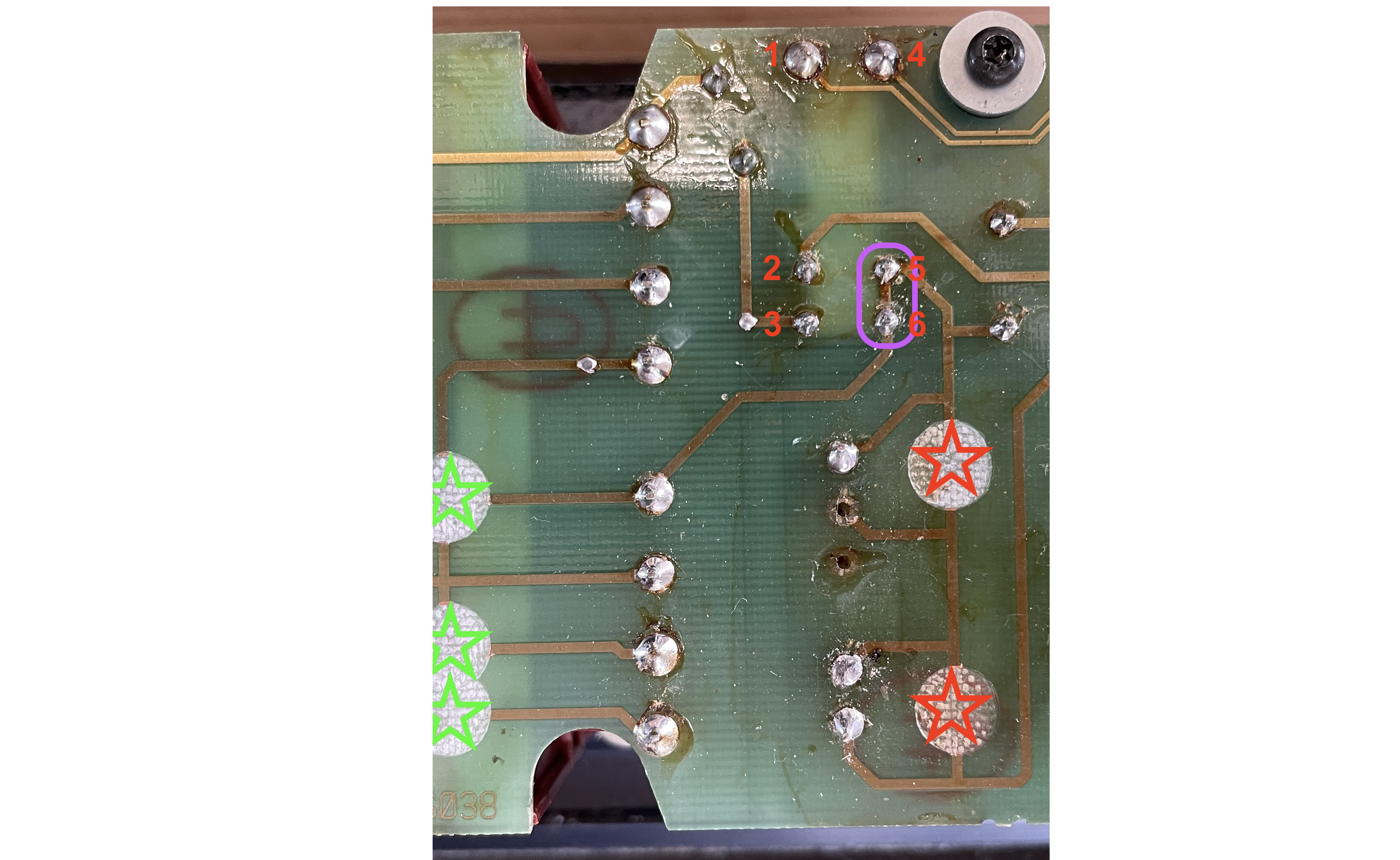
Some clarification questions from my side.- For checking the 23v DC at the relay coil … I believe it has 6 pins. Which ones should I use to measure on?
- You mentioned it possible for the Relay RL1 to stick open. What should I (not) measure when it is stick open? And at which pins should I do the measurement?
For reference, I added a picture showing the bottom of the PCB and the relay pins with numbers.

Location: The Netherlands
Favourite Product: BeoSound 9000
My B&O Icons:
It’s gonna be stereo to mono.
In this case I am not going to link two speakers to a stereo set.Location: The Netherlands
Favourite Product: BeoSound 9000
My B&O Icons:
@Pilatomic: thnx!
In the meantime I ordered the Taco TMR 4-4811WI, and I have been able to make a test setup with all connected. This is what happens.
When I turn the system on:
- C5 +/- measure 35v, so that’s fine.
- The Taco output measures +/- 5v, so also fine.
Which means, when I plug in power on the BeoLab 6000, my wireless module gets 5v, and starts booting. Streaming music also works fine after the booting.
Problem
When I stop streaming music, the BeoLab switches back to stand-by (Green LED becomes Red).
But at that moment, the voltage coming from C5, drops from 35v to 30v. This causes the wireless module to reboot, which causes the auto stand-by switch back on (Red LED becomes Green).
Which means, this situation creates a loop. Every time music is stopped, the BeoLab returns to stand-by, which causes voltage drop and the wireless module to reboot, …. and so on.
Question
Maybe C5 is not the right point to take the voltage from.
- Is there any other point where the DC voltage is always available (also in stand-by mode (Red LED), and in a constant voltage?
- Where?
Location: The Netherlands
Favourite Product: BeoSound 9000
My B&O Icons:
Thnx Matador!
Concerning your PSU suggestion …
This is how I started, but I have had some issues with it. Adding a AC/DC converter that connects to the same power source as the BeoLoab 6000 itself, can cause disturbed audio signals. Many AC/DC converters work, but because they are switching PSU’s, they can cause ‘Ripple’ disturbances.
Therefor, I think an added wireless module can better be powered with DC voltage from the BeoLab 6000 system. This will be much cleaner.
Can you help me understand where such DC points on the PCB can be found, or do you know someone who can?
Location: The Netherlands
Favourite Product: BeoSound 9000
My B&O Icons:
@Damiendada
Do you mean, you are also looking for voltage points?
Location: The Netherlands
Favourite Product: BeoSound 9000
My B&O Icons:
So if I understand right, you put an MK2 amp in a MK1 housing right?
Location: The Netherlands
Favourite Product: BeoSound 9000
My B&O Icons:
I assume you took the old foam out and that you had to clean the remains from foam rot?
If that is the case, you can check if some of the copper traces on the PSU PCB have been damaged by the foam rot. Sometimes you need a magnifying glas to see it, but then you might detect copper traces partly ‘eaten away’ by foam rot. If you have such a thing, you can solder a wire as a kind of by-pass.
Also check if there is still foam rot remains on connectors or components. And check if there are components that are damaged, like for instance capacitors that look puffy.
What is the serial number / production year?
Location: The Netherlands
Favourite Product: BeoSound 9000
My B&O Icons:
Thnx Matador!
I am gonna use a small external Bt-antenna. Wire goes external via bottom to foot plate.But can you help find a DC voltage in the BeoLab 6000 that would work for me?
Location: The Netherlands
Favourite Product: BeoSound 9000
My B&O Icons:
Dear Warrima,
What brand and type of CD player did you connect to the BeoSound?
Location: The Netherlands
Favourite Product: BeoSound 9000
My B&O Icons:
Well I can only say that I have made a custom cable (mini-jack > DIN), that connects to the right pins of the MasterLink connection on the BeoLab 3500.
Since what I connect, is not a B&O device, the MasterLink will not automatically ‘sense’ that an audio source wants to play via this connection.
So to activate the MasterLink as an audio input, I use the BeoLink remote to switch to the ML-input, by pressing this sequence: “Menu > Menu > 0 > 3 > Go”The BeoLab than goes to the MasterLink input and my music plays. So everything does work, but I find the sequence one has to handle on the BeoLink, nut very user friendly. That’s why I am looking for an easier way to get the BeoLab 3500 to be activated on the ML input much easier.
- Preferably because it goes to the ML input when switched on.
- Or by pressing button to activate a kind of macro for the earlier mentioned sequence.
Any ideas, suggestions welcome again! 🙂
Location: The Netherlands
Favourite Product: BeoSound 9000
My B&O Icons:
-
AuthorPosts