


Home › Forums › Product Discussion & Questions › BeoLab › BeoLab 8000: dead / no red LED, measurements attached
- This topic has 20 replies, 4 voices, and was last updated 2 years, 5 months ago by
 prorsum.
-
AuthorPosts
-
28 March 2023 at 05:11 #45037
 BRONZE Member
I have a BeoLab 8000 that is dead with power attached: no red LED.
It has serial number 14xx, and yes it had foam rot. I have cleaned all electronics, connectors, etc. Also I have done some checking & measuring:
On the PSU PCB, I have done continuity measurements, and found no faults.
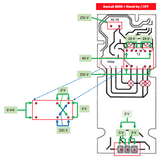
Also I have measured all voltages, the result is visible in the picture attached.- AC in is fine, and voltages on both sides of T2/stand-by transformer are ok.
- On the output side of the PSU PCB, the voltages are zero volts.
The Relay shows voltages that I think are not OK. What probably explaines why the voltages on the output side are zero.
Question:
- Is this just a matter of a broken Relay, or is something else going on?

Location: The Netherlands
Favourite Product: BeoSound 9000
My B&O Icons:
 29 March 2023 at 16:01 #45038
You show in your diagram that T2 between pins 7 & 12 is at 231 volts.
The T2 relay will NOT trigger if there is no AC voltage on Pins 1 & 3 of Plug 2 on the power supply.
If there is really zero volts between pins 1 & 3 of plug 2 on the power supply, then either you have broken PCB track between the T2 transformer pin 7 and plug 1 pin 1 OR broken track between T2 pin 12 and plug 1 pin 3 OR pin 9 & 10 on T2 are not connected.

Location: Hampshire, England
30 March 2023 at 13:34 #45039Thnx Keith!
I measured the voltage between pin 1 & 3 of P2 = 44 volts AC
Just to be sure, I also measured continuity:
- T2 pin 7 > plug 1, pin 1 = OK
- T2 pin 12 > plug 1, pin 3 = OK
- T2 pins 9 & 10 = OK
Knowing this, what do you think is wrong?
Location: The Netherlands
Favourite Product: BeoSound 9000
My B&O Icons:
30 March 2023 at 19:12 #45040Well, it is excellent that you have 44 volts between pins 1 & 3 of plug 2
So, the fault is either going to be one of the following:-
- The 24 volt relay itself is faulty, less likely, but possible
- The D1 diode across the relay coil is short circuit
- The + 15 volts is missing from the emitter of Tr3
- The – 15 volts is missing from the emitter of Tr4
- The “auto start” circuit used when using phono socket is enabled has a fault.
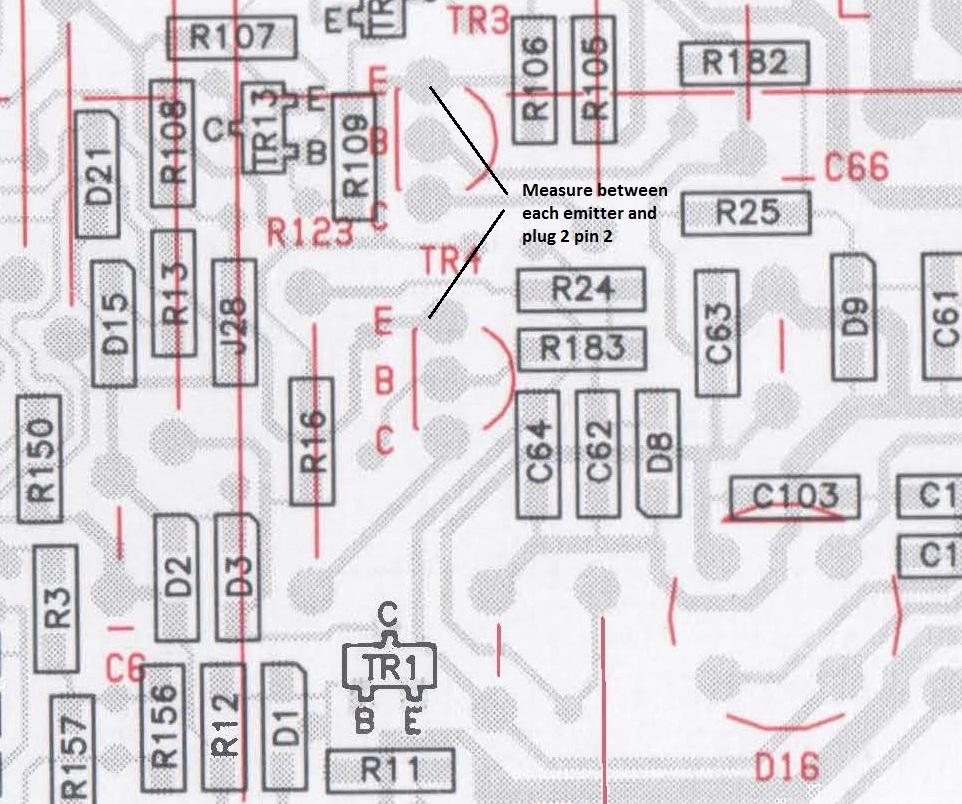
Check points 3 & 4 first by measuring between a ground point such as Plug 2 pin2 and the emitter of Tr3 (+15 volts) and then Tr4 (-15 volts)
Measure the voltage between pins 1 & 2 of plug 3 on the power supply module
If +15 and -15 volts are correct, but there is zero or near to zero volts between pins 1 & 2 of plug 3 then the “auto start” circuit may the cause.

Location: Hampshire, England
31 March 2023 at 21:43 #45041Thanks a lot Keith!
Red LED is ON again
First of all, after my last checks I put the PSU/AMP-block back into the speaker casing, and connected everything back to original.
Surprisingly, the red LED went ON again! So that’s good. Obviously I also checked if it would respond to an audio signal, but unfortunately it doesn’t. (I checked, with RCA connection as I currently do not have equipment to connect via MasterLink)Next checks
- TR3 Emitter <> Plug 2, pin 2 = + 15 volts
- TR4 Emitter <> Plug 2, pin 2 = – 15 volts
- Plug 3, pin 1 <> pin 2 = 24 volts
D1 check
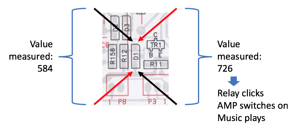
I set my multi-meter to continuity/diode check and measured twice: once with the black probe on the top of D1 and the red probe on the bottom, and once vice versa. See the measurements in the picture below.

Interestingly, with the red probe on the top and the black on the bottom: the relay clicks, the Amp turns on and music can be heard coming from the speakers.
I found that the D1 is a type 1N 4148 diode. So I probably need to look for this one as a SMD type.
Like to hear what you think Keith. Could this be the cause and is it just a matter of replacing it? Or could there still be another underlying cause?
Location: The Netherlands
Favourite Product: BeoSound 9000
My B&O Icons:
1 April 2023 at 15:14 #45042Interestingly, with the red probe on the top and the black on the bottom: the relay clicks, the Amp turns on and music can be heard coming from the speakers. I found that the D1 is a type 1N 4148 diode. So I probably need to look for this one as a SMD type. Like to hear what you think Keith. Could this be the cause and is it just a matter of replacing it? Or could there still be another underlying cause?
The fact that the impedance of your meter was able to trigger the relay tends to mean that a component has gone out of tolerance rather than being totally faulty.
Clarification Points
In your last post you said “I currently do not have equipment to connect via MasterLink” I am assuming you intended to say “Powerlink” rather than “Masterlink“?
Also you said “Plug 3, pin 1 <> pin 2 = 24 volts” which is excellent because that should have triggered the relay. Was the RED light on when you checked this?
Next Steps
As you are using the phono input and taking into account the information in your previous post it is most likely that the fault is in the “Auto Start” section or the D1 diode is not within tolerance or the relay itself.
If you are able to replace the D1 diode with a suitable replacement I think it would be the next step. The negative end (plug 3 pin 1) of the D1 diode is directly driven from the “Auto Start” circuit which takes your source input on the RCA socket. You could therefore also test between plug 3 pin 1 and plug 1 pin 2
Location: Hampshire, England
2 April 2023 at 12:39 #45043The fact that the impedance of your meter was able to trigger the relay tends to mean that a component has gone out of tolerance rather than being totally faulty. Clarification Points
In your last post you said “I currently do not have equipment to connect via MasterLink” I am assuming you intended to say “Powerlink” rather than “Masterlink“?
Also you said “Plug 3, pin 1 <> pin 2 = 24 volts” which is excellent because that should have triggered the relay. Was the RED light on when you checked this?- Ad. MasterLink > Yes, you are right. I meant of course PowerLink.
- Ad. Red light > Yes, the Red LED light was on at that moment.
Concerning the D1 diode Keith, can I just order a ‘1N 4148 diode SMD type’ ?
Location: The Netherlands
Favourite Product: BeoSound 9000
My B&O Icons:
2 April 2023 at 14:50 #45044Concerning the D1 diode Keith, can I just order a ‘1N 4148 diode SMD type’ ?
Yes, you could assuming you have the facilities to change SMD type components. You could also use a standard size diode if you have the same type or a similar one and remove one end of R1 or D1 if that is possible.
First of all, after my last checks I put the PSU/AMP-block back into the speaker casing, and connected everything back to original.
Surprisingly, the red LED went ON again! So that’s good.I looked back at what you said in your previous post and I asked myself given what happened and subsequently using the meter trigger the relay did you also have a ground return issue?
Just a thought and observation..
Location: Hampshire, England
4 April 2023 at 10:30 #45045Leave the D1 as it is. They rarely fail and it seems that you’re able to trigger the system with your multimeter, So Tr1 works.
It’s not clear what your figures are. I guess that these 584 and 726 are mV’s? As your using the multimeter in the diode testing mode. I provides you the forward voltage from a diode. The first number 584 will probably 0.584V and the forward voltage of D1. The second 726 is probably 0.726V and the forward voltage of the internal diode of Tr1 (base-emitter). This is the result of in-circuit measuring of components. This explains why the BL8000 switches on when you put the probes over D1. The multimeter uses a small voltage (mostly around 2V) to test the forward voltage of a diode.
I would start by measuring whether there is a voltage on the base of Tr1 when powering on and off. It should be 0V (in standby) or 0.7V (forward voltage) on the base of Tr1. Resulting in the collector of Tr1 going down to ground level.
D1 is only used to protect Tr1 for negative voltages provided on pin4 on the powerlink plug.Location: Utrecht
4 April 2023 at 10:38 #45046Thnx Beobuddy.
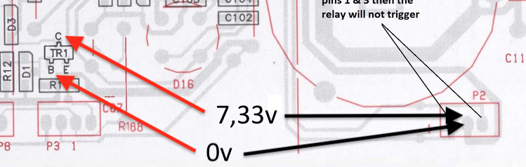
FYI, the multimeter I am using is a Voltcraft VC130-1.So I measured between TR1 and GND/pin 2 on P2, while having power on the BeoLab 8000. So it’s in standby mode, red LED on. Here’s the results:
- TR1 Base <> Pin 2, P2 = 0 volts
- TR1 Collector <> Pin 2, P2 = 7,33 volts

What do you think BeoBuddy, what could be the underlying cause?
Location: The Netherlands
Favourite Product: BeoSound 9000
My B&O Icons:
10 April 2023 at 17:40 #45047@Keith
What do you think after my last measurements?
Suggestions welcome.
Location: The Netherlands
Favourite Product: BeoSound 9000
My B&O Icons:
13 April 2023 at 11:20 #45048Update
The problem with the BeoLab 8000, not switching from stand-by to On (red to green LED), still persists.
PowerLink test
Since I temporarily have a BeoSound 9000 at hand, I decided to test the BeoLab 8000 on its PowerLink connection.Result
When connected via PowerLink, this BeoLab 8000 switches smoothly from stand-by to On. So this works in normal operation.Question
I assume, there is something wrong with the auto-start and RCA combination.
Please advise, what I can do next?Location: The Netherlands
Favourite Product: BeoSound 9000
My B&O Icons:
13 April 2023 at 22:06 #45049Question I assume, there is something wrong with the auto-start and RCA combination. Please advise, what I can do next?
I agree as I previously said…
I cannot help you at present because I am travelling and therefore without circuit diagrams etc.. I will be back from New York late next week..
Location: Hampshire, England
14 April 2023 at 09:54 #45050Thanks Keith, have a safe trip!
Reading back, I noticed you mentioned this:
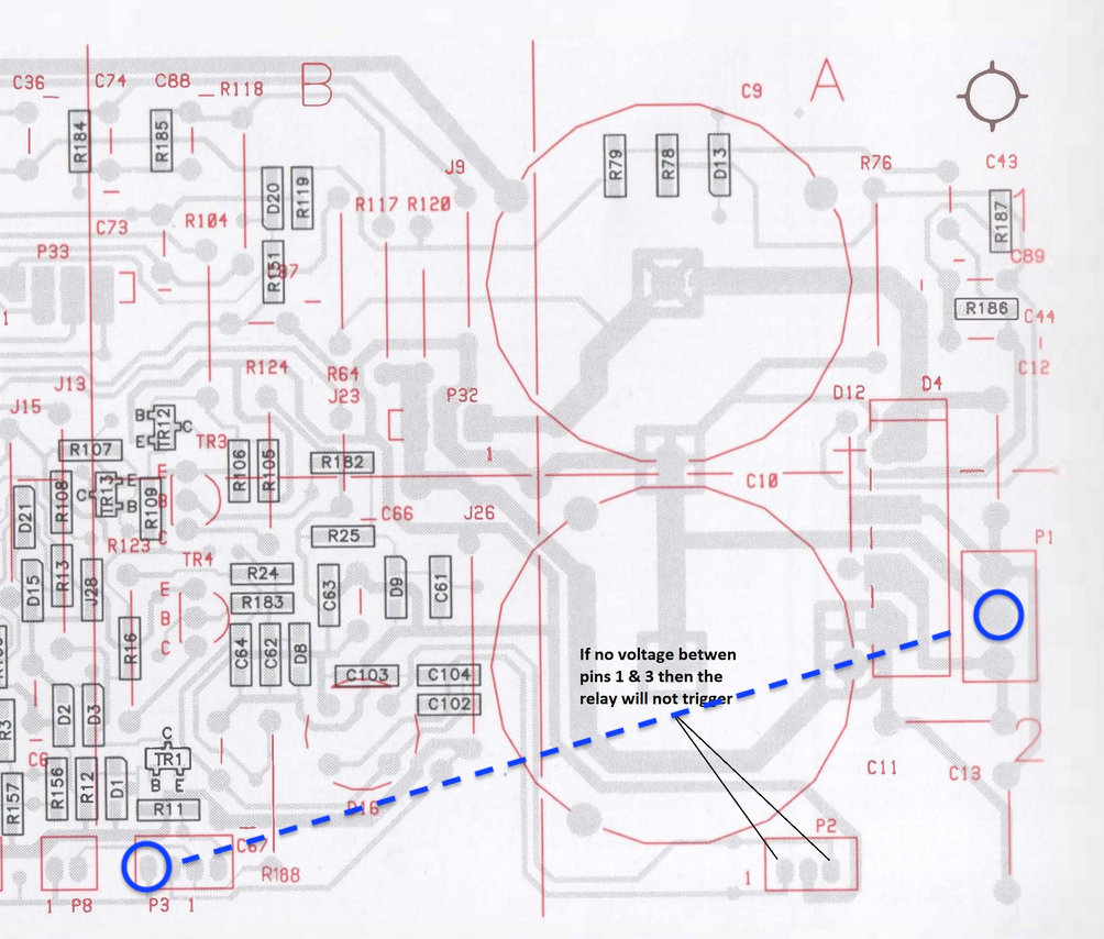
The negative end (plug 3 pin 1) of the D1 diode is directly driven from the “Auto Start” circuit which takes your source input on the RCA socket. You could therefore also test between plug 3 pin 1 and plug 1 pin 2.
And I did not measure that yet. So here’s about that:
- I measured between the two pins as marked in the picture below.
- The measured value is 52 volts.
Hope you have a recommendation for a next step.

Location: The Netherlands
Favourite Product: BeoSound 9000
My B&O Icons:
21 April 2023 at 15:56 #45051I have gone back again and reviewed everything that has been done to date.
A couple of questions came up:-
- When you use the multi-meter which triggered the relay and you heard music, did the LED go green?
- In the last post where you measured 52 volts was that with signal connected to the RCA socket?
It is clear that the problem is in the auto-start circuit and nothing to do with the relay circuit area.
Going back to where you were testing at D1 you said:-
- Interestingly, with the red probe on the top and the black on the bottom: the relay clicks, the Amp turns on and music can be heard coming from the speakers.
Can you please go back and see if you can reproduce this situation.

Location: Hampshire, England
22 April 2023 at 09:57 #45052Thnx Keith!
Here’s a response to all things you mentioned.
(1)
When you use the multi-meter which triggered the relay and you heard music, did the LED go green?Yes, the LED goes green, and the speaker plays music.
(2)
In the last post where you measured 52 volts was that with signal connected to the RCA socket?Yes, it measures 52 volts when a (playing) audio signal is connected to the RCA socket.
Though, it also measures 52 volts when nothing is connected to the RCA socket.Curious to hear what you think of this.
Location: The Netherlands
Favourite Product: BeoSound 9000
My B&O Icons:
23 April 2023 at 10:05 #45053Ernst,
Thank you for your feedback and I have to say it is a difficult problem to understanding based on the information we have to date.
Having said that the basic circuit operates otherwise the system would not trigger with the impedance of your multimeter. This leads me to think that we have a high resistance or open ground connection within the auto start circuit.
At the start of this thread you did mention that the unit was dead with no red light and after you put everything back together you got the red light meaning there was some connection made which was previously not made.
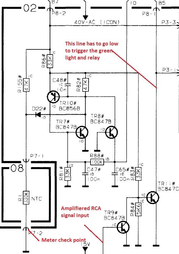
I suggest you check all the ground connections that use plug and socket connections particular associated with the auto start circuit. With the power off and your meter set to resistance connect one meter lead to plug 7 pin 2 as shown below and then check all other ground points have a connection i.e. no resistance.

Location: Hampshire, England
25 April 2023 at 18:51 #45054Thanks Keith!
I am away currently.
When I am back, I will continue making your suggested checks.
Location: The Netherlands
Favourite Product: BeoSound 9000
My B&O Icons:
23 May 2023 at 14:06 #45055Thanks again Keith. Very much appreciated you are still willing to help me!
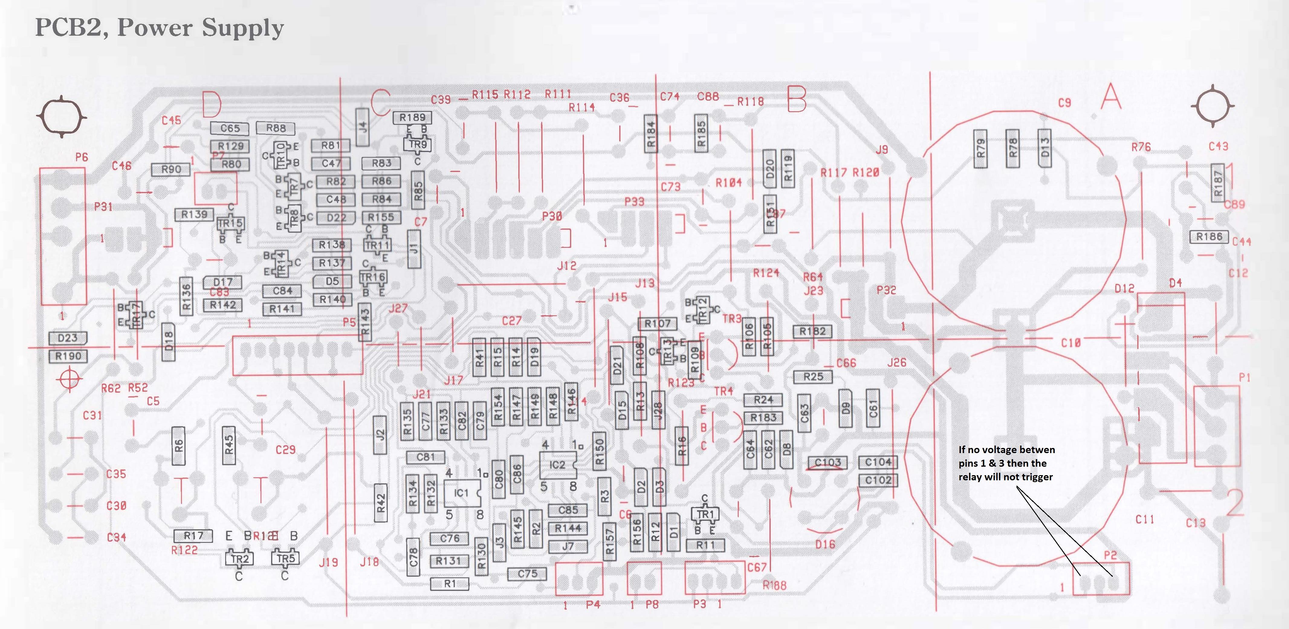
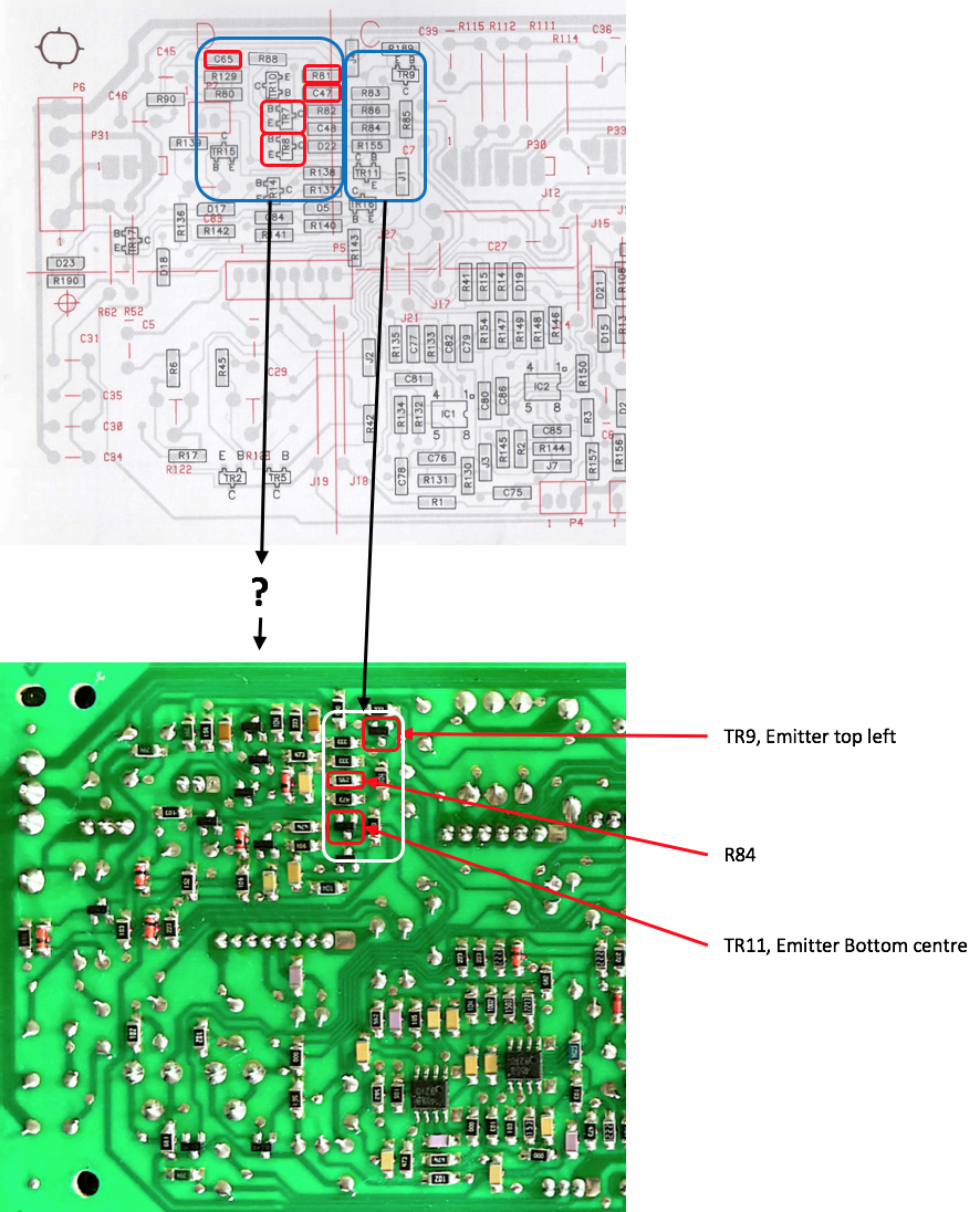
After having returned from abroad after a few weeks, I have immediately started testing what you suggested in your last message. I listed 7 components from your suggestion and picture, to be tested on a GND connection with the multi meter: TR9, R84, TR11, R81, C47, C65, TR7, TR8. I used the visual layout of the board in the service manual (see top part of picture below), to find the exact location of these components.
Here’s the results
First of all I could find TR9, R84 and TR11. Their location according to the visual layout in the Service manual and the PCB itself, was identical. These are the findings on these components:
- P7-2 <> TR9 Emitter = Yes, continuity
- P7-2 <> R84 = Yes, continuity
- P702 <> TR11 Emitter = No continuity on the Emitter, but Yes continuity on the Collector
With the other 4 components I found out that the visual layout from the service manual, and the actual layout of the board differ. So for them I am unsure what their location on the board is.
In the picture below you will see both layouts. In the top image I have marked the 4 components that I can’t match with the layout of the PCB. In the bottom image I have marked the 3 components I could find and which I tested.
Speaker info- Type number = 6801 (B)
- Serial number = 1448 8372
Comments / questionsMaybe the results of the 3 tested components already give you a clue. Is TR11 malfunctioning and the cause?
What do you suggest?

Location: The Netherlands
Favourite Product: BeoSound 9000
My B&O Icons:
4 February 2024 at 18:32 #45056prorsumBRONZE MemberI also got a pair of BL8000 with no signs of life (no light, no relay click). Really hoped for some busted traces because of foam rot, but continuity looks fine. On T2 I measured 230V, but no 44V or 22V. Instead I got 10V and 14V. Can I assume that the standby transformer is gone?
Thank you for your help
-
AuthorPosts


- You must be logged in to reply to this topic.