
Forum Replies Created
-
AuthorPosts
-
 BRONZE Member
Correction, Keith of course!
Location: The Netherlands
Favourite Product: BeoSound 9000
My B&O Icons:

That’s a great improvement Steve!
Thanks.
Location: The Netherlands
Favourite Product: BeoSound 9000
My B&O Icons:
Thnx @Mexking & @ RaMaBo !
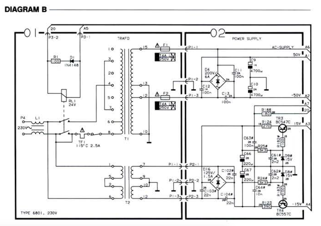
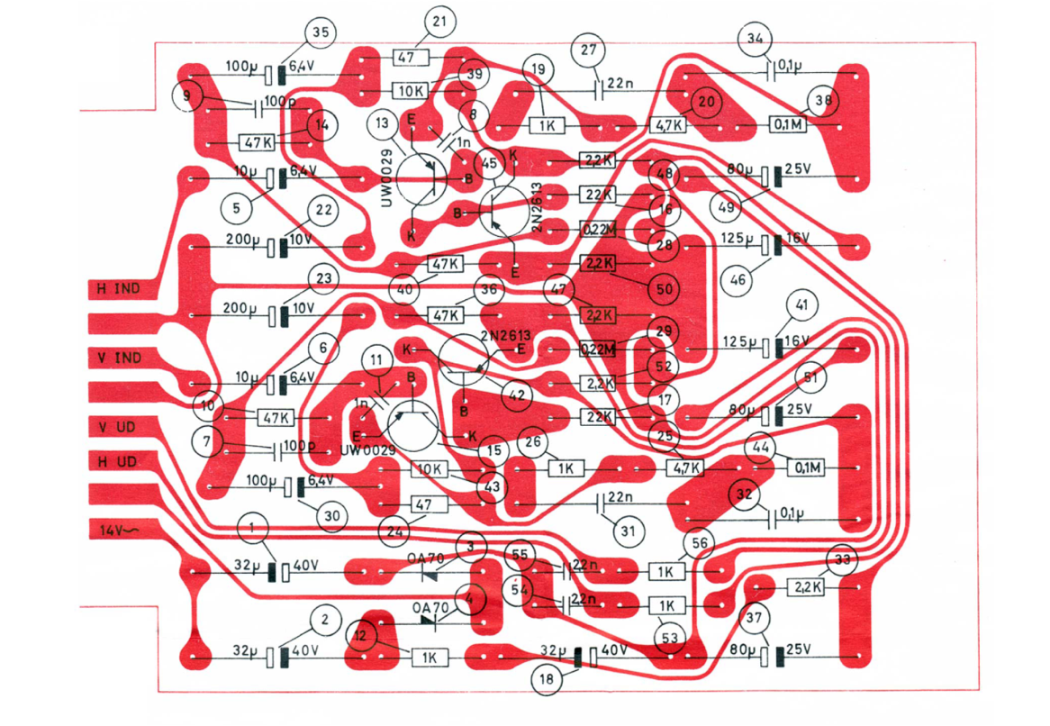
Interesting that there are some differences in the values of certain components; between the info I posted in the start of this Thread and the info in the schematics & parts list of Mexking.
E.g.
- Capacitor #22 and 23 = 200uF/25v vs. 80uF/25v
- Capacitor #49 and 51 = 80uF/25v vs 1.6uF/25v
Is this correct?
Location: The Netherlands
Favourite Product: BeoSound 9000
My B&O Icons:
I am also looking for a permanent DC voltage on the BeoLab 8000. Can you help me confirm that?
Is it 15v DC after capacitor C66?

Location: The Netherlands
Favourite Product: BeoSound 9000
My B&O Icons:
Component search
I have done a quick check for components. There’s two challenges that I see:
- Some components have values that are not very common any more, e.g.: capacitor 10uF/6.4v, 80uF/25v, 100uF/6.4v, etc.
- I have to make sure that the sizes of the components chosen are the same, to make it fit on the original board remake.
Questions(a) Can anyone recommend an online source where components with these ‘vintage’ values can be found?
(b) Are the diode types AO70 & AO81 interchangeable? Or does it depend on the version of the board which one to choose?Location: The Netherlands
Favourite Product: BeoSound 9000
My B&O Icons:
Thnx for hooking in Mexking.
Where do you see ‘OA81’?
In the picture of the board, I can see something is printed in red on the component. But I can’t read it.
The B&O schematics says ‘OA70’. So I assume that is correct.
Location: The Netherlands
Favourite Product: BeoSound 9000
My B&O Icons:
I only have a picture, so I can’t look around the component.
But I believe you are totally right Martin. Your explanation makes perfectly sense!
Thanks again. I am getting closer to have all information for replicating the original!
Location: The Netherlands
Favourite Product: BeoSound 9000
My B&O Icons:
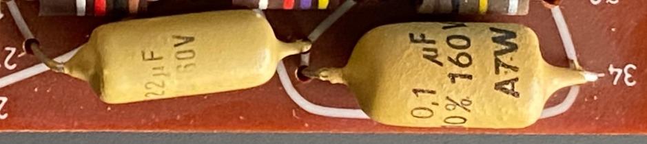
#22 & #34:

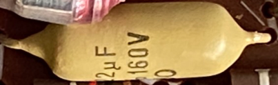
#31:

Location: The Netherlands
Favourite Product: BeoSound 9000
My B&O Icons:
Thnx a lot Martin, clear!
At the bottom right on the PCB, there’s two light brown capacitors: #27 & #34. And on the other side there also two: #31 & #32.
The schematics says:
- #27 = 22n
- #31 = 22n
- #32 = 0,1u
- #34 = 0,1u
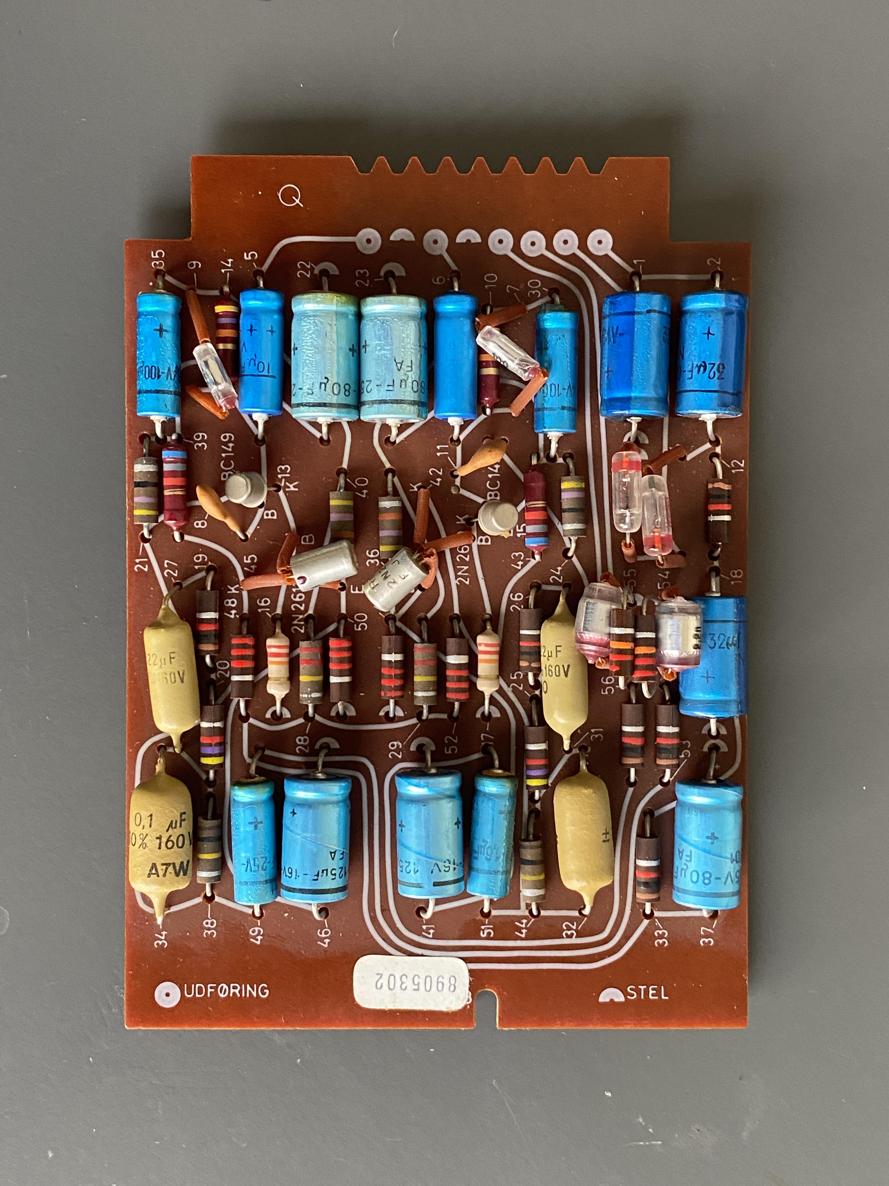
The picture of the components says:
- #27 = 22uF, 160v
- #31 = 22uF, ?v
- #32 = ??, ?v
- #34 = 0,1uF, 160v
Questions:
- I guess the picture is right and the schematics to be ignored on this point?
- Are these ‘Orange Drop’ Capacitors?
- Are they all 160v, and this it matter of the voltage of the replacement differs?
- I guess #32 is also 0,1uF?
Location: The Netherlands
Favourite Product: BeoSound 9000
My B&O Icons:
Now making the full components list, I run into some questions. Obviously, a RIAA pre-amp of the B&O BeoGram 1000 and the SP cartridges are built to be matching with each other. So I want to make sure that I am selecting the right components. And if needed, to select an alternative that works.
So please help me out with this ….
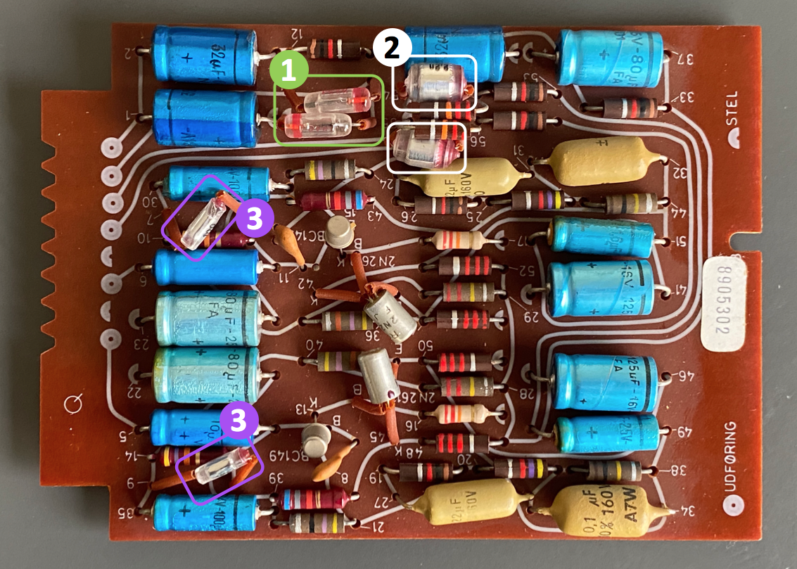
(1) Component 3 & 4 (green box marking in the picture) have type name OA70, and looking at the symbol they seem to be shockley diodes.
Q: Is this indeed a shockley diode? Should I order exactly the same, or is a modern replacement recommended?
(2) Component 54 & 55 (white box marking in the picture) seem to be non-polarised capacitors with value 2,2nF.
Q: What exact type of capacitor is this? Should I order exactly the same, or is a modern replacement recommended?
(3) Component 7 & 9 (purple box marking in the picture) also seem to be non-polarised capacitors but with value 100p.
Q: What exact type of capacitor is this? Should I order exactly the same, or is a modern replacement recommended?
I would be grateful if you add an URL to components you suggest. Thnx!

Att: The PCB picture above, is a horizontal mirror of the schematics below!

Location: The Netherlands
Favourite Product: BeoSound 9000
My B&O Icons:
Thanks for sending the bottom view picture!
Yes, I am aware that my trace image has to be mirrored.Question
The board side that sticks into the slot (so where the 8 tracks in a row are), has 8 notches.
Can you please let me know how deep they are?I think they are a little less deep than the 6mm notch on the other side of the board.
Location: The Netherlands
Favourite Product: BeoSound 9000
My B&O Icons:
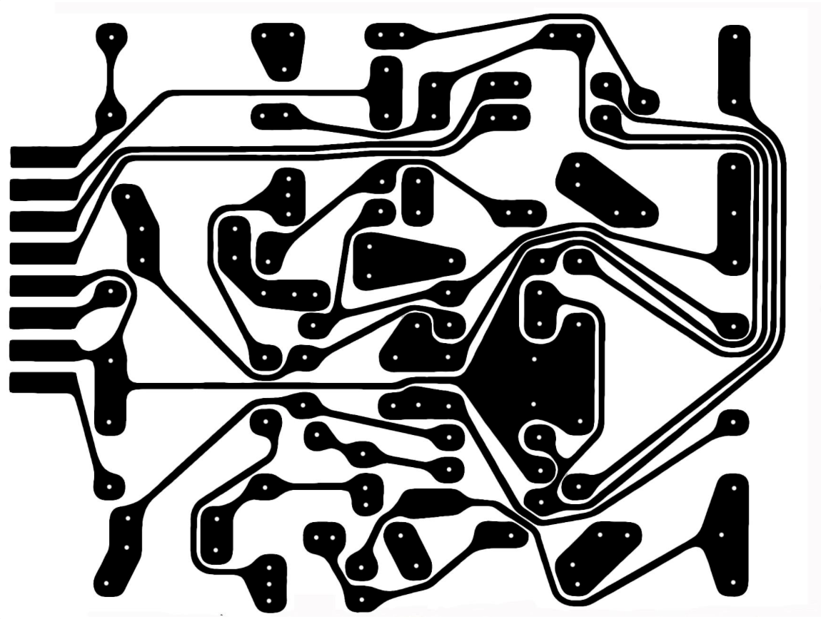
At the moment I am in preparation of making the PCB. My first step is to get the copper traces on a board.
Therefor I have to position and size the image of the copper traces perfectly. I have that picture (see picture below), but it has no outer/PCB border lines, so I have to find out how to size and position this image. (Obviously to get size and proportion equal to the original PCB)
Questions
- Does anyone have such picture of the copper traces pattern, including outside/PCB border lines?
- @Mexking: do you have a picture of the bottom side of the pre-amp board?

Location: The Netherlands
Favourite Product: BeoSound 9000
My B&O Icons:
Update:
I have now collected most information to reproduce the original B&O BeoGram 1000 RIAA pre amp extension board.
- PCB layout (including drawing of the copper traces)
- Components & specifications
- All dimensions in mm of the PCB board
1 & 2 in this post.
3 in this thread:About components, I will continue in the next post in this thread.
Location: The Netherlands
Favourite Product: BeoSound 9000
My B&O Icons:
This is perfect information, thanks so much !!!
I will start to re-produce the original BeoGram RIAA preamp.
Fantastic!
Location: The Netherlands
Favourite Product: BeoSound 9000
My B&O Icons:
That is a way of course. Measuring the slot size, and calculating the other dimensions from there.
Maybe I will post a seperate question for measurements. I guess someone on the forum will have a board, to measure all sizes. If I find those, I will post here what it is.
Thnx
Location: The Netherlands
Favourite Product: BeoSound 9000
My B&O Icons:
Thanks very much for sharing these pictures! That makes it a lot easier to try to make one myself!
Question
Since I do not have a pre-amp board at hand, do you have the outside dimensions of the PCB?Location: The Netherlands
Favourite Product: BeoSound 9000
My B&O Icons:
Thanks all for your responses and contributions!
I have been questioning that myself too. If I look at pictures of the pre-amp board, it seems it is not unthinkable to re-make it. Even in the same look & lay-out as the original. It even makes me wonder if maybe someone did that … (?)

That’s a good suggestion! I will check with Dillen.
Location: The Netherlands
Favourite Product: BeoSound 9000
My B&O Icons:
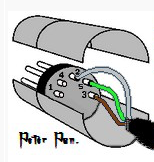
Thanks for referring to Peter Pan’s diagrams Guy, that made it clear!
I like the visual way of understanding the pin layout. In the end, it’s easy to make a mistake if you don’t understand the interpretation of sides: male/female and pin/hole side or solder side.
So a picture like Peter Pan is using, helps a lot:

Location: The Netherlands
Favourite Product: BeoSound 9000
My B&O Icons:
Just to be sure …
When looking at the picture you added about the pin-numbers and what they mean:
- Is the view of this picture, the male connector from the backside (soldering side)?
- Are the ground wires (of the input and output cables that I need to combine to the DIN), combined on PIN 2?
Location: The Netherlands
Favourite Product: BeoSound 9000
My B&O Icons:
I would also be interested, and to know of there’s an English version.
Location: The Netherlands
Favourite Product: BeoSound 9000
My B&O Icons:
-
AuthorPosts