


Home › Forums › Product Discussion & Questions › BeoSystem › BeoCenter 2300: where is the motion sensor for the doors located?
- This topic has 13 replies, 4 voices, and was last updated 3 years, 1 month ago by

-
AuthorPosts
-
18 June 2023 at 04:57 #47225
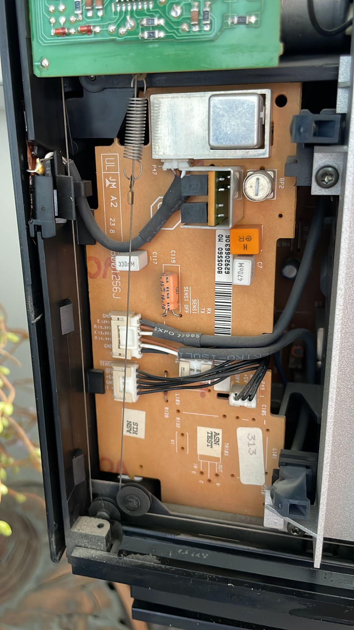
For a BeoCenter 2300 I am looking for the location of the motion sensors which opetaye the glass doors.
I have already detached the glass doors and the black covers (see pictures)

My questions
- Where can I find those sensors?
- Is there one or are there two sensors?
Location: The Netherlands
Favourite Product: BeoSound 9000
My B&O Icons:
 18 June 2023 at 17:25 #47226
 Moderator
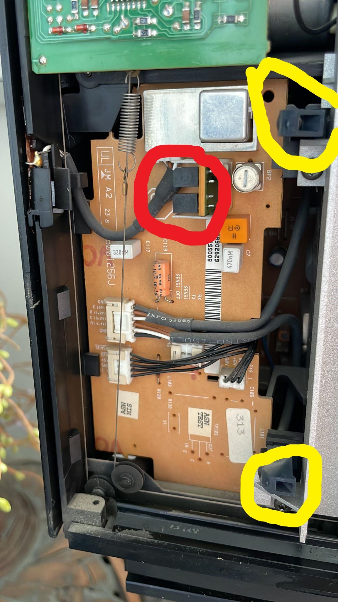
According to the manual, each side has two transmitters and one receiver (the receiver is actually two sensors collocated) EDIT: The receiver is just one sensor each side, see next post)
In my annotation below (of the left hand side), the yellow are the transmitters and the red is the receiver. In your photos I can’t find the receiver on the right (but the transmitters are similar to the left). EDIT See correction in next post.

Location: Warwickshire, UK
My B&O Icons:
18 June 2023 at 17:50 #47227Having stared at the circuit diagram a bit longer I think I was a bit wrong above!!
I think that the red circle is the IR receiver for remote control (the IR transceiver).
I think that the silver square at the top of the board is the door sensor receiver, and you can see a similar silver square on the smaller board on the right hand side.
Location: Warwickshire, UK
My B&O Icons:
19 June 2023 at 08:54 #47228Thanks for sharing Guy!
I am helping a friend, so the BeoCenter 2300 is at a distance for me.
Anyhow, we found out that the sensors are in the black notches you marked with yellow.
They connect via two cables (with each three wires) into one connector. That’s the white connector in your picture with the two grey cables leading to it.What is not clear to me, but I am juyst interested to know …
I believe the sensor in the notches is a LED. So I assume the sensor works with sending and detecting light.
- So does motion detection for the doors work with a kind of light beam, and sensing the interruption by hand motion?
- Does the sensor/LED send the light to the side from underneath the black panel? (So not straight forward, because the black panel covers the notch)
Location: The Netherlands
Favourite Product: BeoSound 9000
My B&O Icons:
19 June 2023 at 10:41 #47229RaMaBoGOLD MemberHi,
the LED in the inwards pointing notch is an IR LED sending invisible light towards the center of the system, but nothing will be reflected to the IR sensor. Except if you move your hand in the IR light area. Then a reflection could be detected 😉 and the doors will be opened.
Location: Near Munich
My B&O Icons:
19 June 2023 at 10:50 #47230Hi RaMaBo, thnx.
- The inwards pointing notch, is that the top one in the picture with the yellow markings?
- Does it mean one notch is sending light, and the other one is detecting reflection (a hand) of lhat light?
Location: The Netherlands
Favourite Product: BeoSound 9000
My B&O Icons:
19 June 2023 at 11:29 #47231RaMaBoGOLD MemberNo, there are two identical IR transceivers on each side, both in the yellow circles.
The IR sensor is in the small hole right of the notch (on the left side sensors)Location: Near Munich
My B&O Icons:
19 June 2023 at 12:09 #47232OK so I have had a more in depth look at this! Looking just at the left hand side, the following is the circuit diagram for the door sensor part of PCB6: (click to expand)

The sensor receiver is OD1, and is remoted from the PCB using connector P47, which is the 3-wire connector just above the red circle in my annotated picture. Follow this wire to find the receiver on the left edge.
The sensor transmitters are OD2 and OD3, which are remoted from the PCB using connector P50, which is the six wire connector that splits into two and supplies the two yellow circled emitters.
The right hand side is similar with connectors P80 (receiver) and P81 (transmitters) respectively.
The plastic cover allows the IR light to pass through for both the door sensors and the remote transceiver.
EDIT: Just for info, this subject was discussed with Leslie on the old forum but sadly the pictures are missing. He experienced problems when painting the black plastic covers, which stopped the IR light from passing through and stopped the doors from working. His thread is here: https://archivedforum2.beoworld.org/forums/p/1118/9340.aspx#9340
EDIT2: You can see the connector numbers and board components very clearly in this Beoparts listing: https://beoparts.com/2020/02/11/beosound-ouverture-ir-receiver-and-door-sensor-pcb-8001753/#jp-carousel-8261
EDIT 3: And this eBay listing still has the IR receiver attached: https://picclick.co.uk/Bang-Olufsen-BO-Beosound-Ouverture-255201529341.html#&gid=1&pid=1
Location: Warwickshire, UK
My B&O Icons:
19 June 2023 at 14:31 #47233Guy has it right. The senders of the infrared light are actual led’s with the shape of a standard 3 mm led. Located in the yellow circles. The receivers have the same shape as the infrared receivers in the red circle, but located at the sides.
This system causes hardly any issues. Most of the time when the doors(and clamper) don’t slide (or moves) there is an issue with its powersupply or other cause.
When you hold the black covers towards incoming sunlight, you can look through them. So painting them isn’t an option indeed.Location: Utrecht
21 June 2023 at 10:23 #47234Thanks Guy & Beobuddy!
So this is what I get from your info:
- There are 4 IR-transmitters, 2 on each side. In the picture they are marked yellow. For the left and right side they are placed symmetrically to each other.
- The IR-receivers look like the notch shape in the red marking, but are in a different location on the side.
Question
- Are there also 4 IR-receivers, 2 on each side?
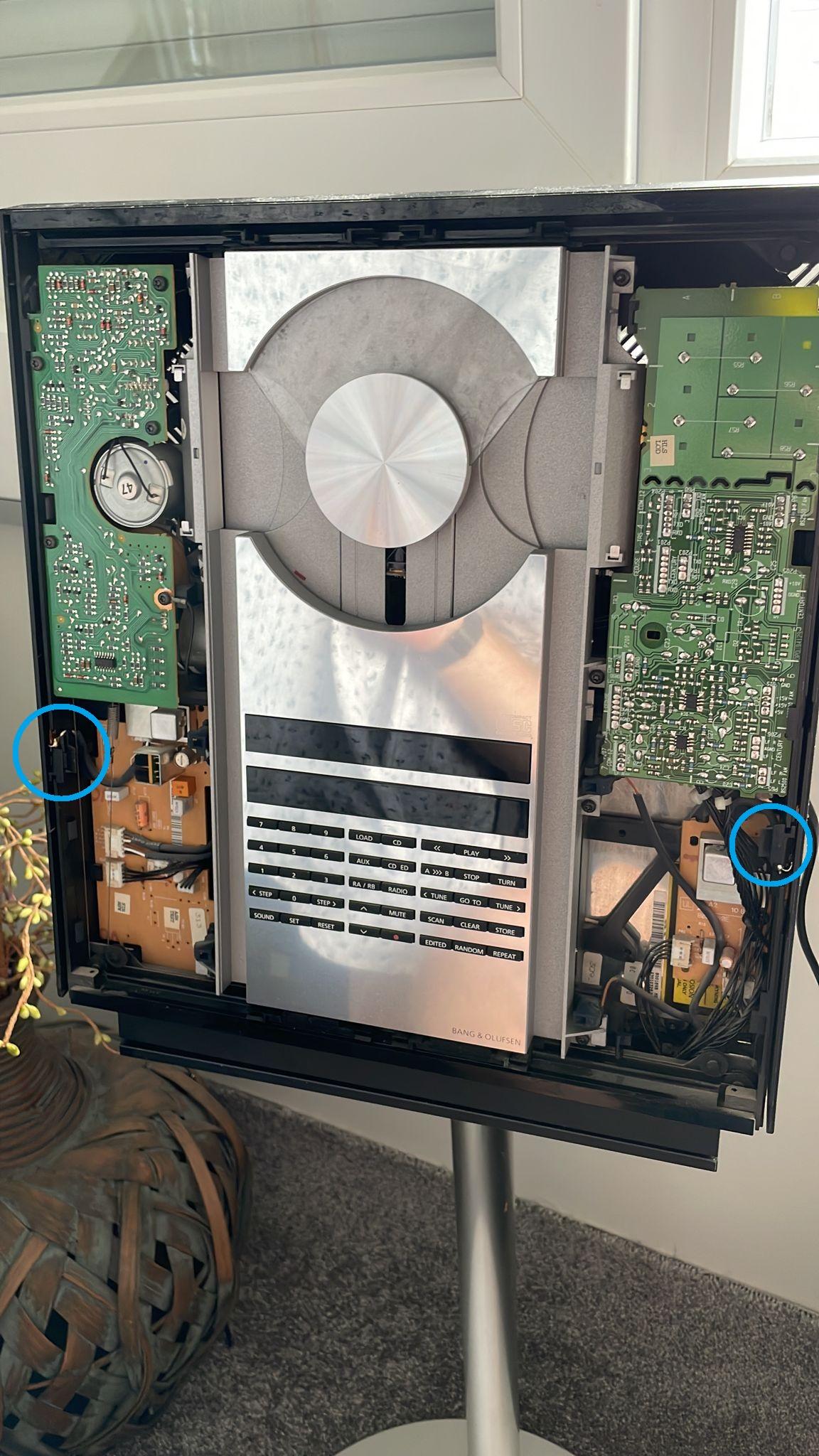
- Are the IR-receivers the ones marked in light blue?
- If so, are the IR-receivers in the right side in the mirrored position to the ones in the left side?
Location: The Netherlands
Favourite Product: BeoSound 9000
My B&O Icons:
21 June 2023 at 10:35 #47235Question Are there also 4 IR-receivers, 2 on each side? Are the IR-receivers the ones marked in light blue? If so, are the IR-receivers in the right side in the mirrored position to the ones in the left side?
There is just one receiver each side (two in total), in the blue circles below:
Location: Warwickshire, UK
My B&O Icons:
22 June 2023 at 07:33 #47236I did not expect these notches to be the receivers.
But this makes everything clear.
Thanks Guy!
Location: The Netherlands
Favourite Product: BeoSound 9000
My B&O Icons:
22 June 2023 at 07:36 #47237Thanks Guy!
No problem – very happy to help and it was useful research for me (and hopefully other Beoworlders!). Next time my BC2300 comes out of storage I will have a much greater understanding of the door control system ?
Location: Warwickshire, UK
My B&O Icons:
22 June 2023 at 07:53 #47238Exactly, I am also happy to understand the working of the motion detection on this B&o system.
Probably helpful to other BeoWorld members.
Location: The Netherlands
Favourite Product: BeoSound 9000
My B&O Icons:
-
AuthorPosts


- You must be logged in to reply to this topic.