Forum Replies Created
-
AuthorPosts
-
 MadskpGOLD Member
I think no audio master ever implemented Powerlink data Rx. I’m still wondering what they had in mind for it.
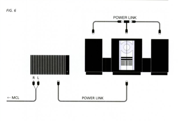
My best guess as also noted in the Beolink Active thread is for use with the ML/MCL converter where powerlink to MCL is also possible as shown in the ML/MCL user manual. For this sceneario commands from the link rooms has to be recieved through the Power Link connection.

However it might not work / being fully implemented on all Powerlink products, and definitely not the Beolink active as I tested in that other thread.
I guess it might have been a kind of a transitional feature when Beocenter/Beosystems/Beosounds began not having built in amplifiers to keep backwards support for the MCL link systems. However as soon as ML became standard in the music systems this feature might have been kind of redundant.
Location: Denmark
MadskpGOLD MemberBS3000 also has no datalink but shows ‘DL’ connections to pins 6 and 7 in the circuit diagram: Specification pages state pins 6 and 7 ‘not used’ EDIT: But for the BS3000 the manual does also say ‘N.C.’ no connection where it joins the microprocessor interface PCB.
Might be something like the BS9000 where the Plug PCB is prepared for the feature, but the functionality not implemented in the end for some reason (cost, time, etc.??)I think there is a mistake in the schematic.That would not be a firstSo probably those pins are a hidden microphone input for recording something on tape.
Yes that feature also seems likely given that the Century could record on tape
Location: Denmark
MadskpGOLD MemberAlso interesting regarding pin 6. If you connect it to ground it will unmute the analoge output on that connector. Haven’t seen that before on other devices.
I could have used that knowledge 23 years ago where I wanted to connect some extra speakers to the Century I had back then 🙂 But interesting that also the user manual says that the AUX on the Century is input only and the specssheet in the servicemanual also says pin 1, 4, 6 and 7 not connected.
I am wondering if it was developed as a way to connect a set of headphones with a special DIN connector as the first generation of the century did not have a headphone jack, but did not end up beeing official in the product.
Location: Denmark
MadskpGOLD MemberJust remembered that the Beosound Century that also does not have datalink.
It has the connections in the DIN connector for PIN 6 and 7 are wired like this:

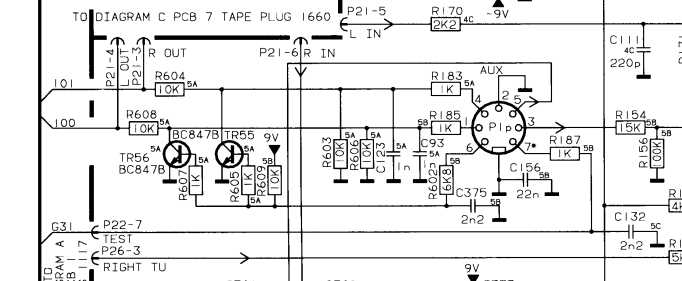
G31 ends at a pin on the MCU called TEST. Could it be that the Beosound 1 had a similar circiut?
Location: Denmark
MadskpGOLD MemberInteresting that they actually routed it to the MCU on BS1. What confuses me a bit is that they are marked with “IN” and “OUT”. Datalink is bi-directional / half-duplex. So there are no separate signals for in/out.
Yes thats a little odd that it is separate IN an OUT. Off course the diagram is only a Block diagram so does not tell the whole story
Could also be that it’s an undocumented service port.
That would make sense in that is undocumented, but on the other hand shouldn’t it be mentioned in the service manual of all places.
I have no BS1 unfortunately but you could hook up an oscilloscope to see if there is being some data transmitted.
I have no oscilloscope at this point, but might end up getting one and see if I can learn something by using it 🙂
Location: Denmark
MadskpGOLD MemberOh yes I can see that now. Thanks for info
Location: Denmark
MadskpGOLD MemberStrange that the data connections are shown in the service manual. Perhaps they are disconnected internally and/or the software was never made compatible. If I get a chance this week I will connect my OneRemote radio to my BS1 aux and do some further tests using my adaptor to switch data between the two pins, plus trying the OneRemote in ‘AAL’ mode as if connected to a BL1611 (I don’t think that I tried that before).
Thanks for joining in. That would be a good test to indicate if something is ticking
Location: Denmark
MadskpGOLD MemberGreat info. Think i has been mentioned now and then, but with reference to the same IR circiut in other products and that it was the blank/shiny caps. So great with actual reference with values.
Location: Denmark
MadskpGOLD MemberMadskp wrote: It does turn on their Beoplay V1, and do control the volume. However the volume function seems to be stuck somehow so it will keep turning up the volume even if I turn of the TV volume functions in the ATV settings. I will have to look into a way to reset the Siri remote to see if this behavior does continue.
That’s strange – but if you can’t reset it and it’s less than a year old them you should be able to raise as a fault with Apple and get a replacement.
I’m at my parent again and have now tried to charge and restart the SIRI remote as described on Apples support pages. Now all functions seems to work, although I don’t have the same posiblities to do long time testing . I have nothing to add to GUY’s observations.
Location: Denmark
MadskpGOLD MemberBS9000 has no datalink on the aux connector. But the powerlink connector has data (DL86?) on pin 6. What do you think ?
I am not sure the data connection i the Powerlink connectors will be of much use depending on the goal.
If it is just to get an extra AUX input without datalink Usecase 6 above https://forum.beoworld.org/wp-content/uploads/2023/12/Beolik-Converter-Usecases-6.pdf can be used.
If it is to be able to control a B&O record player or tape deck it may require to set the BS9000 in opt. 5 or 6 (as a link room) and via Masterlink connect to a Beolink converter 1611 and the via datalink to a Beomaster 3500/4500/5500/6500/7000 or a MCL2AV (in option 0 or with the IR eye covered) where the record player and/or tape deck is connected. It should then be possible to use theses source with a LINK + PHONO/TAPE command from the BS9000
Location: Denmark
MadskpGOLD MemberExcellent work – you must have kept comprehensive notes from all the testing that you have been doing, and it’s great to see it presented so clearly!
Actually my notes was mostly the thread and in my head. Although I had to do some retesting when I began making the drawings as some questions regarding specific option settings and details like that arrised.
In the New Year I will have a more comprehensive look through all the combinations, but I really should prioritise looking for a new house to buy so I can settle down and use some of these setups for real.
Hope you do find a place with lots of extra rooms to enjoy your collection of B&O gear. You may need a seperate room just for your Beolink 1000 and BEO4 collection ?
Many thanks indeed for putting these together for the benefit of all!
No problem. Been meaning to do that for a while now. Also makes it easier to explain these unofficial setups to others
Location: Denmark
MadskpGOLD MemberNext set of use cases attached here
(Moderator Note – new links to use cases added as these had disappeared when forum changed hands)
https://forum.beoworld.org/wp-content/uploads/2023/12/Beolik-Converter-Usecases-1.pdf
https://forum.beoworld.org/wp-content/uploads/2023/12/Beolik-Converter-Usecases-2.pdf
https://forum.beoworld.org/wp-content/uploads/2023/12/Beolik-Converter-Usecases-3.pdf
https://forum.beoworld.org/wp-content/uploads/2023/12/Beolik-Converter-Usecases-4.pdf
https://forum.beoworld.org/wp-content/uploads/2023/12/Beolik-Converter-Usecases-5.pdf
https://forum.beoworld.org/wp-content/uploads/2023/12/Beolik-Converter-Usecases-6.pdf
https://forum.beoworld.org/wp-content/uploads/2023/12/Beolik-Converter-Usecases-7.pdf
https://forum.beoworld.org/wp-content/uploads/2023/12/Beolik-Converter-Usecases-8.pdf
Location: Denmark
MadskpGOLD MemberTo sum up some of the findings in this thread and to make it easier for newcomers and others to understand what it is we have been testing and found out I have compiled a set of examples of use cases for the Beolink converters and the MCL2AV box.
This is not a complete set of examples, and some things can be mixed and matched between the different setups although there are limitations.
I Have tried to describe each use case in words, but also (hopefully) made as much as possible self explanatory with the example drawings.
I am no graphics shark, and do not have any fancy graphics tools, so bear with the limitations in the graphical presentation. Also I would have liked to have more consistency in the icons used, but I have used what I could find.
Any constructive critics, suggestions for changes and/or attention on wrong information is very welcome, and I will try to update the example accordingly.
Because of file size the attached files will be in this and the following post
Location: Denmark
MadskpGOLD MemberA very great use case which has been requested by many ?
Location: Denmark
MadskpGOLD MemberLooks very promising ? Great job and merry christmas to you
Location: Denmark
MadskpGOLD MemberCongratulations to all the winners and merry christmas to everybody
Location: Denmark
MadskpGOLD MemberYes please….
Location: Denmark
MadskpGOLD MemberCan’t wait to get a bonus Christmas present ?
Location: Denmark
MadskpGOLD MemberI hoped this could be solved by setting the correct Sensor and BM options. As mentioned above, maybe it´s part of the actual Datalink command. Unfortunately, I have not found a comprehensive documentation of the actual commands yet.
I don’t think the option settings should make any difference as they only tell the Beomaster if it only recieves audio commands (option 1) or both audio and video commands (option 2).
I actually don´t need the additional MCL Sensor in my day to day use. I´m using it to identify commands from the Datalink protocol. I know about the Datalink manual and I´m already able to send and receive signals
As for the datalink part there are currently 2 members working on projects where they are using datalink if you are not aware of it. They might be helpfull with insights:
B3OHACK3R: https://forum.beoworld.org/forums/topic/masterlink-usb-adapter/
and
PILATOMIC: https://forum.beoworld.org/forums/topic/beotooth-5500-a-datalink-bluetooth-receiver/
Also there is this project on GITHUB:
https://github.com/toresbe/datalink
There was a kit available with an external IR sensor for the BM6500 as mentioned earlier in this thread https://forum.beoworld.org/forums/topic/beolink-passive-ir-eye/page/2/#post-19496 . I might be hard to find one know though.
I was wondering if this is actually an external IR sensor, or if it is providing Datalink commands. But a brief look at the BM7000 schematic suggests that it actually is providing IR commands.
Yeah but it is somehow compatible with other products as mentined by GUY in this post https://forum.beoworld.org/forums/topic/beolink-passive-ir-eye/page/2/#post-19614
Location: Denmark
MadskpGOLD MemberHello. First of this was just some random testing of IR eye’s i different environments, and I might not have thought all scenarios through.Also there are some differences internally in the BM5500 and BM6500 around the data signal in the AUX connection, so it might not work the same as it did with my BM5500 (It is unfortnuatly dead now and given to another person so can’t redo the test of it)With this Setup I´m able to start up the BM6500 via my Beolink 1000 remote. The correct source is also selected. But unfortunately the speakers stay muted and cannot be umuted by neither the “mute” button on the Beolink nor the “mute” button on the MCL Sensor.
Thinking a little more about it in this situation the sensor is connected the same way as if it was in a link room. That means that it will only active the sound for the speaker 2 connections and the speaker 1 and powerlink will stay muted. I didn’t have any speakers connected for my test so didn’t notice that.
However you should still be able to active the powerlink speakers via the BM6500 internal IR eye?
This leads me to asking what you are trying to achieve here? Is it because you wan’t better coverage in a large room, or is the internal IR sensor not working?
There was a kit available with an external IR sensor for the BM6500 as mentioned earlier in this thread https://forum.beoworld.org/forums/topic/beolink-passive-ir-eye/page/2/#post-19496 . I might be hard to find one know though.
Location: Denmark
-
AuthorPosts