
Forum Replies Created
-
AuthorPosts
-
 BRONZE Member
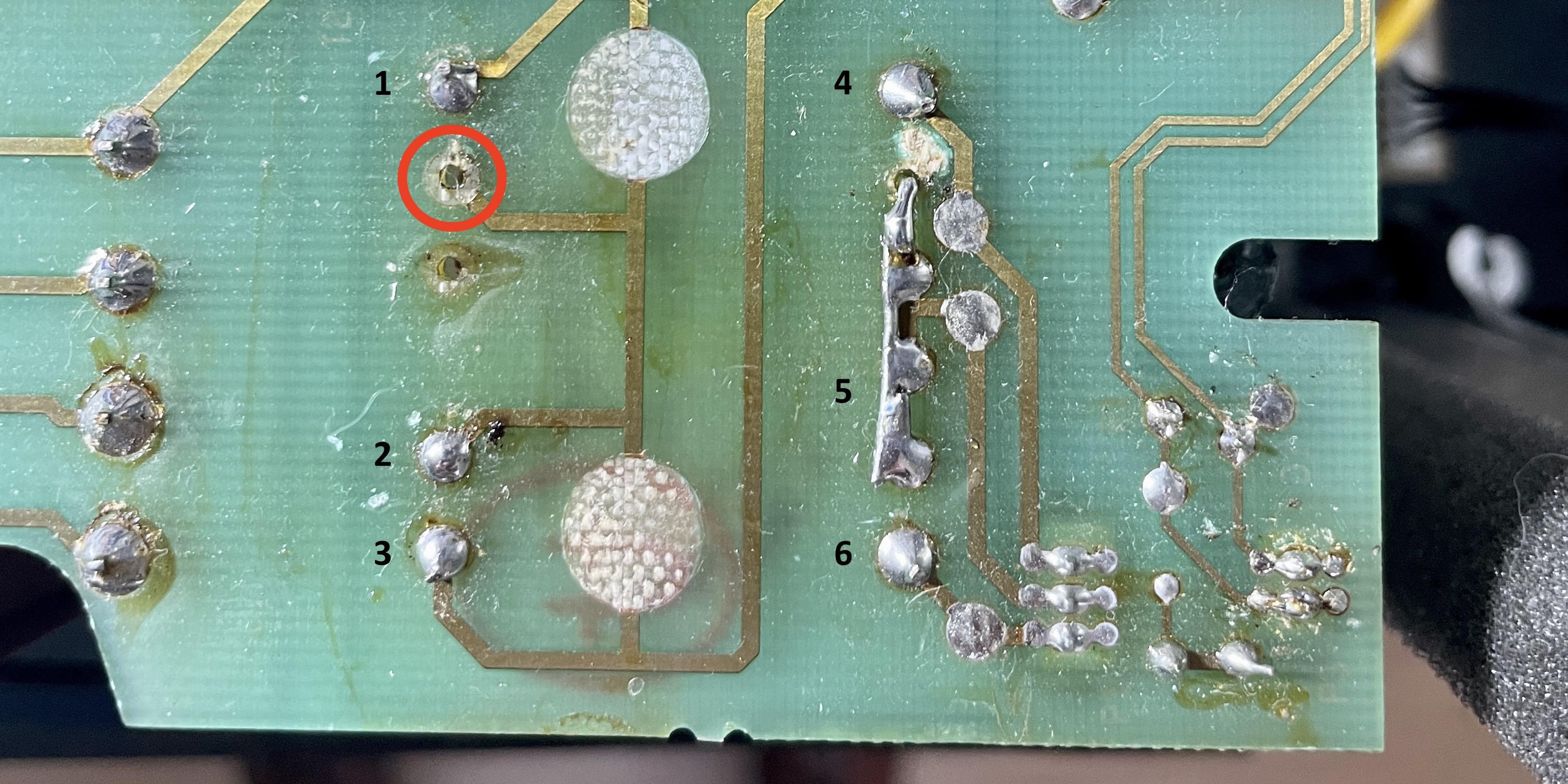
I assume you mean the point in the red circle Martin.
It looks like there should be solder. But there is no pin sticking through that hole, so there is nothing to solder.

Location: The Netherlands
Favourite Product: BeoSound 9000
My B&O Icons:

Thnx Beobuddy for responding!
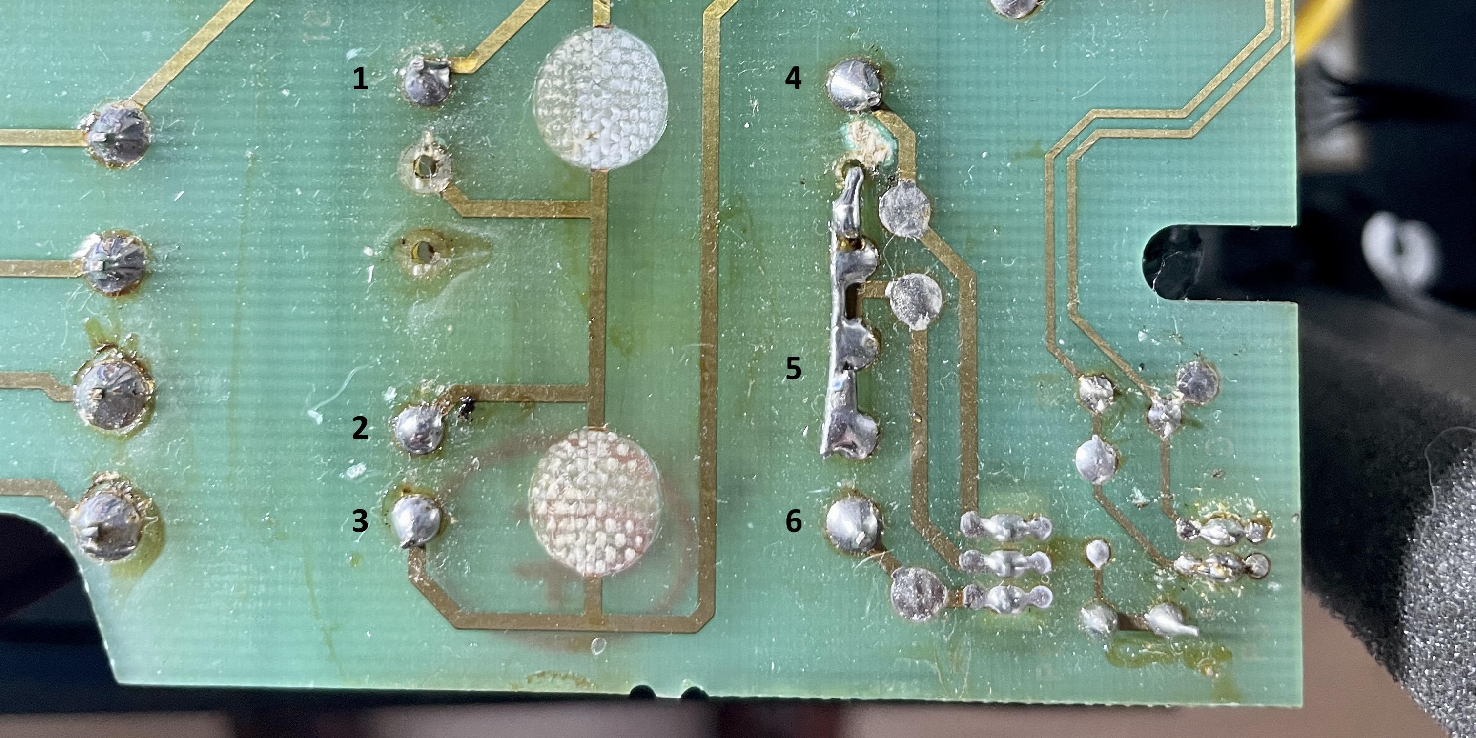
This is what I measured for AC voltage (see also picture).Left side:
- 1 + 2 = 0v
- 2 + 3 = 0v
- 1 + 3 = 0v
Right side:
- 4 + 5 = 0v
- 5 + 6 = 0v
- 4 + 6 = 0v
Just to be complete, I also measured (again) if 230v AC is coming in at the 230v connector on this PCB. The result: positive, 230v has been measured.
Let me know if this is what you meant?
I assume the T2 transformer is dead. I am just wondering why the behavior of the T2 changed from:- Dead (no red LED at all), to
- Alive with errors (LED changing from red to green and back all the time), to
- Now dead again.
Interested in your comments and advise.
Location: The Netherlands
Favourite Product: BeoSound 9000
My B&O Icons:
I might need one.
What is the cost for the T2 trafo and what for shipping to The Netherlands?You can also send that via PM if you prefer.
Location: The Netherlands
Favourite Product: BeoSound 9000
My B&O Icons:
You mentioned that replacements for T2 on eBay are often wrong ones. I found this one on eBay: https://www.ebay.nl/itm/284404189940?hash=item4237cf8af4:g:TZAAAOSwLgpcPjdO
Questions:
- Is this one correct?
- How can I recognize the right one?
Location: The Netherlands
Favourite Product: BeoSound 9000
My B&O Icons:
Thnx Chekler!
Do you also have instruction info for putting new cloth on?
Location: The Netherlands
Favourite Product: BeoSound 9000
My B&O Icons:
Very interesting to see this overview of 4 different versions Martin!
Also interesting that the top left and right and the bottom left, are different but have the same number on the top of the PCB and the same number on the label at the bottom.
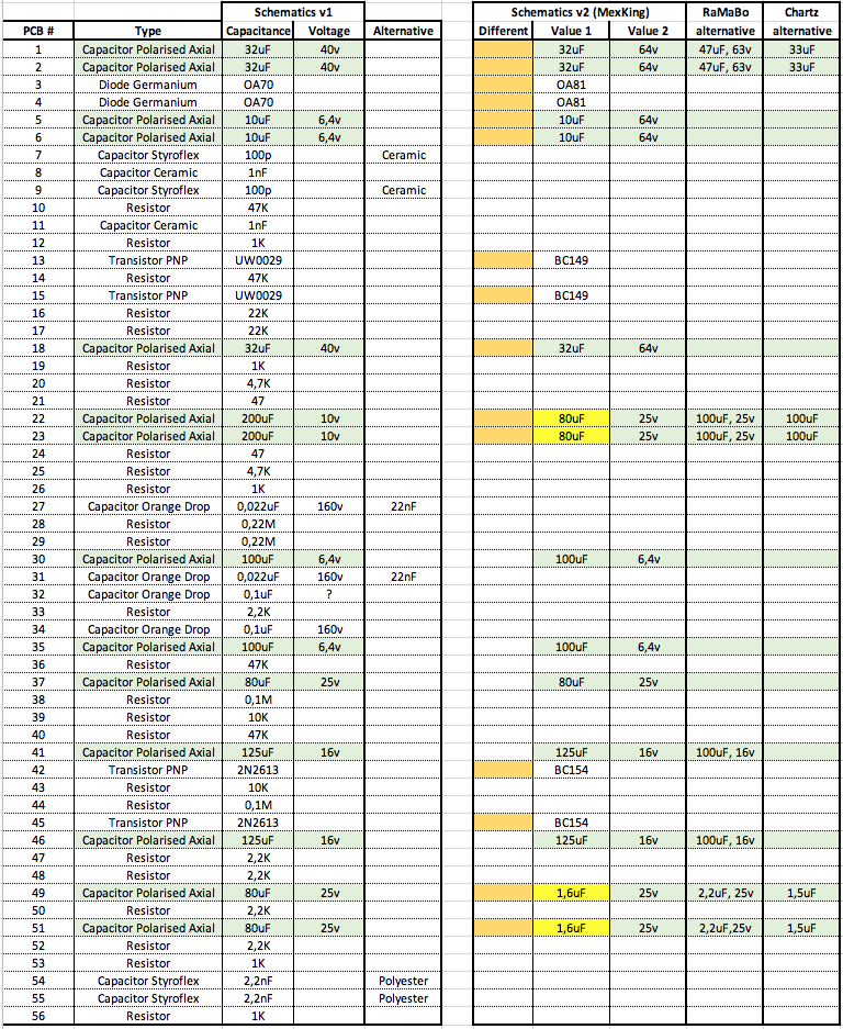
So I have now component list for two versions, see the attached. The right one is based on the info mentioned by Mexking earlier in this thread. And added the alternatives for certain capacitors mentioned by RaMaBo and Chartz.
I think MexKing mentioned the left component list belongs to the PCB trace pattern also shown in this thread.
Question
- Are there really differences in the trace patterns between these two versions?

Location: The Netherlands
Favourite Product: BeoSound 9000
My B&O Icons:
In the process of re-building the original BeoGram 1000 Pre-Amp PCB …
I am now selecting the capacitors for my order. I noticed that it is hard to find the exact same values as the originals. For the voltage it is not such a problem, I can just step up the value for the voltage, and it will still work.
For the capacitance I am not sure. For instance, a capacitor with 32uF is hard to find. Though I do find 33uF. Also 1.6uF cannot be found, but 1.5uF is available.
Also 80uF, I cannot find.
Question
- Will choosing 1.5uF instead of 1.6uF work?
- Same; will choosing 33uF instead of 32uF work?
- Same; will choosing 100uF instead of 80uF work?
- Same; will choosing 150uF work instead of 125uF?
PS. I have searched via:
- https://www.nichiconcapacitors.com/shop/
- https://nl.rs-online.com/web/c/passive-components/capacitors/aluminium-capacitors/
- https://nl.farnell.com/c/passive-components/capacitors/aluminium-electrolytic-capacitors/leaded-aluminium-electrolytic-capacitors
Location: The Netherlands
Favourite Product: BeoSound 9000
My B&O Icons:
Just to be sure, are you looking only for the rubber feet, or also the metal bolts?
Location: The Netherlands
Favourite Product: BeoSound 9000
My B&O Icons:
Felt is an option.
Though I use rubber feet by Delock 10 x 3 mm. These fit in size.
https://www.delock.com/produkt/18309/kaufen.html
Location: The Netherlands
Favourite Product: BeoSound 9000
My B&O Icons:
If you don’t have/know how to handle a multimeter, try to find someone who does, and has understanding of power supplies and amplifiers.
Location: The Netherlands
Favourite Product: BeoSound 9000
My B&O Icons:
Hi mojofml,
Do you have a multimeter and know how to handle that?
Location: The Netherlands
Favourite Product: BeoSound 9000
My B&O Icons:
Very unfortunate to hear that, it is such a beautiful product.
I just ha d a look in the service manual, and noticed that the power transformers are near the PCB’s that are in the middle. Of course that are cooling elements. But I can imagine that high temperatures in such small casing, after years of use, do have impact in the electronics.
What I am saying, is that the soldering of the IR-PCB might suffer from loose connections or cracks in the soldering. If you have nothing to loose, you could try to check that, and do some reflowing of the soldering with an soldering iron, or the ‘oven trick’.
Location: The Netherlands
Favourite Product: BeoSound 9000
My B&O Icons:
Concerning your remote, so it is a BEO4?
Does the display of the BEO4 show responses when you press buttons?
Maybe stupid, but did you check the batteries?Location: The Netherlands
Favourite Product: BeoSound 9000
My B&O Icons:
Hi Jg1976.
You mention you can’t activate your BeoLab 3500 MK1 to listen to the MCL socket.
What does your display show after pressing ‘Menu > Menu > 0 > 4 > Go’ ? (This sequence should switch the BeoLab 3500 to the MCL input)
You could also check your BeoLab 3500 in ‘Test mode’. To do this press ‘Menu > 0 > 2 > Go’
And then check what you see in the display:- ML OK = Master Link Connection is OK
- NO ML = Master Link is not connected
- Error 1 = Address configuration not possible
- Error 2 = Master Link data pulled low
- Error 3 = Master Link data pulled high
- Error 4 = Data collision on Master Link
If you see ‘ML OK’, the BeoLab functions properly, and your cable will probably be wrong. Connections and pins used might be the problem.
If you are handy yourself, you can make such cable yourself. Lots of info on this forum.
You can also ask @Steve of SoundsHeavenly to help you with the right cable.Location: The Netherlands
Favourite Product: BeoSound 9000
My B&O Icons:
Thnx Guy.
Your right, I’d like to build something (small!) that handles auto-sensing and switching from stand-by to ON, automatically.
Location: The Netherlands
Favourite Product: BeoSound 9000
My B&O Icons:
Thanks for your suggestions!
I know both sources sell trigger cables. I prefer to build something myself, as I want to integrate my whole setup inside the BeoLab 2. The smaller I can get things, the better. So I prefer to have a scheme for such and build something myself.
Location: The Netherlands
Favourite Product: BeoSound 9000
My B&O Icons:
I think you guys are right, about the two versions.
I also think the 2nd version is ‘easier’ to rebuild as the values of the capacitors are closer to components available.
Location: The Netherlands
Favourite Product: BeoSound 9000
My B&O Icons:
Very interesting approach!
This is obviously the way B&O equipment handles it.
I would be very much interested in a electronics scheme, and make such to try it out.Any chance you know how such would look like?
Location: The Netherlands
Favourite Product: BeoSound 9000
My B&O Icons:
Thnx very much Guy & Carolpa!
The Playmaker, BeoSound Core or Essence are unfortunately no options for this project. I am looking at a way to integrate the streaming completely inside the speaker casing. So no PowerLink cables, only a power cable and no boxes outside the speaker casing.
So I wonder if the 5v triger is something I can create somehow inside the BeoLab 2.
Location: The Netherlands
Favourite Product: BeoSound 9000
My B&O Icons:
Thanks for responding Die Bogener!
Questions:
- So you mean to say, the only way to get a permanent DC voltage is from the stand-by transformer? Or are there any other points which I could combine with a converter to bring it to DC 5v?
- I think I have a BeoLab 8000 here with a defect standby transformer. Is there any way I can get a replacement stand-by transformer?
Location: The Netherlands
Favourite Product: BeoSound 9000
My B&O Icons:
-
AuthorPosts