


Home › Forums › Product Discussion & Questions › BeoGram › BeoGram 1000: alternative RIAA PreAmp ?
- This topic has 32 replies, 8 voices, and was last updated 3 years, 9 months ago by

-
AuthorPosts
-
2 August 2022 at 02:29 #36549
I have a BeoGram 1000 without PreAmp. I have been looking for the optional PreAmp PCB, but it is hard to find or too expensive.
Therefor I am would like to put in a PreAmp board myself. There is enough space inside to do that.
Questions:
- Does anyone have experience with an alternative PreAmp for the BeoGram 1000?
- Is there any PreAmp PCB product to be recommended?
- Do I have to take into account which SP will be used? (maybe for different output voltages)
Location: The Netherlands
Favourite Product: BeoSound 9000
My B&O Icons:


 3 August 2022 at 16:54 #36550
 ajamesMember
I had one built into a 1200 when I bought it second hand – i worked ok but the volume can be a little low for the SP pickup. There are loads of modules around but I ended up using it with an external amp with variable output. My main concern is that you don’t know how it’s good it’s going to be until you build it. Also you have to build in some sort of power supply, which means adding a transformer and other bits into the cabinet – all of which increase the chances of hum.
I’d also be interested though if someone has built one in and it works well.
Location: United Kingdom
Favourite Product: Beocentre 9300
My B&O Icons:
 3 August 2022 at 18:07 #36551
Aïe, Aïe, Aïe, RIAA’s…
Between the cheap Chineses, the expensive ones, the not so convenient and those who should but don’t and on top of that the dark shadow of the “not that audiophile” ones that may ruin the rendering of your expensive MMC. It’s a real nightmare. When you add the grounding problems and even worse, the need to board it in the cabinet.
That said I don’t understand why nobody recreated the B&O RIAA preamp the was optional with some Beograms: Wasn’t it made of common components?
Location: Paris France
3 August 2022 at 19:10 #36552Thanks all for your responses and contributions!
I have been questioning that myself too. If I look at pictures of the pre-amp board, it seems it is not unthinkable to re-make it. Even in the same look & lay-out as the original. It even makes me wonder if maybe someone did that … (?)

That’s a good suggestion! I will check with Dillen.
Location: The Netherlands
Favourite Product: BeoSound 9000
My B&O Icons:
4 August 2022 at 16:24 #36554
 4 August 2022 at 16:26 #36555
Now you can do it yourself ?
5 August 2022 at 08:40 #36556Thanks very much for sharing these pictures! That makes it a lot easier to try to make one myself!
Question
Since I do not have a pre-amp board at hand, do you have the outside dimensions of the PCB?Location: The Netherlands
Favourite Product: BeoSound 9000
My B&O Icons:
5 August 2022 at 08:56 #36557Hi,
I don’t remember but you can find them by looking where it is supposed to be seated inside the Beogram, right?
5 August 2022 at 09:00 #36558That is a way of course. Measuring the slot size, and calculating the other dimensions from there.
Maybe I will post a seperate question for measurements. I guess someone on the forum will have a board, to measure all sizes. If I find those, I will post here what it is.
Thnx
Location: The Netherlands
Favourite Product: BeoSound 9000
My B&O Icons:
6 August 2022 at 18:40 #36559Update:
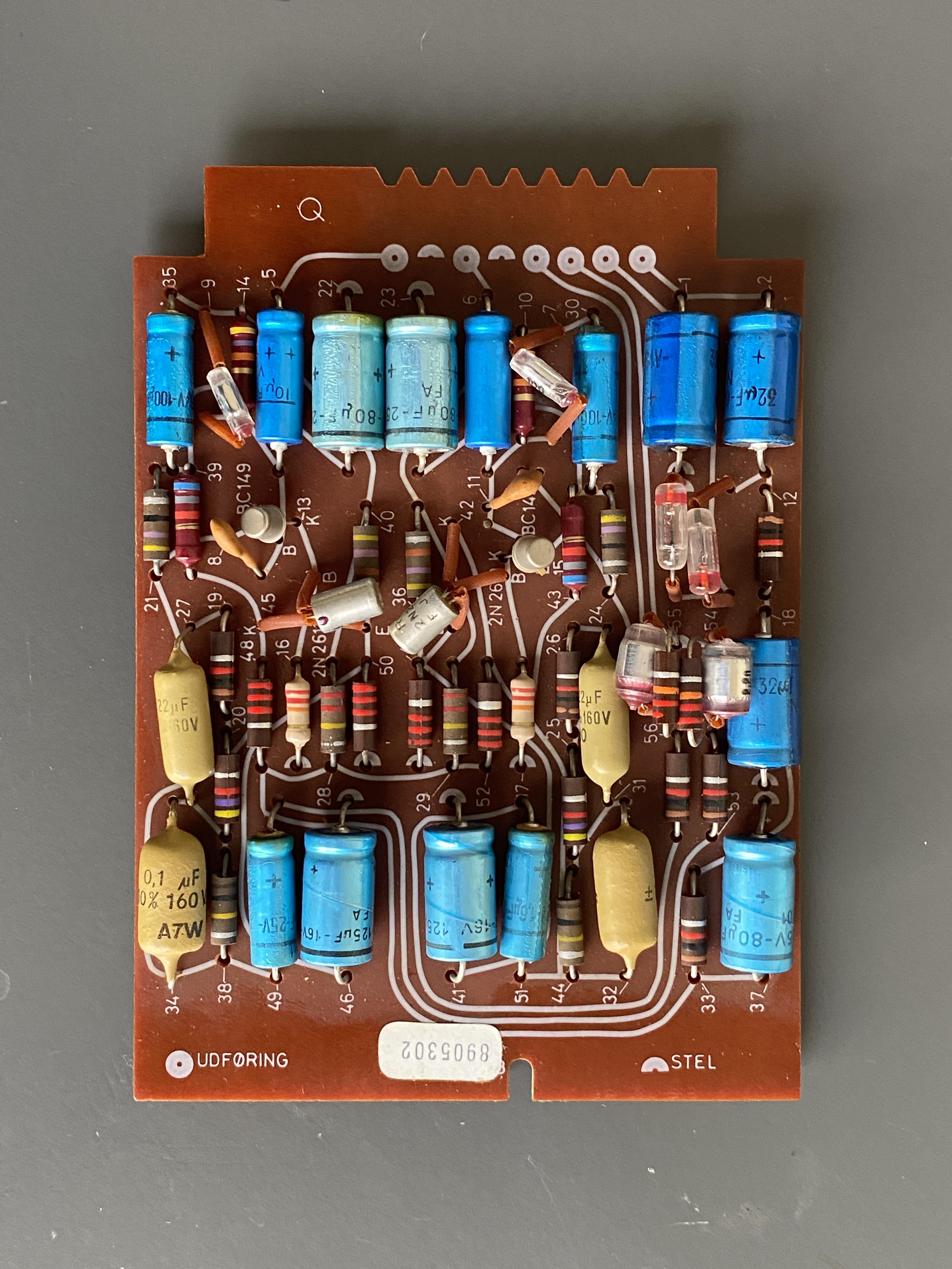
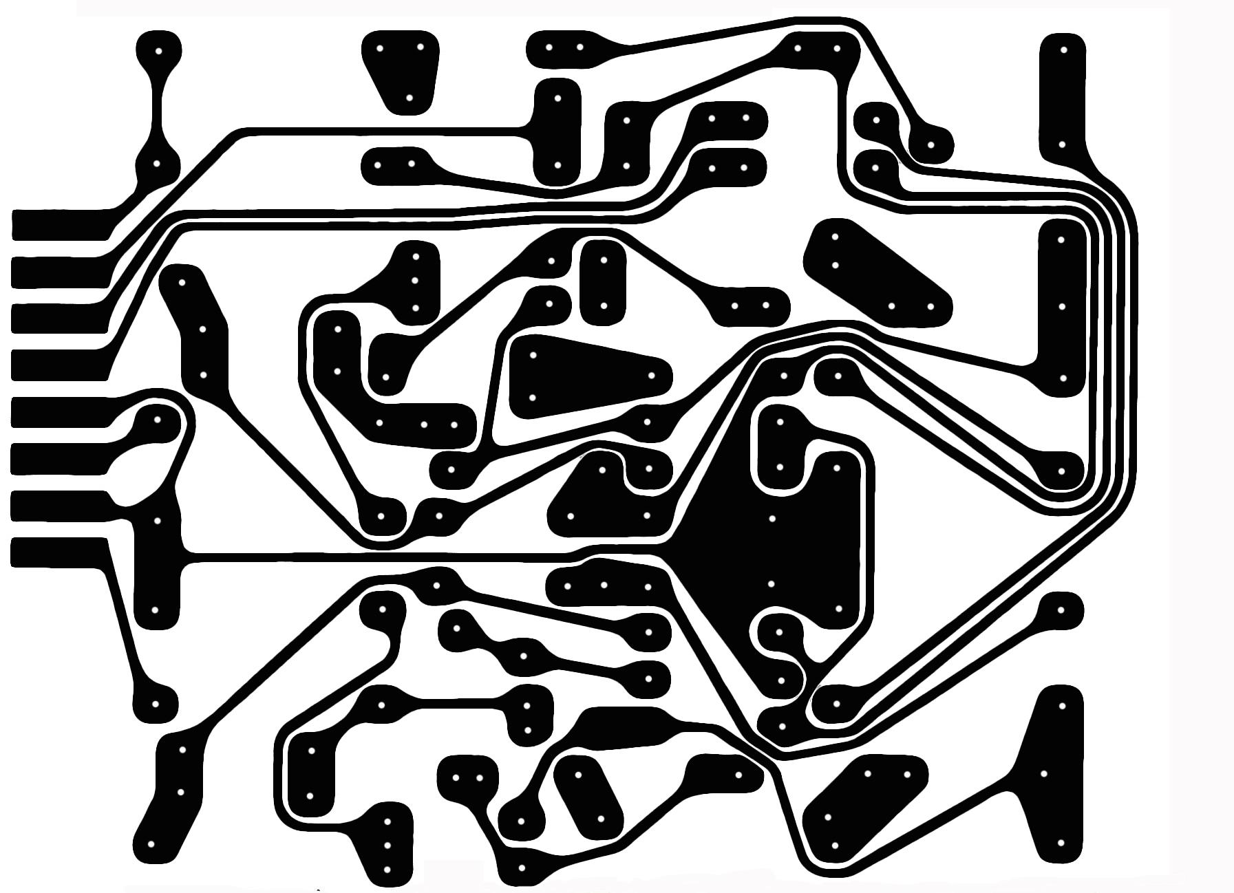
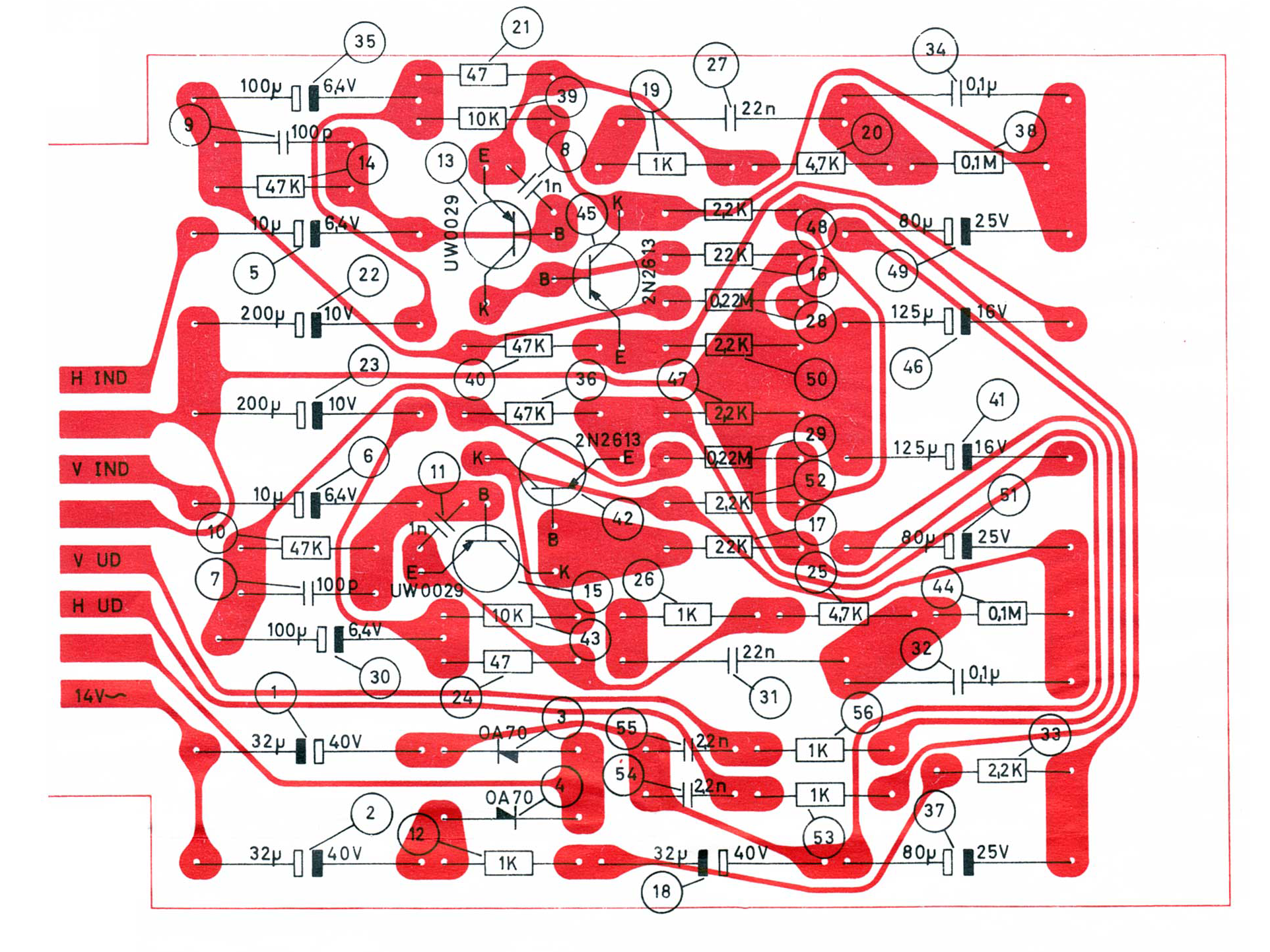
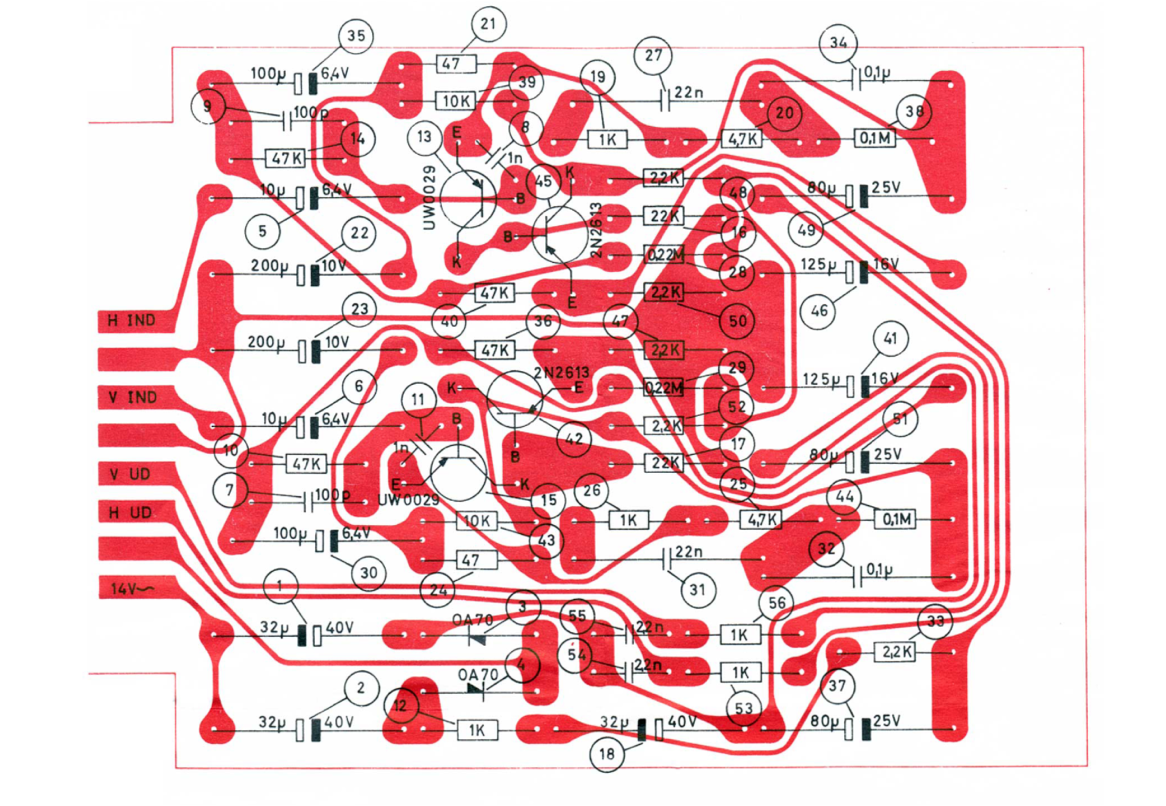
I have now collected most information to reproduce the original B&O BeoGram 1000 RIAA pre amp extension board.
- PCB layout (including drawing of the copper traces)
- Components & specifications
- All dimensions in mm of the PCB board
1 & 2 in this post.
3 in this thread:About components, I will continue in the next post in this thread.
Location: The Netherlands
Favourite Product: BeoSound 9000
My B&O Icons:
18 August 2022 at 10:45 #36560Now making the full components list, I run into some questions. Obviously, a RIAA pre-amp of the B&O BeoGram 1000 and the SP cartridges are built to be matching with each other. So I want to make sure that I am selecting the right components. And if needed, to select an alternative that works.
So please help me out with this ….
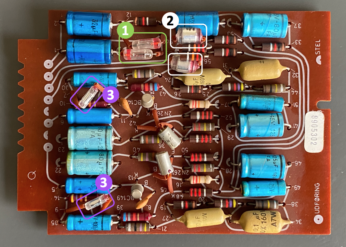
(1) Component 3 & 4 (green box marking in the picture) have type name OA70, and looking at the symbol they seem to be shockley diodes.
Q: Is this indeed a shockley diode? Should I order exactly the same, or is a modern replacement recommended?
(2) Component 54 & 55 (white box marking in the picture) seem to be non-polarised capacitors with value 2,2nF.
Q: What exact type of capacitor is this? Should I order exactly the same, or is a modern replacement recommended?
(3) Component 7 & 9 (purple box marking in the picture) also seem to be non-polarised capacitors but with value 100p.
Q: What exact type of capacitor is this? Should I order exactly the same, or is a modern replacement recommended?
I would be grateful if you add an URL to components you suggest. Thnx!

Att: The PCB picture above, is a horizontal mirror of the schematics below!

Location: The Netherlands
Favourite Product: BeoSound 9000
My B&O Icons:
18 August 2022 at 12:21 #36561DillenModerator1
OA70 are germanium diodes.
Not schottky! (No schottky in power supplies).2 and 3
They are styroflex capacitors.
If you cannot find styroflex, you can fit polyester capacitors for 2 and ceramic for 3.Martin
18 August 2022 at 14:25 #36562Thnx a lot Martin, clear!
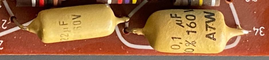
At the bottom right on the PCB, there’s two light brown capacitors: #27 & #34. And on the other side there also two: #31 & #32.
The schematics says:
- #27 = 22n
- #31 = 22n
- #32 = 0,1u
- #34 = 0,1u
The picture of the components says:
- #27 = 22uF, 160v
- #31 = 22uF, ?v
- #32 = ??, ?v
- #34 = 0,1uF, 160v
Questions:
- I guess the picture is right and the schematics to be ignored on this point?
- Are these ‘Orange Drop’ Capacitors?
- Are they all 160v, and this it matter of the voltage of the replacement differs?
- I guess #32 is also 0,1uF?
Location: The Netherlands
Favourite Product: BeoSound 9000
My B&O Icons:
18 August 2022 at 14:27 #36563DillenModeratorSure it doesn’t say 0,022uF?
That would be 22nF.Martin
18 August 2022 at 14:30 #36564#22 & #34:

#31:

Location: The Netherlands
Favourite Product: BeoSound 9000
My B&O Icons:
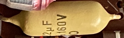
18 August 2022 at 15:57 #36565DillenModeratorThey are not 22uF.
A 1960s 22uF film capacitor would be the size of a beer can.
Look again. Rotate it or lift one end away from the PCB.
I’m sure it says 0,022uF.
That’s quite normal. As is 22000pF, which is also 22nF.
Just like the one next to it says 1uF if you cover the “0,”.Some of the most reliable capacitors on this planet, those “Mullard mustards” are.
Martin
18 August 2022 at 16:00 #36566I only have a picture, so I can’t look around the component.
But I believe you are totally right Martin. Your explanation makes perfectly sense!
Thanks again. I am getting closer to have all information for replicating the original!
Location: The Netherlands
Favourite Product: BeoSound 9000
My B&O Icons:
18 August 2022 at 19:21 #36567Diodes 3 and 4 in the drawing is OA 81 and in your trace pic OA 70. I dont know which one is the correct one
Location: Mexico city
19 August 2022 at 08:51 #36568Thnx for hooking in Mexking.
Where do you see ‘OA81’?
In the picture of the board, I can see something is printed in red on the component. But I can’t read it.
The B&O schematics says ‘OA70’. So I assume that is correct.
Location: The Netherlands
Favourite Product: BeoSound 9000
My B&O Icons:
-
AuthorPosts


- You must be logged in to reply to this topic.