


Home › Forums › Product Discussion & Questions › BeoLab › BeoLab 8000: Power problem analysis, help needed
- This topic has 22 replies, 6 voices, and was last updated 2 years, 7 months ago by
 JBWest.
-
AuthorPosts
-
29 April 2022 at 09:08 #34392
 BRONZE Member
I am working on a power problem with a BeoLab 8000. I tried looking for information on BeoWorld and found this: https://archivedforum.beoworld.org/forums/p/10657/79327.aspx#79327 But I am not sure what to do.
Problem
After having functioned for a while pretty well, this speaker now remains dead. When powered the normal way, via C7 socket in the foot:
- No Red or Green LED
- No clicking of the relay
- No sound form the speakers
Checks
This unit formerly had the old foam, but has been thoroughly cleaned: PCB, components, cables, connectors, sockets.
After that I have checked the PCB’s for damaged traces, especially the ones that often fail after foam rot. But I have continuity on all that are checked. See ‘Tests’ for more about traces on the PSU PCB.
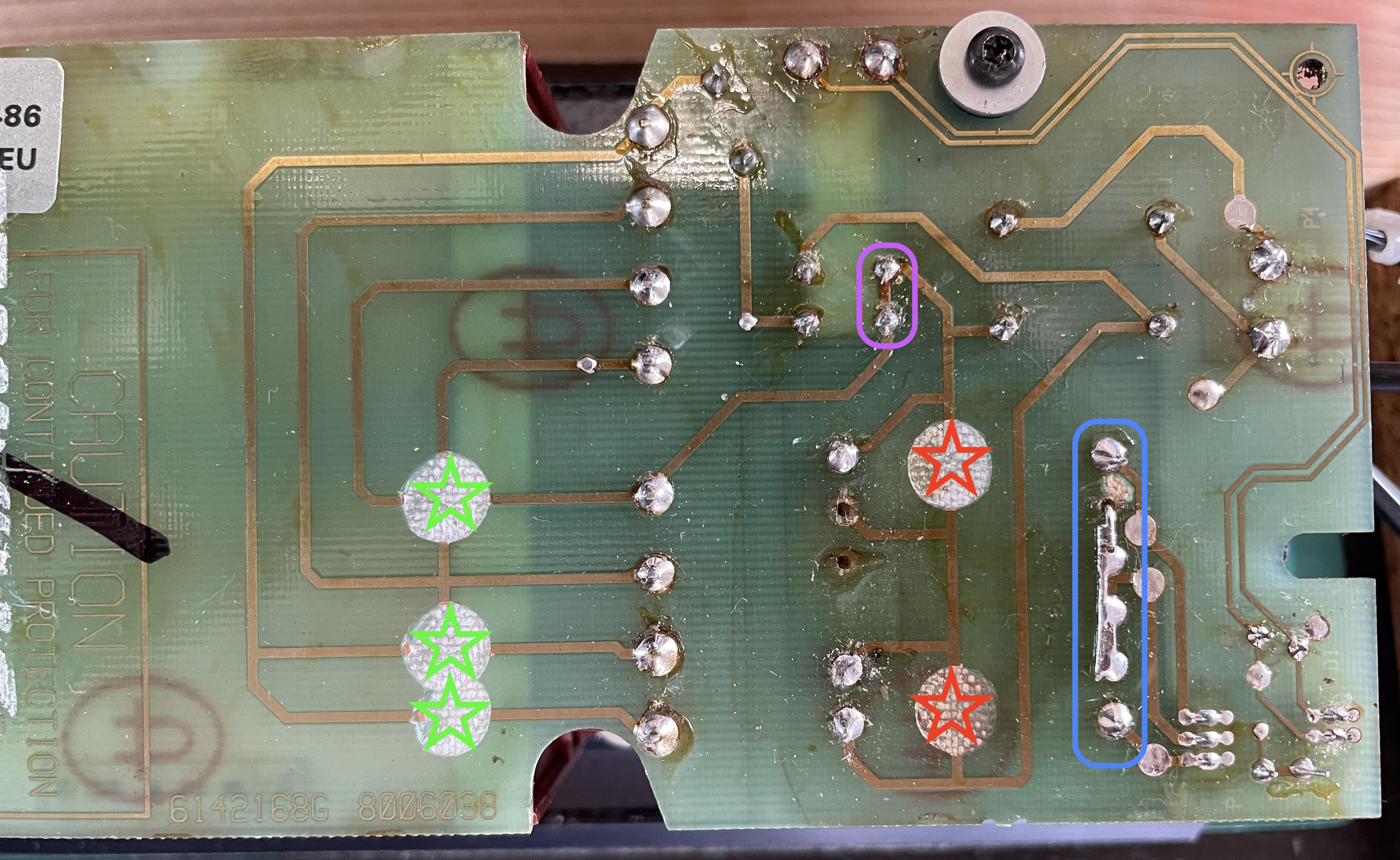
Is is obvious that this unit has had work on before. One example is the manual repair of a trace (see blue box on 2nd picture).
This unit has worked perfectly after the foam cleaning, for about a month.Tests
- When power is directly connected to the pins of P4 (230v input on PCB1) > the relay does click.
- Same as a), but now also the two JST connectors (3 wire and 4 wire) are connected to the connection sockets on PCB 6 in the bottom of the aluminum pipe > the relay does not click, the LED does not turn Red or Green, but stays off.
- Continuity test on the 230v wires from the C7 socket on the outside, to the connector on the inside that plugs into the PSU PCB > this shows positive continuity.
- Continuity test on the relay > I found two pins on the relay that had positive continuity.
The two fuses on PCB1/the transformer side, F1 and F2 > both show positive continuity. - I also measured all traces that have big white dot on them (there are 5 such dots, see 2nd picture). Two of those cover traces without continuity (red star). And three of them have continuity (green star).
- The two fuses on PCB1/the transformer side, F1 and F2 > both show positive continuity.
- LED test. I removed the PCB with the power LED from the bottom of the speaker and tested if the LED still works. Both Red and Green are fine.
Considerations
Since the relay clicks when 230v power goes directly to the PCB (instead of via the C7 in the foot), I wonder if there might be anything wrong on the PCB to which the JST connectors and the power LED are connected. I did a visual check if there might be shorts in the JST connectors, caused by remaining foam rot particles. But couldn’t see such.
Questions
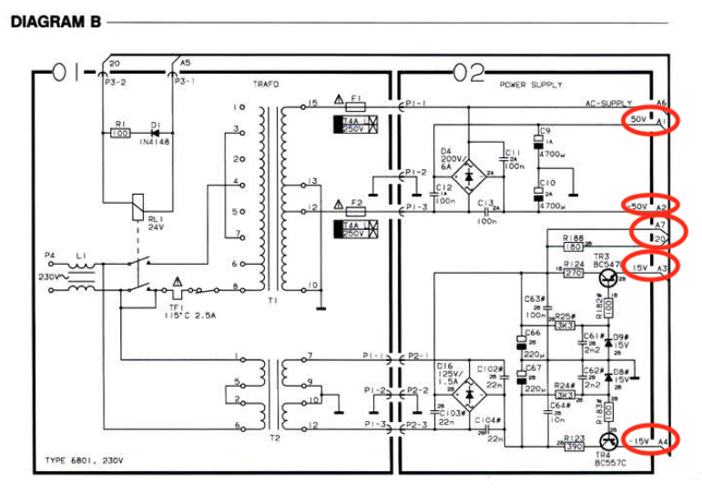
- I think I should measure if the PSU is generating all needed DC voltages. In the scheme I found: point a1 and a2 for + and – 50v, a7 for 20v, a3 and a4 for + and – 15v (see diagram B picture). Though, I have difficulty finding these points on the physical PCB. Where can I find them?
- If I make the measurements, should the JST connectors coming from the foot be connected to PCB02? Or can I do without these connections, and put the whole PSU/AMP block on my desk without these connections?
- Is this the right approach? Or should I focus on different things? Or does someone already know what is wrong? Please mention?
All help is welcome!


Location: The Netherlands
Favourite Product: BeoSound 9000
My B&O Icons:
 30 April 2022 at 14:28 #34393solderon29GOLD Member
It’s quite common for the standby supply transformer(T2)to fail,as it’s permanently connected to power.
Check that you have the two standby supplies +15and -15 at the emitters of TR3 and Tr4.
Check that there is about 23 volt dc at the relay coil.
If none of the above are present,check for about 60 volt AC between P1-1 and P1-2 on pcb 01.
If not present,then the transformer T2 has failed.This is a special part made “in house” by B&O,so you need to ensure that you order the correct one for your country.
You can work on the amp/psu assembly by connecting ac power to P4 on pcb 01,but you should find the looms are just long enough to allow connection from the input sockets,if you prop something under the assembly when it’s out of the casing.
It is possible for the relay RLI to stick open too.As you can see,only one set of contacts are employed.
Nick
24 May 2022 at 19:44 #34394Looking at the picture, it is for sure that the T2/standby/small audio transformer has been replaced. On ebay they sell the wrong version. But I would start by measuring the voltages after T2 and it’s rectifier circuit.
Location: Utrecht
26 May 2022 at 16:21 #34395Thanks for your extensive response and guidance. This is very helpful!
Some clarification questions from my side.- For checking the 23v DC at the relay coil … I believe it has 6 pins. Which ones should I use to measure on?
- You mentioned it possible for the Relay RL1 to stick open. What should I (not) measure when it is stick open? And at which pins should I do the measurement?
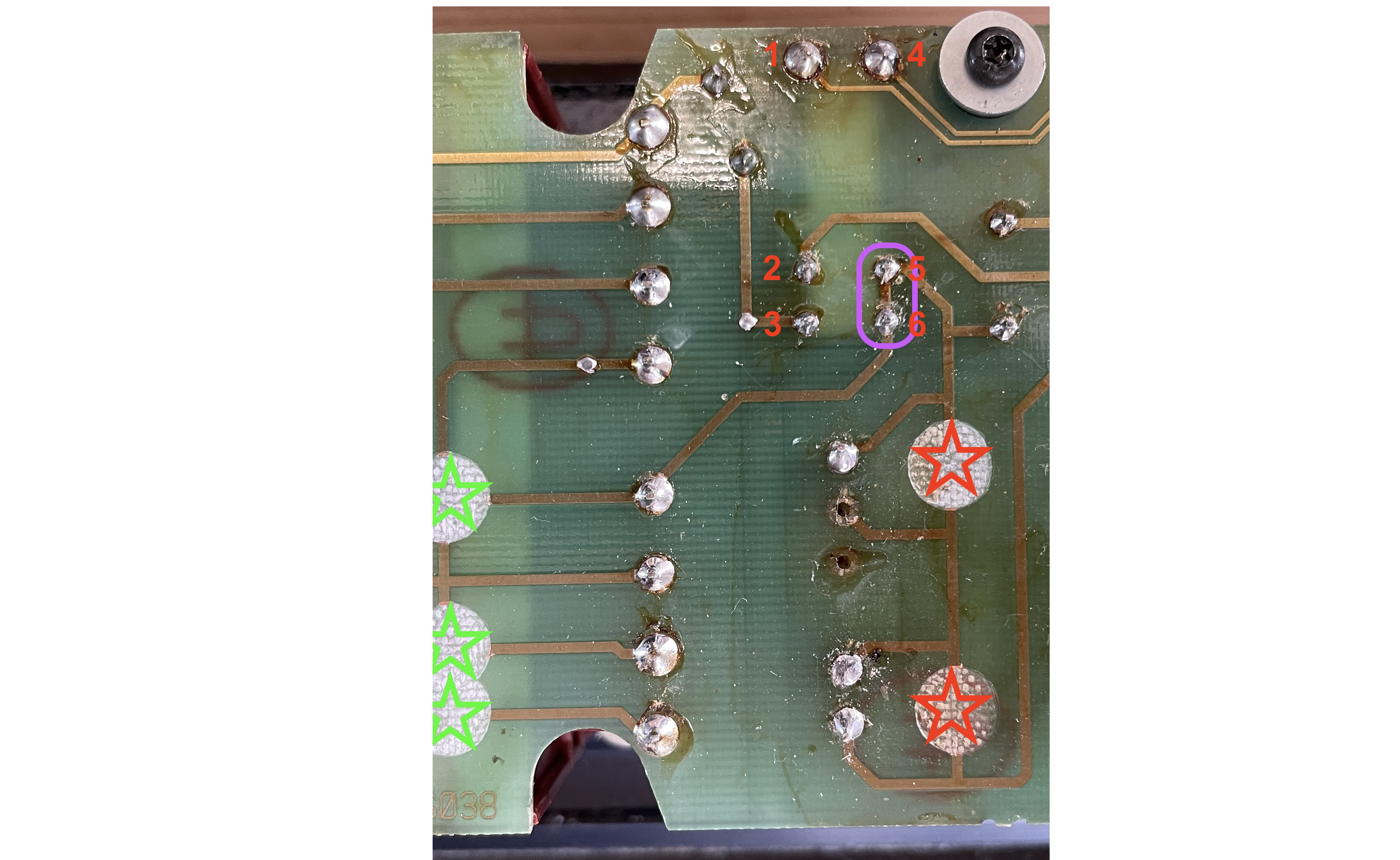
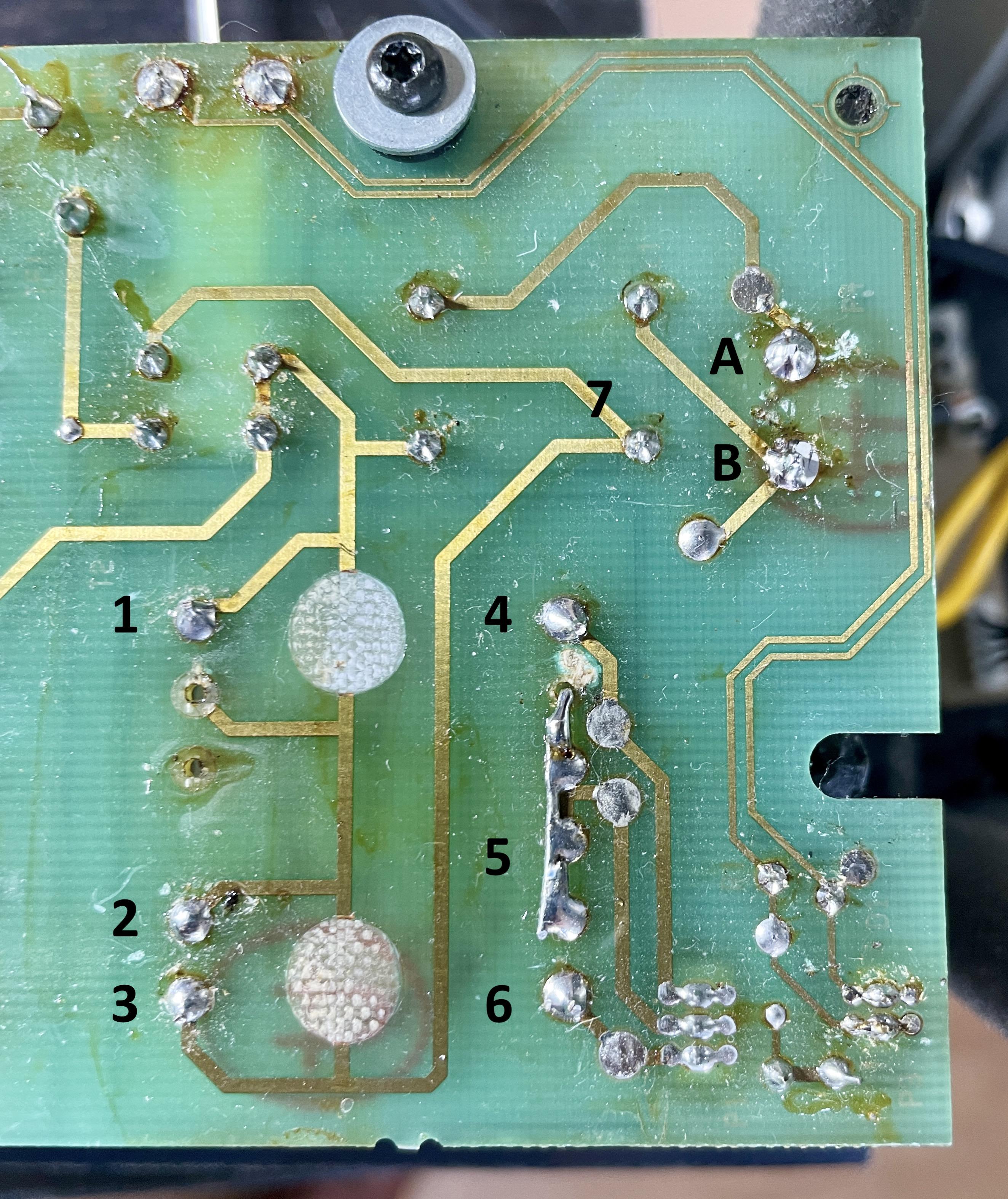
For reference, I added a picture showing the bottom of the PCB and the relay pins with numbers.
Location: The Netherlands
Favourite Product: BeoSound 9000
My B&O Icons:
3 October 2022 at 12:17 #34396You mentioned that replacements for T2 on eBay are often wrong ones. I found this one on eBay: https://www.ebay.nl/itm/284404189940?hash=item4237cf8af4:g:TZAAAOSwLgpcPjdO
Questions:
- Is this one correct?
- How can I recognize the right one?
Location: The Netherlands
Favourite Product: BeoSound 9000
My B&O Icons:
3 October 2022 at 13:15 #34397You can’t see it from the outside. The specifications aren’t mentioned either.
A acquaintance ordered this one some time ago. The needed voltages were way too low.
I have the correct transformer(s) for less..Location: Utrecht
3 October 2022 at 14:19 #34398I might need one.
What is the cost for the T2 trafo and what for shipping to The Netherlands?You can also send that via PM if you prefer.
Location: The Netherlands
Favourite Product: BeoSound 9000
My B&O Icons:
4 October 2022 at 13:03 #34399Did you measure on the outer pins of T2? The 2 outer on the left side should have 230V AC and on the right outerside there should be around 36V AC? The bridge on the right side has been done to connect both windings on the secondary side of T2 for symmetrical use/powersupply.
Location: Utrecht
4 October 2022 at 13:17 #34400Thnx Beobuddy for responding!
This is what I measured for AC voltage (see also picture).Left side:
- 1 + 2 = 0v
- 2 + 3 = 0v
- 1 + 3 = 0v
Right side:
- 4 + 5 = 0v
- 5 + 6 = 0v
- 4 + 6 = 0v
Just to be complete, I also measured (again) if 230v AC is coming in at the 230v connector on this PCB. The result: positive, 230v has been measured.
Let me know if this is what you meant?
I assume the T2 transformer is dead. I am just wondering why the behavior of the T2 changed from:- Dead (no red LED at all), to
- Alive with errors (LED changing from red to green and back all the time), to
- Now dead again.
Interested in your comments and advise.

Location: The Netherlands
Favourite Product: BeoSound 9000
My B&O Icons:
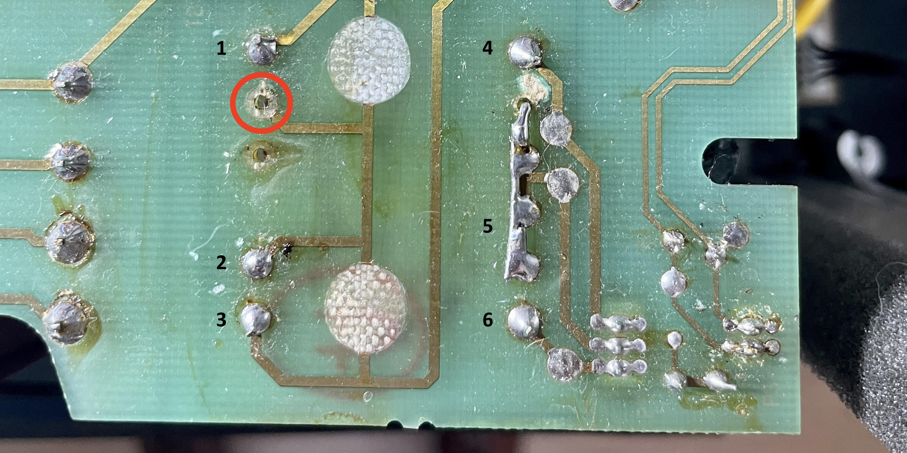
4 October 2022 at 14:35 #34401DillenModeratorMissing solder pad at the transformer pin below number 1 in your photo?
Martin
4 October 2022 at 14:37 #34402Between 1 and 3 you should measure 230V AC. If that’s not there, then there has to be a failure between the (board)connector and the transformer. For T2 there isn’t any voltages to transform.
It (sometimes, rare) happens that the noise filter (Coil) fails. I assume that you thoroughly checked for broken traces.Location: Utrecht
4 October 2022 at 14:41 #34403Missing solder pad at the transformer pin below number 1 in your photo? Martin
The missing pads aren’t the problem. The primary winding sits between pin 1 and 3 on that replacement transformer. The old transformer was capable to be used for several voltages and accordingly connected.
Location: Utrecht
4 October 2022 at 14:43 #34404I assume you mean the point in the red circle Martin.
It looks like there should be solder. But there is no pin sticking through that hole, so there is nothing to solder.
Location: The Netherlands
Favourite Product: BeoSound 9000
My B&O Icons:
4 October 2022 at 14:55 #34405DillenModeratorDo you have continuity (ohmic resistance) from pin 1 to 3 (speaker disconnected from mains)?
Martin
4 October 2022 at 14:56 #34406The pins from the original transformer are bend and then soldered. When removing the old burned transformer it is hard not to damage the pad. Even with appropriate tools.
Location: Utrecht
4 October 2022 at 15:00 #34407So I did some measurements again.
- Between 1 + 3 = 0 volts / and also no continuity.
Also checked for continuity between the incoming 230v connector and Pin 1 and 3 of the T2 transformer.
- Between A + 1 = yes, continuity.
- Between B + 2 = no continuity.
- Between B + 3 = no continuity.
But I also found something interesting:
- Between B + 7 = yes, continuity.
- Between 7 + 3 = no continuity. (Visually I cannot see any broken trace)

Location: The Netherlands
Favourite Product: BeoSound 9000
My B&O Icons:
4 October 2022 at 15:28 #34408So, you measure from 7 along the trace to point 3 where the trace is broken.
But, you should have continuity between A and 1, and between B (through 7) and 3. Piece of wire between 7 and 3 will solve it.(or at the point of where the trace is broken)Location: Utrecht
4 October 2022 at 15:36 #34409Thnx BeoBuddy.
So, you measure from 7 along the trace to point 3 where the trace is broken.
- Yes, confirm. From 7 to 3 there is no continuity.
But, you should have continuity between A and 1, and between B (through 7) and 3.
- Between A + 1 = continuity.
- Between B + 3 = no continuity.
- Between B + 7 = continuity.
Piece of wire between 7 and 3 will solve it.(or at the point of where the trace is broken).
- I am gone do that.
Location: The Netherlands
Favourite Product: BeoSound 9000
My B&O Icons:
4 October 2022 at 15:46 #34410Update, after adding a wire between 7 + 3.
I added the wire and made a first check powering the system. Result:
- I immediately heard the relay clicking.
- The power LED became alive again; turned green and back to red.
Next I measured AC voltage on T2:
- Between 4 + 6 = 43 volts AC
- Between 4 + 5 = 22 volts AC
- Between 5 + 6 = 22 volts AC
Are these the correct measurements?
Location: The Netherlands
Favourite Product: BeoSound 9000
My B&O Icons:
4 October 2022 at 19:57 #34411Die_BogenerBRONZE MemberWithout load… yes.
It’s a 2-coil transformer, for around 2 x 20V 150mA .
-
AuthorPosts


- You must be logged in to reply to this topic.