Forum Replies Created
-
AuthorPosts
-
Hi Alf
If you connect to mains is the “red dot” in the display lit?
Where did you measure the 19.8 Volts? Direct at the Relay?
There is a voltage drop via TR 18 as well so there won’t be 24 volt at the relay.
19.8 V should be enough voltage to engage the relay anyway.
Is the voltage dropping to zero after you heard the relay working?
Had already bad connections from PCB 6 to PCB 7 check also for bad soldering or corroded plugs and/or contact pins
How is the voltage on Collector of IC9 and IC10 ?
Steady about 22 to 24 volt after switching “ON”?
Follow the schematic until you reach the CPU, check the whole way via TR11, TR12, TR18, P48-5, P76-6, R55, PIN16 IC4 for bad solderjoints or breaks.
Same for the POWER ON route via IC9, TR2, TR1, TR4, TR5, P48-4, P76-7, R57, PIN16 IC4
Did you already renew some caps? Here speacialy C35 10 uF on the 5 Volt Regulator right hand on the heatsink, often the reason for some trouble
Regards
Christian
Just send me a PM and we can share the. stl via Email.
Regards
Christian
I wish you really good luck and let us know if you got any progress.
Regards
Christian
Hi ” Matador”
I’d like to ask if you share the .stl file for the clamps.
That would be great ;-))
Kind regards
Christian
Hi
If you have checked and rechecked that the new transistors are the right ones and in the right place I would start here as Beolover does:
https://beolover.blogspot.com/2015/04/beogram-4000-cleaning-of-tone-arm.html
same here:
https://beolover.blogspot.com/2015/05/beogram-4000-restoring-slow-slide-transport.html
There are a lot of very helpful information related to the Beogram 400 on Beolovers site too, have a look.
Kind regards
Christian
Hi
The Strobe issue on the BM 8000 was just a misaligned Pot R15 which has to be adjusted to minimum ~3.6 Volt, the Pot was turned the whole way down and the CPU did not recorgnized the too small signal below 3,6 Volt.
This Pot is not present in the BM 6000.
If you can’t measure any strobe signal there must be something wrong with the CPU, I think, but maybe someone else has a similar experience with the BM 6000 and can help with a good idea or with a used and working CPU for a fist full of $
Had already 2 BM 6000 which I could not bring back to life because CPU related trouble. Doesn’t mean that the CPU’s in my case were really dead, but after working on these for days and not finding the error I made a decision to sell them for spare parts.
It hurts to give these iconic units away but…..
Sorry that I can help you further.
Kind regards
Christian
Hi
Sounds like there is an total recap service needed.
Don’t forget the 47 uF in the uPC Can.
Resoldering of all sockets ( pluigs) is also a good idea.
Kind regards
Christian
Hi Glitch
I’ve had a similar problem with a BM 8000 where the “SSTROBE” Signal wasn’t present.
If there is no STROBE no button and Displaywould work.
It’s only a small straw but maybe you check the Strobe Signal around IC 5 and the corosponding Transistors TR 15 – TR 22.
Kind regards
Christian
Hi
What I’d like to know is what orientation is the plug comming from the keyboard to the main PCB?
In my case the Red wire should look to the front of the turntable. Can’t see clearly in the video.
Only to be shure… ;-))
Where did you get this PCB with the 4 SMD Caps?
Kind regards
Christian
Hi
As you wrote that there is a white foam inside , it might be that teh foam was already renewed from a preownwer.
Could be that the old foam was not removed completely from the PCB’s and now the rest of the old foam did his work.
Inspect the PCB for unusual colours of the traces and parts.
Kind regards
Christian
Hi
You wrote that there is no ~30 Volt at the 4000uF Cap?
If you try to check the fuses,
!!! VERY FIRST PULL THE MAINS JACK !!! there is live voltage connected to the fuses!
I would check the fuses first, there are 2 of them in the black housing in front of the Transformator.
If they are measuring good close the black fuse housing and plug the mains back in.
Next I would check AC Voltage at P3 PIN 3 and 4.
After that check DC Voltage at P3 PIN 1 and 2 (4000 uF Cap)
Show us the results.
After that we look further.
Kind regards
Christian
Hi
The not responding << >> buttons might fail because of a defective Lightbulb in the pushbutton housing or a broken or loose connection between Main PCB and Pushbutton board (check first)
Often the wires of these Lamps are broken or the lamp itself.
Measure from backside of the buttonboard the lamps solderpoints.
If you measure “OL” the lamp is broken if you measure about 50 to 100 Ohm the lamp seems ok and the error is frome somewhere else.
Regarding to the SM Chapter 5-3 you can measure the Voltage of 620 mV of the LDR´s
( P 5 -4 and P 5 – 6) and try to set the voltage with the screws. If you measure about 1,5 to 3 Volt and you can´t adjust any voltage the Lightbulb is probably dead.
Let us know if you got any succsess.
Kind Regards
Christian
Looks like the sysmtoms you get if:
Caps are not excanged, ALL incl. the 47uF in the CPU can. Just have one on the table where the 47 uF was divided into two parts. The Beogram made quiet funny moves ;-))
Lightbulb in the Control panel not working or weak, misadjusted voltage at the light sensors (620mV) for << and >>
Fact is if you try to renew only some of the old caps nobody knows when the next will die, so please no “quick and dirty” restauration.
look here for further information:
https://beolover.blogspot.com/2016/02/beogram-8002-strange-behavior-after-play-arm-moves-2cm.html
Here is a good example about Transistor HFE :
https://beolover.blogspot.com/2019/12/beogram-8000-fun-evening-with-record-detection-mechansim.html
Kind regards
Christian
Hi Alf
As the bulb is measuring about 40 Ohm it should be OK.
Check 1 R 30 (15 OHM) and all tracing connections.
About Transistors which are measuring off board in a good state….
If I pull one of these little BC5XX Transistors out I always put a new one in, cost only 5 to 20 cent and you’re shure that the new one will work.
Had already a lot of them measuring good, but a HFE about 20 or 100, too low in that case.
Hope it will help a little bit.
Kind regards
Christian
Hi Bert
You mentioned the small Motor on the back, please check if the plastic gearwheel is tight fit to the motorspindle, had already two which were cracked and slipped through / did not really turn the other gearwheels completly, so the drive got stuck in some unusual state, sometimes worked sometime only fast forward and so on.
If cracked you could glue it back in place with superglue, worked fine both times.
Kind regards
Christian
Hi
One thing I’d like to mention is that, if you’re cleaning the wormgear be very carefull with solvents like contact cleaner, thinner or acetone, the black coating of the chassis is not very resistant against solvents and will be solved and looking very bad….
Put some papertowels under the wormgear and exchange from time to time while cleaning.
Don’t ask me why I know this ;-))
Regards
Christian
I´ve got an .stl File for free, please PM me
Works as Neil has already tested.
Kind regards
Christian
AFTER AN ODYSSEY AROUND THE WORLD FINALY FROM AUSTRALIA
BLACK CAB ROTSLER’S RULES VINYL
Hi BB
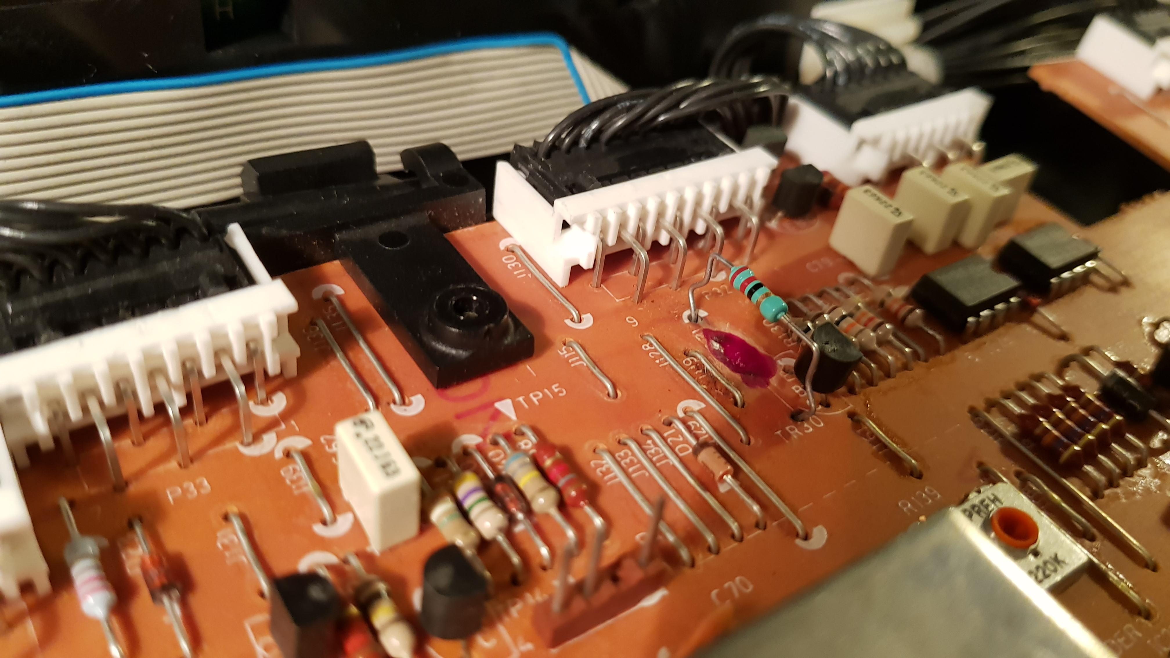
Hardly could remember but there was a kind of smell in a Beocenter 9500 came from Resistor R131 on Board No. 20.
The PCB was burned, scrached it all away and coated it with some Nailcoating from my wife ( be quiet don´t tell her ;-))
It´s a 22 Ohm Resistor and in my opinion the resistor should limit the Current through the Motor.
As in your case there was nothing wrong with the belt or drive, mounted a new Resistor on “higher legs” so the PCB is not blackened anymore. Mounted a new belt, Member Dillen has the right ones, don´t buy somewhere else some work some don´t, belts from Dillen working always.
Hope you´ll have success
Kind regards
Christian
Quiet right, there were discussions about that spindle, someone had a .stl file but sadly did not share for other users, maybe I’ve not found the right thread but if there is a file downloadable or PM please let us know.
Thanks
Christian
-
AuthorPosts


