Forum Replies Created
-
AuthorPosts
-
 BRONZE Member
Hi
Yesterday the foam surround from “Good Old HiFi” NL arrived.
So I started to refoam the 4 woofers.
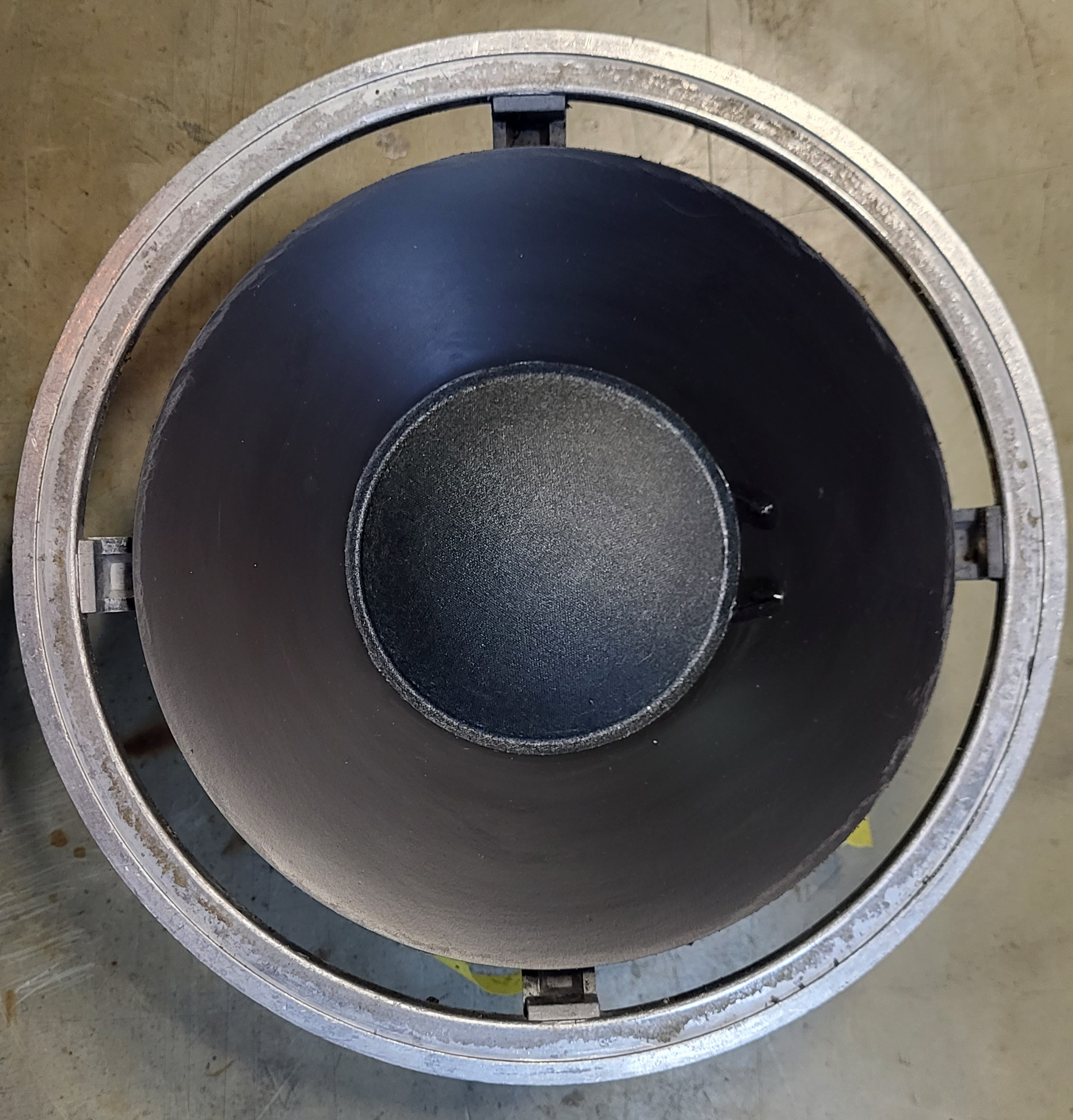
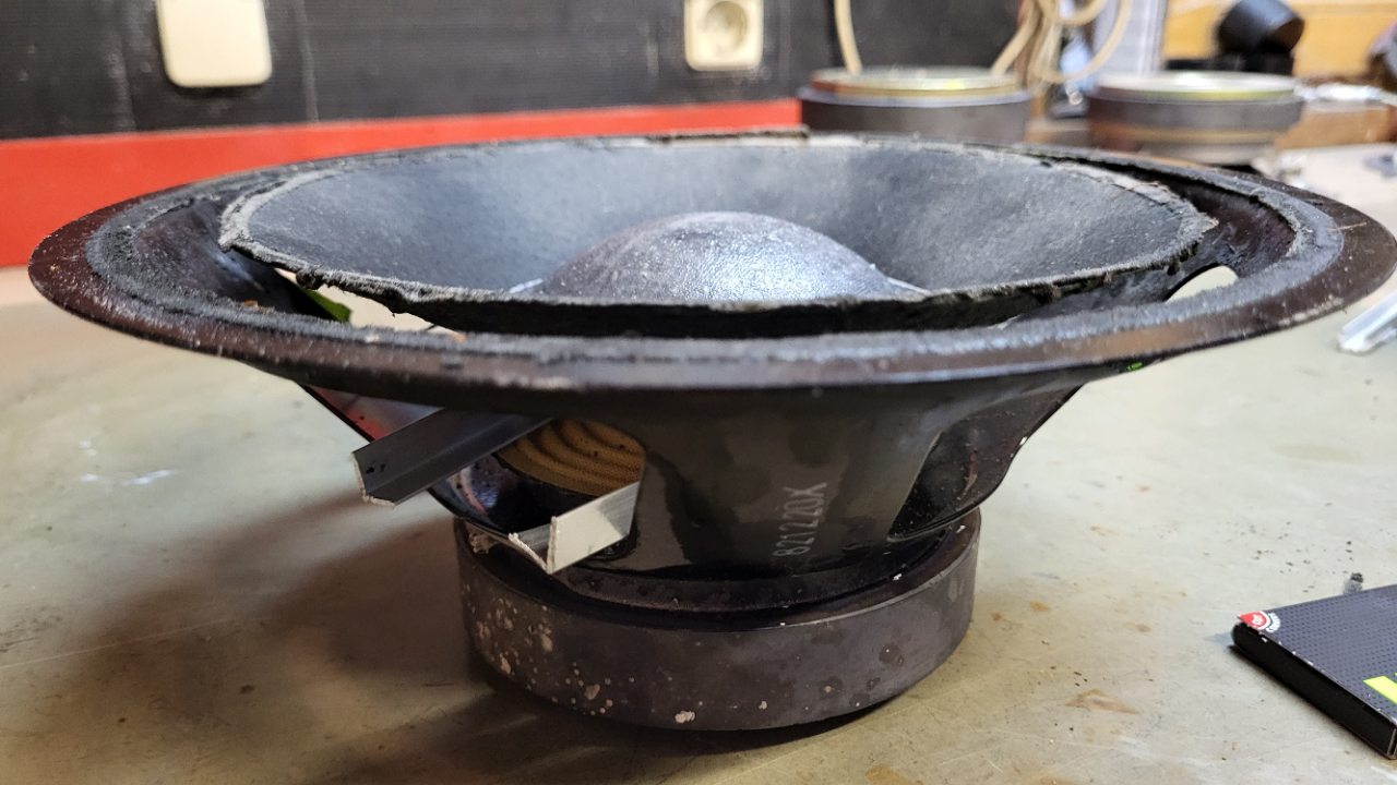
First I started with the 8″ woofer, cleaned the cast frame and carefully sraped the old glue from the plastic cone. My favorite solvent Mellerud glue remover made a good job.
Before:
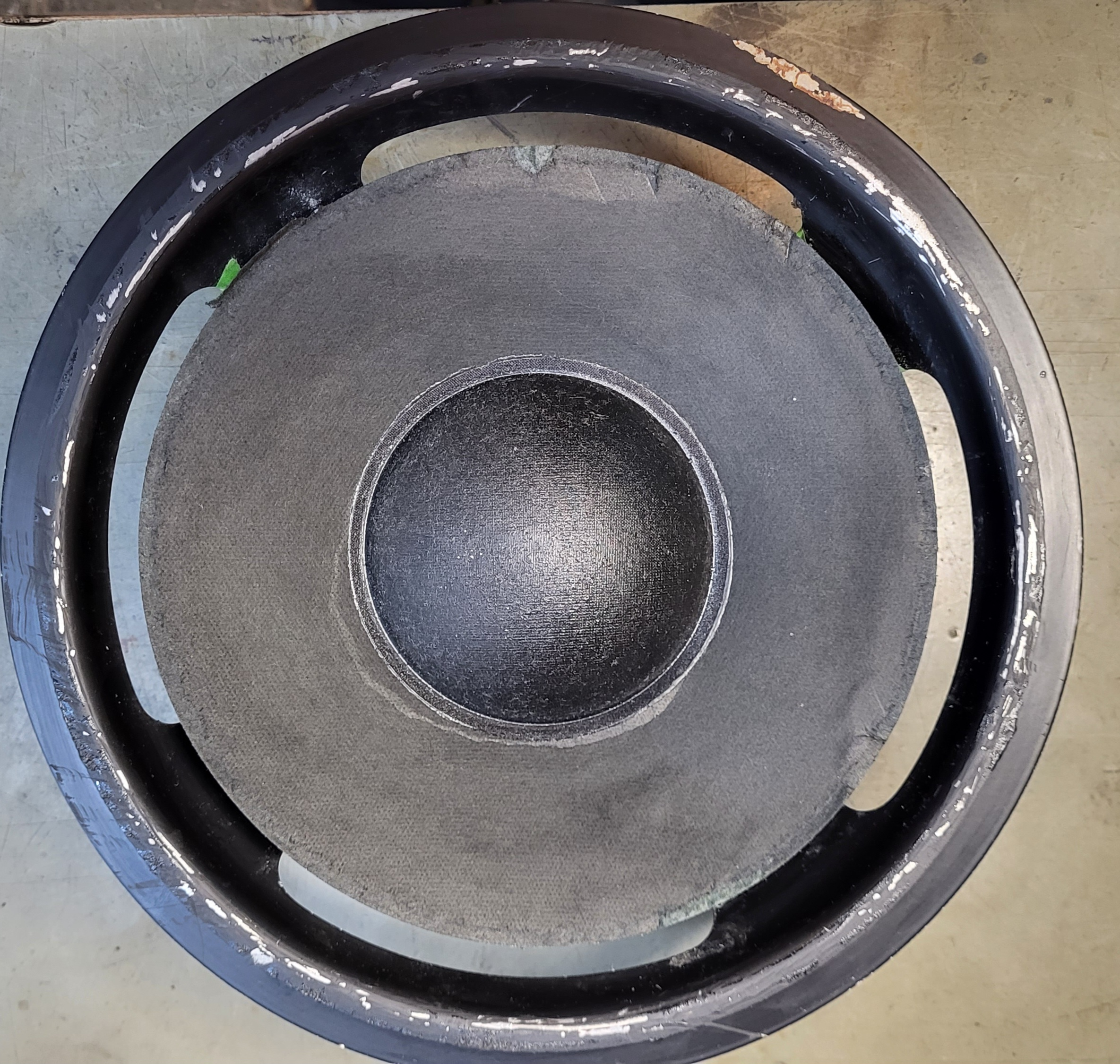
After:

After cleaning I glued the foamsurround as much possible centered to the cone. I’ve made a marking arround the cone to see how far the glue should be painted. Put the glue to the backside of the inner foam let it dry for about 5 minutes and pressed it firmly to the cone.
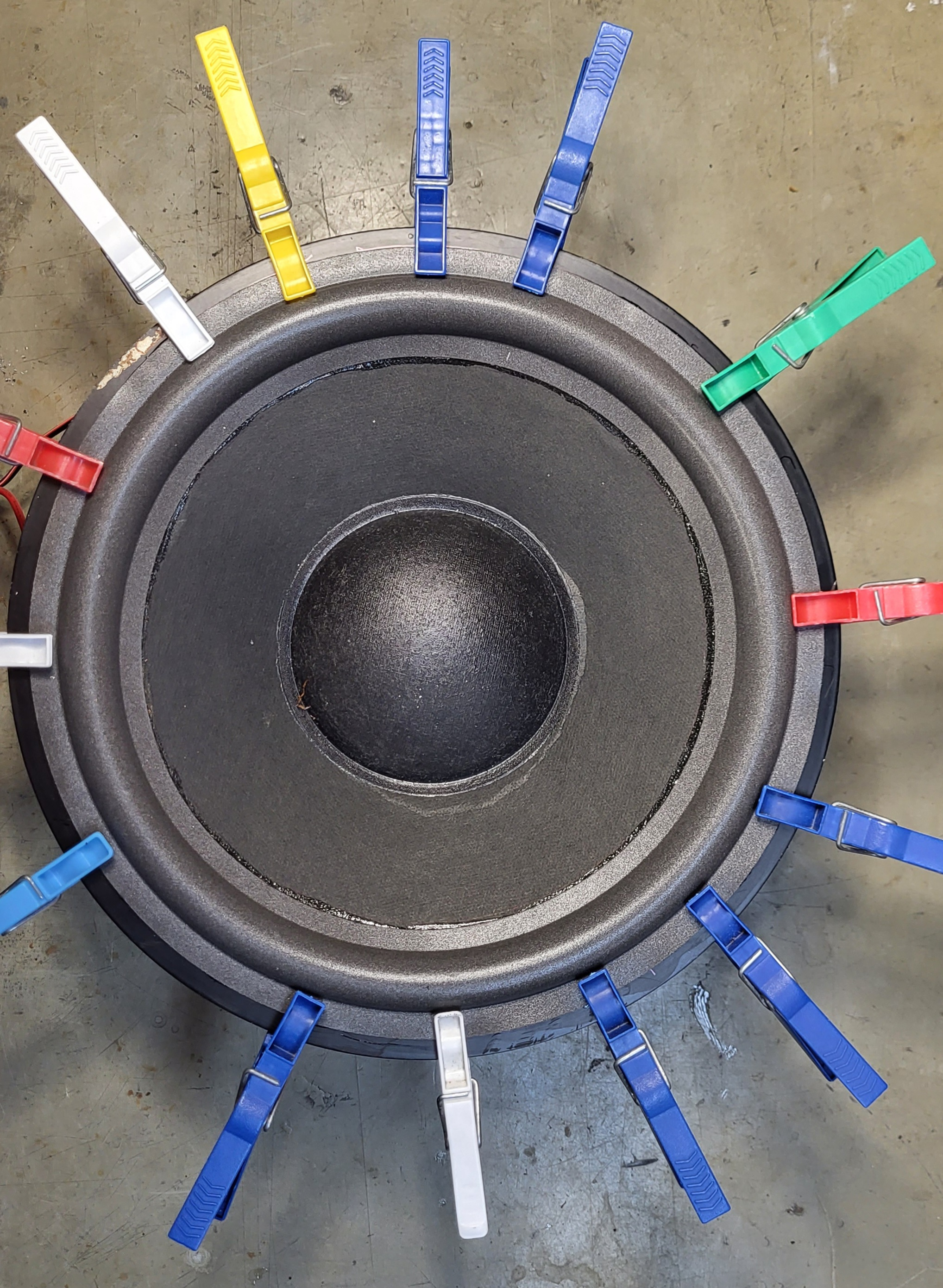
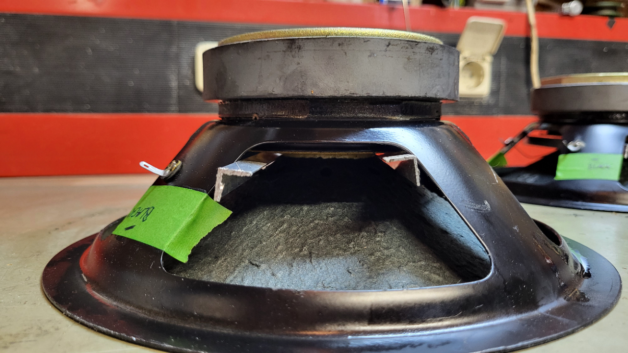
After that I clamped the outer foamring with clothpins to the frame and made a test with a conected amp and my mobilephone and the “Tonegenerator” app at 25 up to 50 Hz to hear if the voicecoil is aligned an centered. No adjustments where requiered. The 8″ woofers need no chimming in my case and I glued the foam to the cast frame. You could see on the last picture.
Up to the 10″ woofer.
I started with glueremover very carefully only on the old rotten glue because the cone is made of paper and I would not to get to much moisture into the paper.
After about 10 minutes I could peel off the old glue with my fingernail. There is a minimal layer of paper wich comes off with the old glue but that’s no problem.
As you cn see there is a damage left from the stick wich was mentioned in the first post. The new foam surround covers exactly thes damages so I’m happy. ;-))

Next was the same steps as the 8″ woofer, I glued the foam to the cone , tested with clothpins and made a marking around the outer foam to know where the foam has to be glued on the frame.

The cone centered itself like the 8″ woofer, no alignement nessesary.
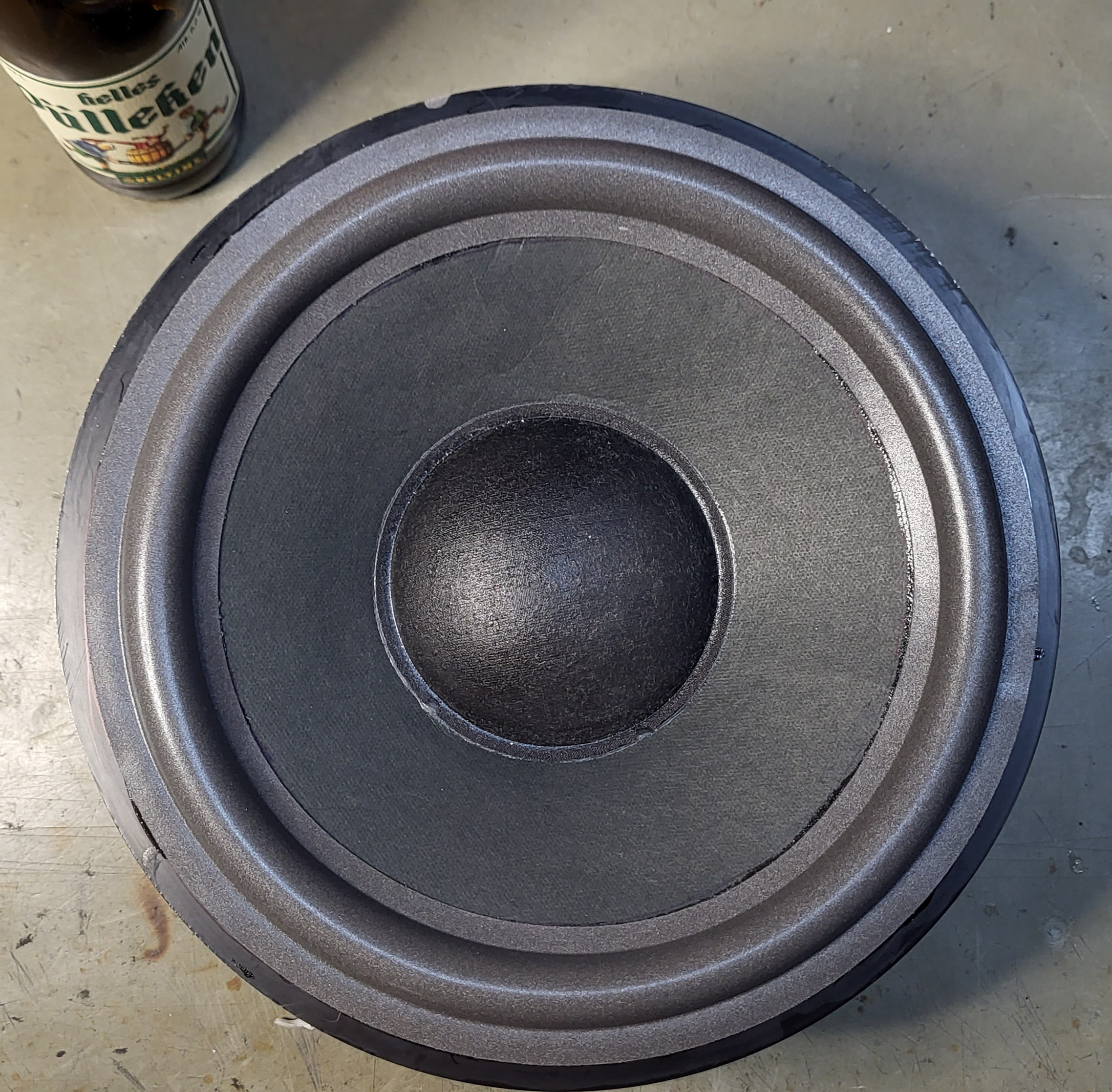
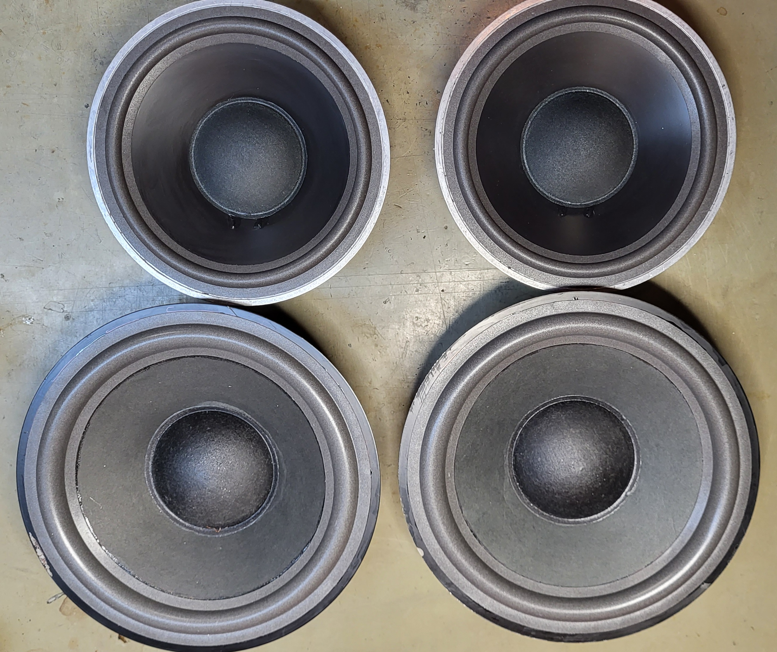
Here is the result: cheers;-))

Complete set of woofers after 5 hours:

Thanks for watching!
Next is the renew of the fabric grilles, new capacitors on the filterboard and refreshing the wooden case.
Kind regards
Christian
Hi
In between I dissassembled the 8″ and 10″ woofers from the cabinet.
The coils are measuring all good so far.
I decided to bring them back in shape as following:
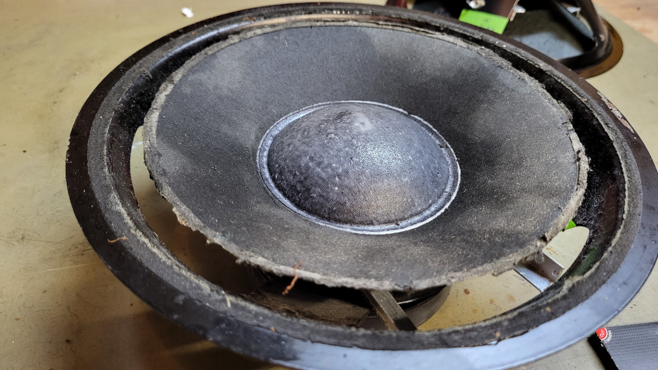
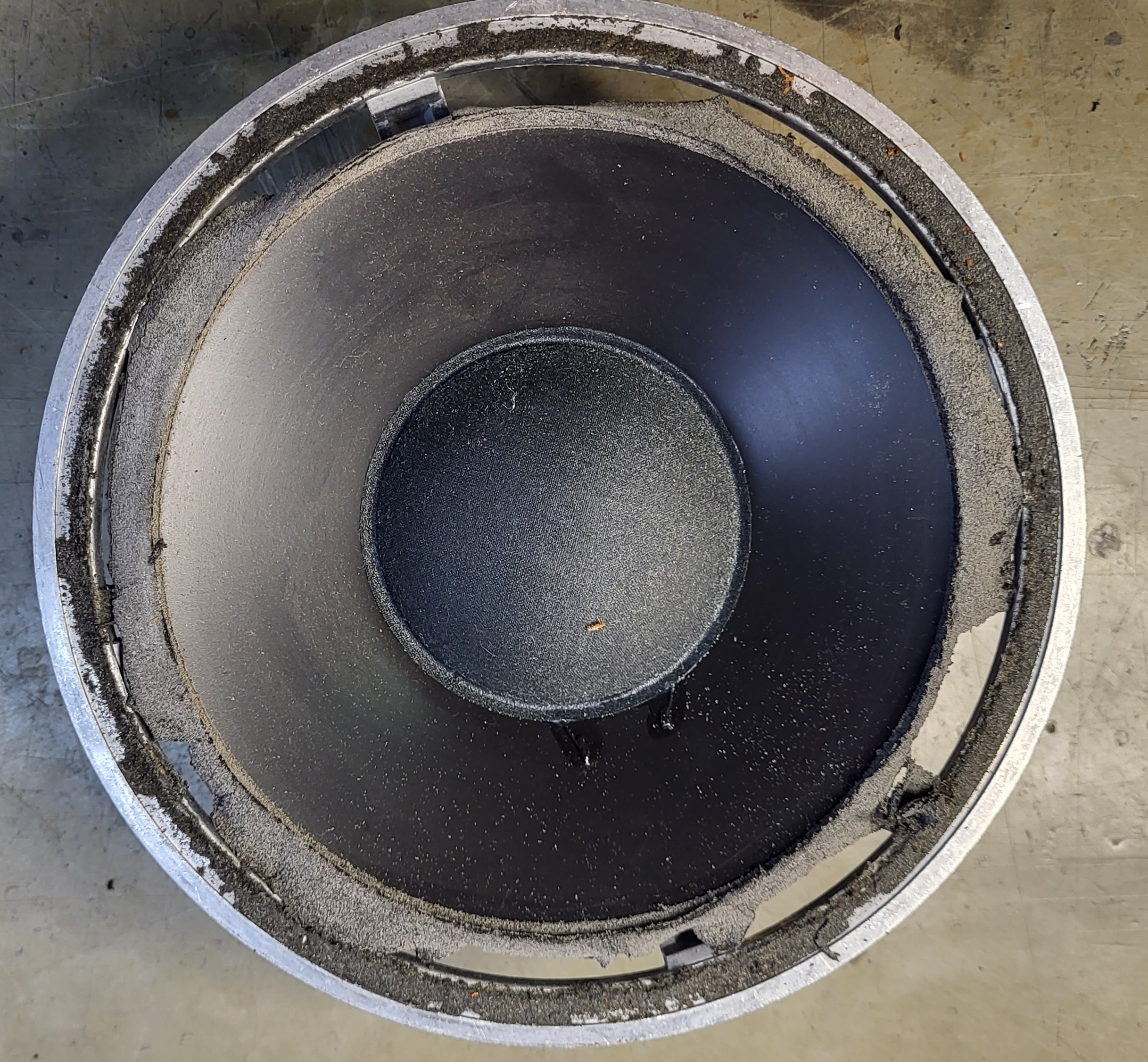
Took some aluminium profiles 10X10 mm and put them underneath the cone to lift the cone upards about 1 cm above the metal frame.
Sprayed with a small amount of water front and back of the cone and let them laying cone downwards on the table over night.
The weight of the chassis gave the right amount of pressure to the cones and next day it looked very good for me.
on the picture you could see the result.
Does anybuddy have a good source for the front fabric? Mine have some small holes and not looking good anymore.

Still a little bit dirty but that will be no problem so far ;-))
Waiting for the foam surrounds…..
Kind regards
Christian
Hi
Thank you for the helpful hints.
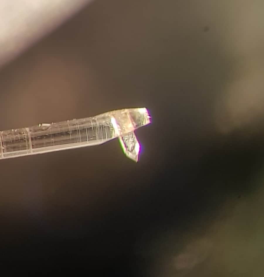
For me it looks like the stick has left two dents in the paper cone while it was there for several years and I’m not sure how to bring the cone back to shape, maybe with hot steam.
I will take out the speaker next days, foam surrounds are already ordered.
I give more information after that.
Regards
Christian
Hi
Looks like the Beogram and the Beocord need some restoring.
Beogram: All capacitators, resoldering of contacts and adjusting the << >> buttons, new tangential drive belt.
Beocord: Most all capacitators and cleaning the cassette drive mechanism, new belts.
Ask for someone near you who has some experience with B&O gear.
Regards
Christian
Hi Alf
Maybe you let all others know how you managed the deal with the stepped pulley.
regards
Christian
Hi
Normaly the CD shold work with the new caps. Recheck the polarity of C 2103.
Maybe you have to readjust the laser current.
Could not find how to in the Beocenter 9000 SM but similar in the Beocenter 9500 SM page 5 14.
On page 5 13 you’ll find the points where to connect the DVM. Measure 50 mV and adjust with R 3106.
Carefully turn the pot, the current changes quick in both directions.
Kind regards
Christian
Congrats!
“WISE GUY MOD ON”:
When you used shrinking tube at the reservoir caps, why did you not put it over the soldering?
It’s a 4700 uF, keeps a lot of power inside when you touch chassis ZAPP!, don’t ask me why I know ;-))
I’m missing the clamp for the cap, maybe with some feltpad underneath to get it tight fit.
I would have mounted new pots on the mainboard while I have the unit already open. The speed trimmers could be precize spindle trimmers so it’s easy to get the right speed at 33/44.
“WISE GUY MOD OFF”
Kind regards
Christian
Hi
When you try to set the idle current measure the voltage at the speaker outlet
(speaker switched ON 😉 ) or L201 on power amp board.
Look for DC voltage more than 0.1 Volt.
Often had this issue, look if you get any variations when you try to adjust the OFFSET Voltage with R210. If not adjustable check TR201 to 205, best to desolder them because some of them are connected in paralel.
Seems that when you are through with this BM 6000 you can call yourself
CEFBM 6000 (certified expert for Beomaster 6000 issues ;-))
Regards
Christian
Hi
This is what I found in the old forum:
https://archivedforum.beoworld.org/forums/t/35376.aspx?PageIndex=1
Lot of information some pictures of the way the string goes.
Regards
Christian
Hi Luke
At first I would replache the CMOS battery, often makes problems. Even the other board works, could be working on the edge of battery life…costs not a big deal.
Second I would ask member Beobuddy for help, he’s able to write new eproms.
Regards
Christian
Hi
The problem with the keyboard could be a issue with IC 5 (STROBE) or the railvoltage for transistors T15 – 19 and TR 22. Look here for C 49 (1000uF)
These transistors should ” amplify” the strobe signal from IC 5, go to the LED displays and via resistors R3 – 8 to the keyboard.
The strobe signal is fed via the keyboard to the uPC IC 4 PINs 8 – 12
If there is no strobe signal present the keyboard won’t work.
Regards
Christian
Hi
Check all connections, pull out and reseat the DIN plugs.
Cracking on all sources?
Tuner too?
Switch connection CD to Tape input.
If present, hook a mobile MP3 player with an 3,5 mm to DIN jack to the eg. Tape input.
Please let us know what kind of speaker are connected (aktive via Powerlink or passive)
Common problem with e.g Beolab 4000 MKII is a crackling noise caused by a dieing ICE Power amp module.
Regards
Christian
Hi
From the distance it’s hard to sort out what the cause of the amps problem is.
Look for the service manual and start measuring the basic voltages comming from the power supply board.
Often the Beomaster 6000 came back to life when renewed the caps on this board, can happen, must not.
If this did not help it seems that you have to recap the complete amp including the poweramp section. There are new precise trimmers for the idle current and offset highly recommended.
I’m not shure what happens if you pull the plugs from the keyboard and try to switch on with your terminal remote, never tested this.
you should be a skilled hobbyist to perform these working on the amp, no work for “two left hands” ;-))
Kind regards
Christian
Thanks for information
Now everything is clear.
Hi Stephane
Never thought that this IC could be the reason , lesson learned.
Could you discribe what the cause of the problem was, e.g. PIN 21 CLP or PIN 22 SER DATA to ground? something like that?
Regards
Christian
Hi
There is no light or LED and really no signs of life on the BM 6000? No cklick?
Watch out your fingers , hope you are skilled for handling with life voltages, electronics and measuring.
Before opening the Beomaster:
!!!FIRST PULL THE MAINS PLUG FROM THE WALL OUTLET !!!!
Noone here in the forum is responsable for what you are doing at home on your own risk.
Sure there are fuses inside.
Exactly 2 of the fuses can be found near the mains transformator on PCB 11 (FUSES AND RELAY)
Download the service manual and you´ll find the right ratings for the fuses depending what mainsvoltage and what type of Beomaster you have.
Regards
Christian
Hi Alf
Voltages that you measured are OK for 33 RPM.
The relay is in off position when 33 is selected.
If you switch to 45 can you hear the relay klicking? With the new one go to next with your ear to the relay.
If 45 is selected the voltage at TR 6 should drop to near zero volt, as the relais should engage.
The relay is switching the resistor networks 1R8 to 1R13
The following part of the circurit is same for both speeds as far as I can see.
A further possible fault could be the caps to the motor 0C6 4700uF and 0C7 150uF BIPOLAR
A hint is mentioned : I’m not sure but the lightbulb 1IL1 is used for the start of wien- bridge, so check if the bulb is OK
Recapping is recommended.
Regards Christian
Hi
Seems that you have to open up the Turntable.
There are 2 screws on the right side to unscrew, then move the tonearm to the middle and fold the top to the left side up, always watching space between tonearm and topplate.
In the back of the topplate you should find a lever wich can be used like the bonnet holder of a car.
In the thread wich i already mentioned you’ll find 2 pictures how it looks original and a few posts later there is a picture how you could repair it wit a screw.
As you are Bronce Member you could download the service manual for further information.
Kind regards
Christian
Hi
Often the transport string is off. Discussed often how to repair with a simple screw.
Looh here for further information:
https://archivedforum.beoworld.org/forums/t/35376.aspx
Kind regards
Christian
Hi
It seems that all signals are present.
If you switch the beocenter on with the remote are the sensorbuttons working as expected?
You could compare the measured signals with the service manual page 7-8.
Pic 1: maybe a different timebase could be OK
Pic 2: ENABLE maybe a different timebase could be OK
Pic 3: KEY DATA seems to be ok
Pic 4: CLP seems to be ok
Did you measure 0 V at IC4 Pin 2 (RESET)?
What happens if you go to testmode by short circuiting the TESTMODE contacts on board 43?
-
AuthorPosts