Forum Replies Created
-
AuthorPosts
-
 BRONZE Member
As I already mentionee
d, it upon your amount of money you will spend for an build in RIAA.
I´ve not heard the one from Beolover but he´s always on top with his development and he makes a great job. He´s not just firing out some products but he is thinking and thinking about to make things better , my opinion an many others I belive.
What I heard about the Zen Phono preamp was that it is a very well made and sounding RIAA, but even this one I´ve not heard.
The Claudius product seems to be grounded on the RIAA from Beogram 4500/ 7000 with some silde variations here and there. He´s doing a fine Job too and will help you kindly and friendly with problems related to his products if you have problems. I´ve had no problems so far.
So there are are mountain of RIAA´s to look for and the choice is yours.
For the external RIAA´s check the several HiFi and HiEnd related Forums. There you can read years and will not find the right one 😉
That´s all from me to say, because it will end in a endless thread ;-))
Put the needle on the record and dont talk about it , listening is believing;-)))
Kind regards
Christian
Hi
Some suggestions about buildt in solutions for Beogram 4002 / 4004/ 6000 :
The solution from “Beolover” is very impressive, plug and play you can buy it on the E-B …. auction platform, search for:
Beogram 4002 and 4004 Phono RIAA Pre-Amplifier – Easy No Soldering Installation.
For more information look on Beolvers Blog.
Have not heard it so far but there are some points where you could adjust the RIAA to you favorite sound I guess, would be very interesting in my opinion.
The second solution for a build in preamp is like this from danish Soeren Claudius:
https://claudius-elektronik.dk/designs-og-l-sninger.html
Have alredy mounted 5 of these for several projects and it’sworking great.
A little bit of soldering needed but no big deal and a good value for the money my opinion.
The third I know about is from Jacob Rungwald, member of facebook group Beogram 400/4002….
https://www.facebook.com/groups/1499233306805847/permalink/6809783595750765
This is a plug and play RIAA version and has implemneted a IR remote function via DataLink
(Beomaster 4500 or similar is needed) so you could controll the Beogram with a BEO 4, Beolink 1000 or similar.
You have to get in touch with Jacob and ask for avaiability and price.
Thousands of extern Preamps a avaiable quality from crap to high end, like the prices from a few Bucks up to somewhere ;-))
So it’s your choice
Kind regards
Christian
Hi
You are right, the spindle is held by a rivet and only to remove with some pulling on the rivet
I’ve a complete spindle / hub in my workshop, all teeth are ok, rivet is attached send me a pm.
Kind regards
Christian
Hi Gertjan
For me it looks like the linkagearm or the damper is stucked. Did you clean these too?
The damper has a screw to regulate the incomming air (shown in the video at about 8:00)
Maybe you open this “valve” one turn to the left to see if the damper is moving.
Keep us informed if you got any progress.
Kind regards
Christian
Hi Alf
The felt pad or whatever you took should fit not tight into the groove. Check if the idler runs nearly free when you spin it with the finger in both 33/45 RPM without motor. The size of the felt pad is critical, a little bit too big and it would slow down the idlerwheel significantly.
The stepped pulley is nice and clean?
Btw, had a knocking noise when the shaft of the motorchassis was hitting the speedselector shifter bar (part No.35).
The chassis has to be aligned that the shaft is in the middle of the gap. Have a closer look in this area. You can align it by turning the washers that hold the springs of the motorchassis.
There should be no contact from any parts to the main chassis.
Look page 13 of SM ( Beogram 1200) “the most frequent cause of motor noise, hum and rumble in the Beogram 1200 is defect in the mouning of chassis and motor……”
Hi
As far I can remember is that when you put 2 caps in a row you have to double the capacitance.
I would try two 47uF in row. +–+
The brake circurit has to be checked too.
Check TR21 TR32 TR33 and the value and polarity of C 43
Let us know if you got any progress
Kind regards
Christian
Hi Alf
The brass tounge has to sit in the groove tha s right. At the tip of the tounge is a kind of feltwasher, sometimes missing.
Where did you get the “new” idler wheel?
If you got yours from Martin (Beoparts) the new wheel should run quiet. These wheels are made very well.
Did you mount a new belt? If not order one from Martin he provides the right ones with the right specs. Do not buy any from E-B…. No orange silicone ring.
Hope that helps a little bit.
Kind regards
Christian
The things in the motordrive are working all together.
Hi….? What´s your name?
There are different versions of motors in the Beogram 1000.
Rectangular motor housings like Beogram 1200 have a conical stepped drive pulley where the speed is regulated via the smaller knob at the speed selector. The motor axle is lifted or lowered via a plastic gear underneath the motor.
Motors with a round housing have a straight stepped pulley where, a so called “Eddy Current Brake” is implemented. The brake does what it´s called, the motor runs without brake too fast and you have to adjust (lower) the speed with the same smaller knob at the sped selector.
Often this knob is seized from hardened grease and has to be disassembled, cleaned and oiled again.
A picture from underside of the Beogram without lower wood cover would help.
Indeed these Turntabels have to be renovated after abou 50 or 60 years.
Fresh oilinfusion for the bearings or some new Bearings from Beoparts.dk would help, but you have to know what you need so have a look inside.
Kind regards
Christian
Hi Mike
Send me a PM, I’ve a 3d printable .stl file for you.
Kind regards
Christian
Hi
First hitting and bumping these amps seems not a good idea for a repair ;-))
For me it sounds like a cold/broken solder joint.
You said that all sources are involved so there seems to be a problem in the output section of the tonecontrol or the input of the poweramp.
Look for the tonecontrol PCB 3 there are all sources connected and the output to the
poweramp PCB 9.
Look at the output connectors PCB 3 and input connectors PCB 9 for cracked solder joints.
If necessary resolder them, but disconnect from mains before you start, I can tell you: do not solder in a runing amp and don’t ask me why I know this:-))
More BANG than Olufsen
When you change the volume with no source connected is some crackling audible (VOL Pot)
The other problems you discribed seem to have another source on the uPC PCB 2.
There are a lot of connectors which can come loose from hitting and bumping or even cold/ cracked solder joints.
These cold solderjoints are a common problen on these and other B&O gear of this age, but not only related to B&O gear ;-))
Is the poweramp cooling fin getting hot?
The fins should stay handwarm even after 1 hour idling with no signal.
The cooling fin of the power supply PCB 16 are normal gettin hot about 45 to 50 Celsius.
Did you alredy recap the PCB’s (PCB 9) and did you renew the trimmers on the poweramp PCB?
Did you adjust the no load current and the offset of the poweramp?
Only a few hints…let us know if you had progress.
Kind regards
Christian
Hi Adam
Maybe there is a 2nd counterweight missing.
If you look on page 4.3 in the SM Beogram 3400-1900-1100 there are two of them.
1 the one you mentioned Part Nr 52 Counterweight
2 that maybe missing Part Nr 63 Counterweight
seems it is connected to Part Nr 60 pointer ( slider)
Kind regards
Christian
Congrats, issue solved
Hi Alf
Do I understand right? You are measuring 6 V at C of 1TR 20 and 2 Volt at SI on the mainboard?
If so it seems that you have a broken trace between these points.
SI is connected to several IC’s on the logic board under the button plate.
Have already had broken wireconnections b etween mainboard and logicboard, maybe you have a closer look there.
Kind regards
Christian
Hi
In between the speakers moved to my livingroom and I’m sure that I don’t need a subwoofer anymore. In this moment they are connected to my Denon receiver with all tonecontrol turned off and the sound is very impresive, nothing is missing, no boomy bass just controlled but very deep.
The adjustmentscrews for tilting the speaker were too long, cut them about 25 mm and now the speakers are tilted in a for me good looking way.
The Beomaster, Beogram and Beocord will come the next week into business.
In the moment i don’t really see the MC 40 cabinet in my living room, in my taste it’s too high (about 63 cm) plus the Beomaster 8000 on top, together nearly 80 cm.
Maybe someone could make me an offer for a Cabinet SC 80-2 ;-))
Now to the fabric.
I started with gently prying out the aluminiumtrim, possibly with not bending too much because the corners are cut to 90 degrees and only a tiny part of material is left on the edge.
Two corners were broken during disassembling ;-((
I pryed off the old fabric and tried with a smal part of the new fabric to get it into the frame and push the aluminiumtrim in to clamp the fabric in place.
No chance, the fabric seems to be to thick.
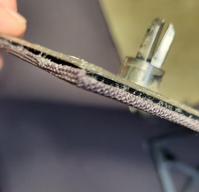
I had a closer look to the original mounting of the fabric and could see that the fabric is only bent around the edge to the slot where the aluminium fits in.
The first attempt just to spray some glue on the frame and pull the fabric in place failed because you glue to the front and the fabric comes to a wavy looking on the edges.
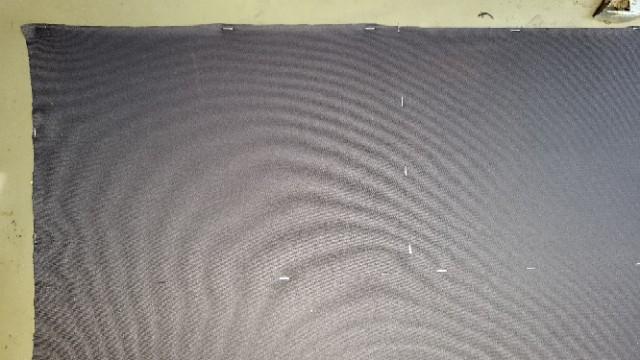
After a bit headscratching how to get this done I decided to prestretch the fabric on my table with some staples like in the picture below. (Fabric face down, staples about 35 X 30 cm)
The pattern is caused by camerasolution.

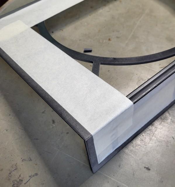
I masked the frames with painters tape to get the sprayglue only to the front and the edges:

waited about 2 minutes to let the glue getting sticky and pressed the frame to the fabric.
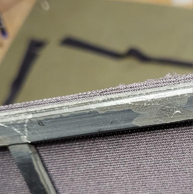
Than I took a square profile weling wire of 2,5 mm and cut with a razorblade a straigth 2 mm excess.

This excess cam be layed around the edges and pressed into the still sticky sprayglue.

After that the aluminium trim could be reinserted snugfif and looking good.
The broken corners of the aluminium don’t matter, hardly visible from 1 m distance.
Did not take further picture yet, comming soon.
Kind regards
Christian
If you really must have a video, here it is:
Hi
First, F1 is blown because D20 was shot.
D20 is a protection Z diode wich makes a short circurit to ground when the voltage rises above e.g. 6,3 volt to protect the uPC.
I’m not really sure but for me it looks like the reset IC1 PIN39 should have low level.
I would recheck TR17 and C20 and D15.
Maybe member Dillen has a suggestion about the reset state at IC1.
BTW:
Did you recap the Beogram or did you resolder the solderjoints of all plugs so far?
Lot of trouble comes from these failured caps and dry solderjoints.
Kind regards
Christian
Hi
The problems you discribed are mostely caused by the rotten foam inside the speakers.
There is a PCb in the lower section of the speaker with the relay circurit, the most lower copper traces can be solved by the rotten foam and must be renewed with e.g. some wire soldered to the start and end solderjoints.
Further information about disassembling you can find here:
Look for these traces:

Any questions? let us know.
Kind regards
Christian
As I already wrote, the speakers sounding absoloutely amazing.
Far different from the M 150 of course more deep bass.
Have the MC 120.2 in another room, did never expect such a good fundamental sound, missing nothing.
Next day I hope to compare with my Nubert Nuline 102. It´s not a real comparison 😉
Now it´s time to say goodby to my 5.1 set and switch back to stereo with Beomaster 8000, Beogram 8000, Beocord 9000, Beovox MS150.2 and a MC 40 cabinet.
Maybe I connect a pair of CX 100 to the secondary speakeroutlets to have a “rear speaker”.
Have a nice week
Christian
Hi
What I would do is to open the amp again and have a close look where the tabs should go.
Maybe a part of the wireharmes in the way.
The shielding plate over the uPC is in it´s place and all the way down? All metaltabs of the plate are outside?
You could stand the amp like an open book on it´s side so you can better see and feel what going on.
Put somthing under the amp to not damage the wooden frame.
Usualy push from below in direction of the display and push down the lower edge and let it snap in.
Regards
Christian
Hi, here are some news…
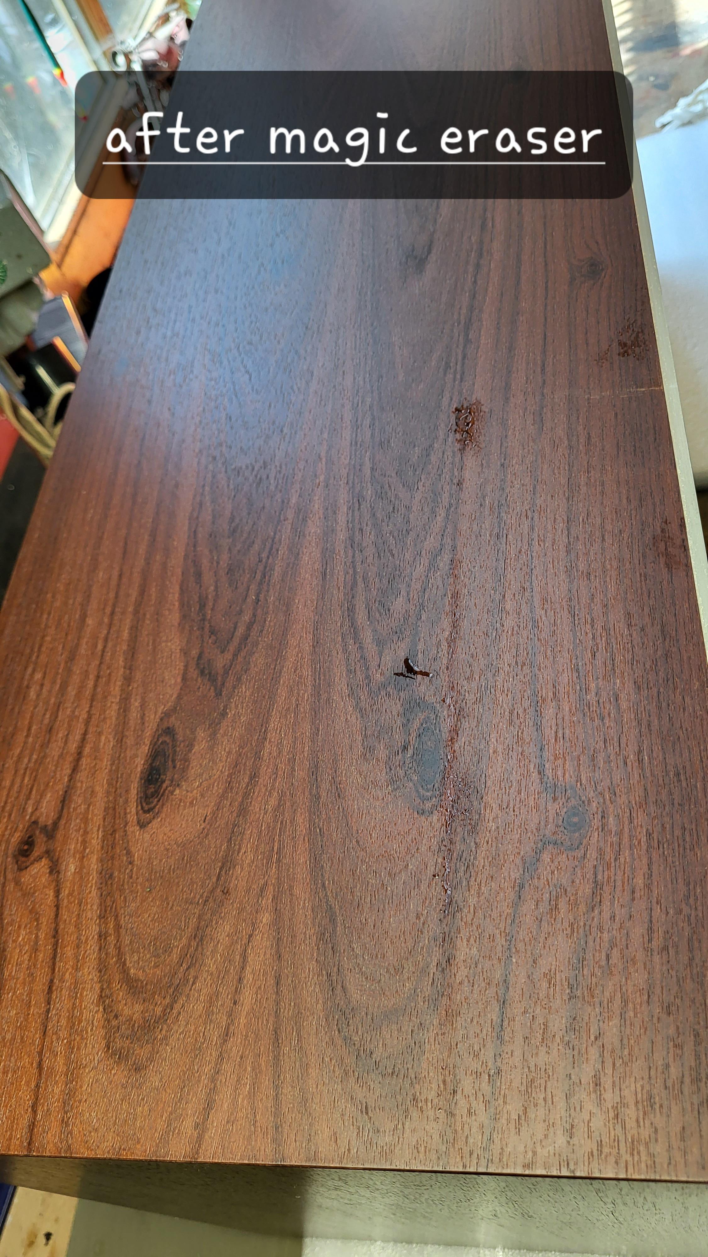
I cleaned the wood with a magic eraser and a light soaped water with a neutral soap.

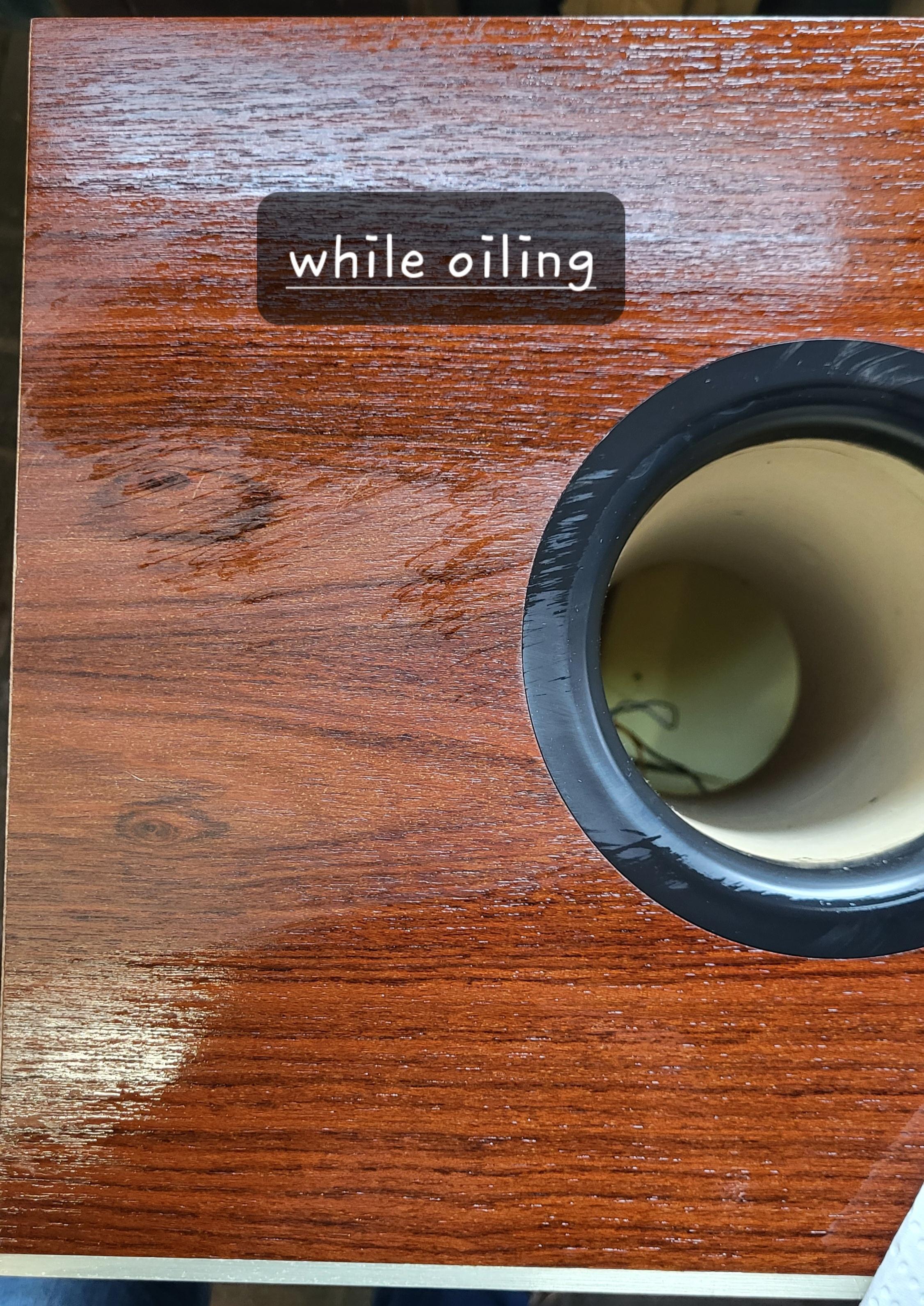
After letting it dry I put some renovating oil on the wood and let it shine again.

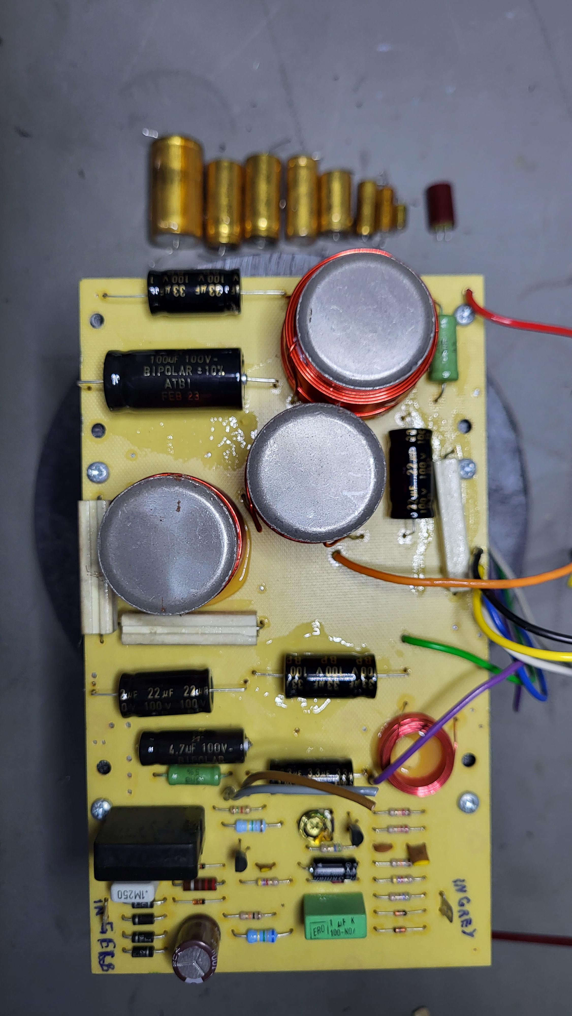
I recapped the Crossover network with new bipolar caps, just business as usual, old ones out new ones in.
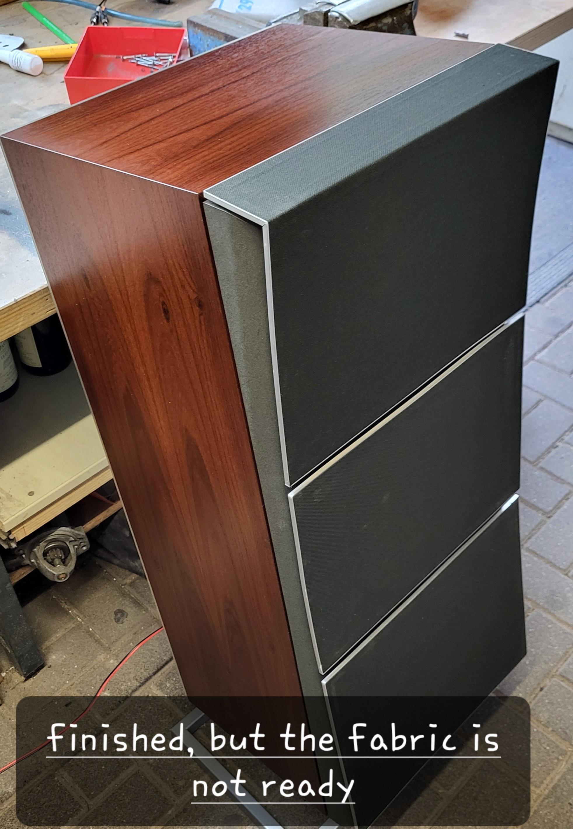
After that I assembled the chassis into the front frame and made the wireconnections to the speakers.
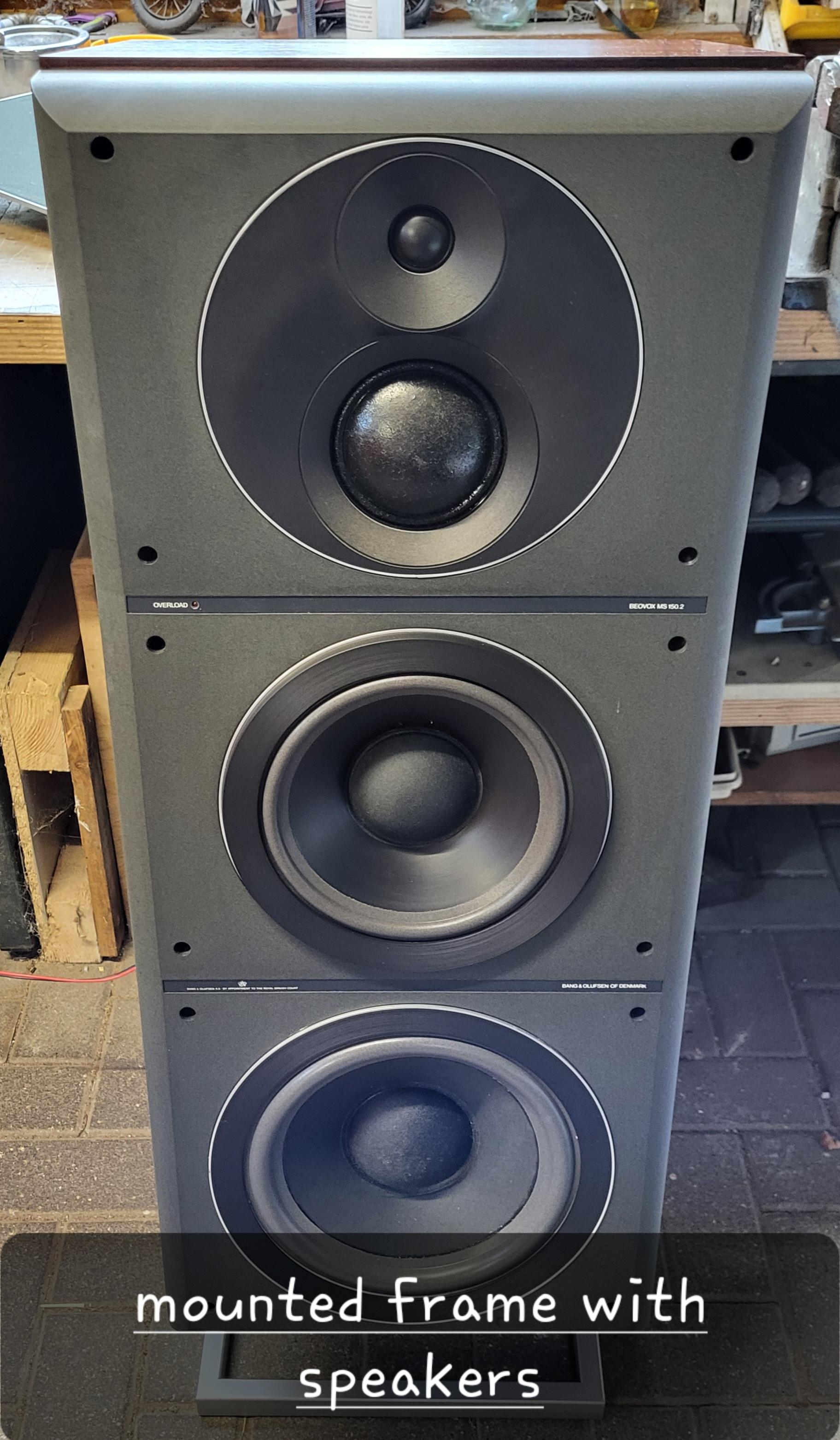
Mounted the frame to the speakers and made a testride.
Wow that sounds absolutly amaizing.
Here is the not really finished speaker, fabric was not delivered today 😉


-
AuthorPosts