


Home › Forums › Product Discussion & Questions › BeoMaster › Beomaster 6000 Power-On Issue
- This topic has 70 replies, 8 voices, and was last updated 1 year, 6 months ago by
 Jorgr Alvarez.
-
AuthorPosts
-
7 August 2022 at 09:51 #36685
 GlitchBRONZE Member
Hello,
I have a Beomaster 6000 Type 2253 that will not power on. I’ve been debugging this receiver for a few weeks now and not sure what to try next. I’m hoping that one of the experts on this forum can provide some sage advice.
A bit of background… I bought my first B&O equipment back in the 80’s, a Beomaster 8000, Beocord 9000, and Beogram 8002. I thoroughly enjoyed this equipment for many years. Unfortunately, I experienced my share of equipment failures. At the time, I didn’t have the time to repair the various equipment. Instead of paying someone else to do the repairs, I would just buy a used replacement on eBay. Some the replacements also had issues and I repeated the process. I now have a pile of broken, vintage B&O equipment and the time to repair it. I’m starting to work through the pile, piece by piece, repairing/restoring the equipment.
My current project is the BM6000. I can’t recall the exact details of how it failed. My best recollection was that the actual failure was much less spectacular than some of the other equipment (no smoke or loud noises). One day, it simply did not power on.
What I’ve done so far:
1) Replaced the pots and bad caps on the main amp module (board 9). Adjusted the no-load current and output offset. Tested the amp board out of the chassis powered by bench power supplies. The amplifier seems to be working very well.
2) Replaced the caps on the main power supply (board 16). Resoldered all of the connector pins. Adjusted the 6.5v output. Verified that all of the output voltages are the correct value. The main power supply seems to be working properly. The voltages are all close to the specified values except for the +-50v rails which are a couple of volts low.
3) Resoldered all of the connector pins on the motor control module (board 6). Checked the output voltage for the CPU power supply. The CPU power supply is close to the 5v specification. I have not been able to test the motor control portion of the board beyond verifying that it will reset the volume to an initial position if I manually move the volume pot out of position.
4) Replaced the pot and caps on the microcomputer board (board 2). Resoldered all of the connector pins. Adjusted the CPU reset circuit via R89 per the procedure in the service manual.
5) Checked the remainder of the board for any obvious broken wires, cold solder joints, or visually failed parts. Other than a (now fixed) broken wire for the FM frequency counter(?), P7-board2 to P26-board8, everything appears to be in good shape.
6) Read or skimmed every thread in this forum (and archives) related to the BM6000 to see if anyone else had a similar problem.
I believe that my problem is with the microprocessor not starting properly. When I plug in the unit the display will usually show a “:.” (colon, dot) on the frequency display, a blank source display and the FM tuner lights will light. The receiver is nonresponsive any to button presses except for changing the tuner mode which changes the tuner lights. Occasionally, the tuner and source displays will have other random LEDs lit. Less occasionally, the relay for the +-50v rails will be enabled. When this happens, the receiver remains unresponsive to button presses, but will power down after a period of time.
I’ve tried to run the microprocessor board and button board (board 15) outside of the chassis by powering via bench supplies. I’ve been able to get it to progress to a “P” display by changing the timing on when and how fast the 5v CPU, 6.5v and 15v power supplies power up. The results of the bench power-up sequence are not reliably repeatable. What shows on the displays varies and the relay signal is inconsistent. The board appears to remain unresponsive to button presses.
I’ve check the CPU clock signal on pins 1 and 2 on an oscilloscope and it seems strong and at the correct frequency. Same goes for the FREQ COUNT and TIME BASE signals.
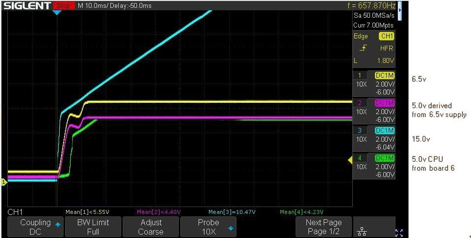
The next thing I tried was to capture the startup sequence of various signals. The Fig 1 plot below shows the power signals related to the microprocessor board. All signals are measured on board 2. The power signals are reasonably clean once fully powered on. Sometimes there is noise on the signals when the plug connection is made. This presence or absence of this noise doesn’t seem to affect the power-up results.

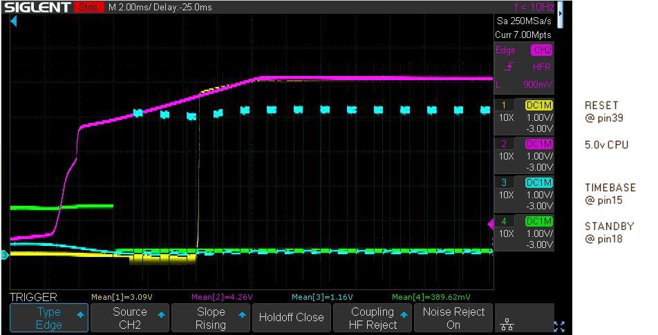
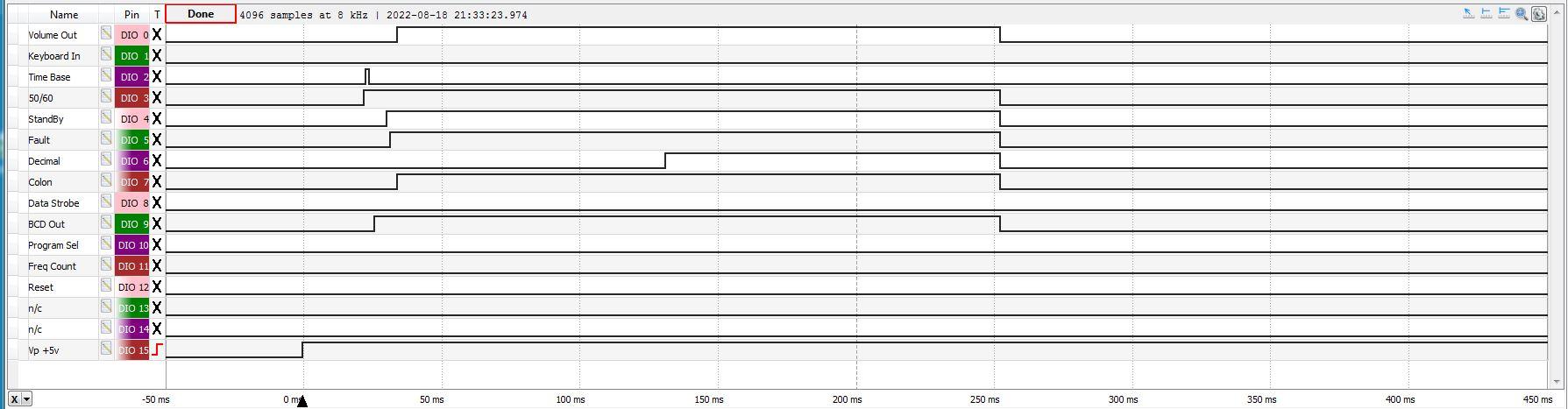
Fig 2 below shows various signals related to the microprocessor board. The CPU based signals start reacting after about 2.5ms after the power is applied. The STANDBY signal goes low and the CPU clock (pins 1&2) starts, feeding the TIMEBASE circuitry and the TIMEBASE signal is fed into the CPU. The RESET signal reacts as expected when the 5Vcpu signal goes high enough for stable CPU operation.

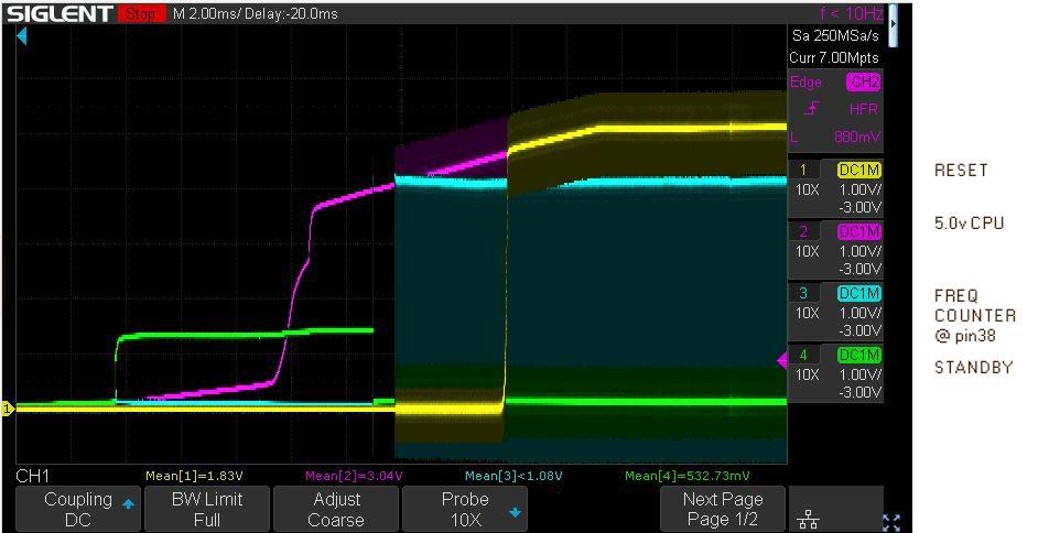
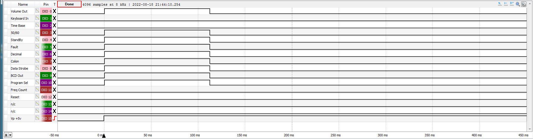
Fig 3 below is similar to Fig 2 except that the TIMEBASE signal is replaced by FREQCOUNT.

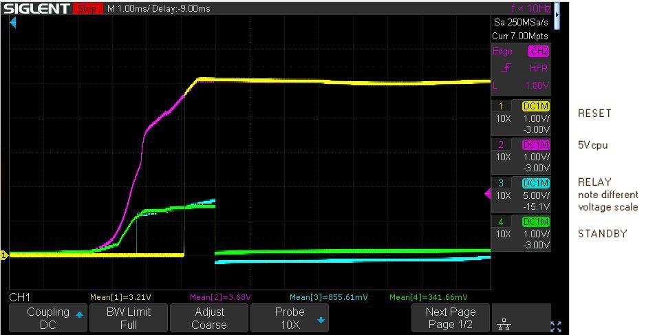
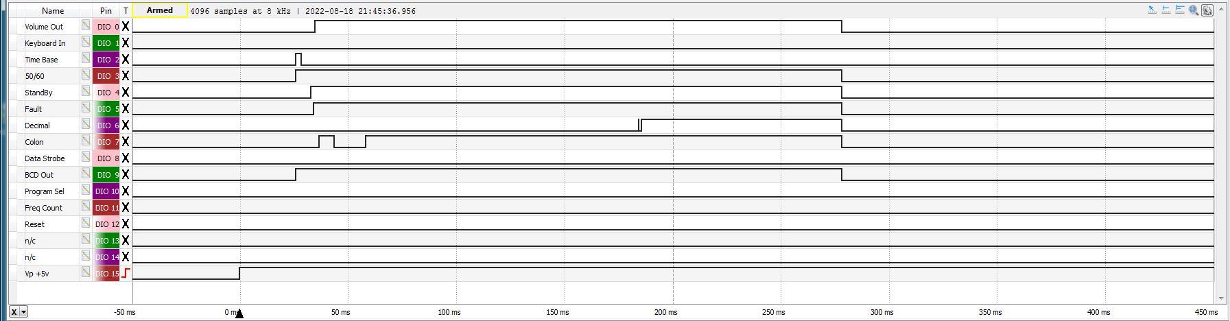
Fig 4 below shows the results of an experiment where I installed a smaller capacitor on the 5Vcpu supply to see if a faster voltage rise time would make any difference (it didn’t). The time scale of this plot is smaller than that previous ones. A couple of things that I noticed was that the time from power-on to the STANDBY signal going low is a consistent ~2.5ms. The STANDBY signal going low doesn’t seem to be related to the RESET signal. The RELAY signal tracks the 15v signal until the STANDBY signal pulls it low. Not shown in any of these plots is that the STANDBY signal also pulls down the FAULTSW signal when it goes low.

I’ve run many other experiments trying to determine if the microprocessor is actually running. I can’t tell if the CPU has failed or has detected some other fault and has halted. At this point I’m not sure what to try next. I would appreciate any help, ideas or suggestions.
One specific question that I have is whether or not the microprocessor board CAN be run outside of the chassis? In some of the archived posts, it appeared that it may be possible, but it wasn’t clear how it was done.
Thanks for reading this so far, hopefully any follow-up posts will be shorter.
Glitch
8 August 2022 at 09:59 #36686Hi Glitch
I’ve had a similar problem with a BM 8000 where the “SSTROBE” Signal wasn’t present.
If there is no STROBE no button and Displaywould work.
It’s only a small straw but maybe you check the Strobe Signal around IC 5 and the corosponding Transistors TR 15 – TR 22.
Kind regards
Christian
8 August 2022 at 18:09 #36687GlitchBRONZE MemberChristian,
Thank you for the reply.
I just rechecked the STROBE (Digit Select) signals on pins 26-28. All three signals are always HIGH (+5v). The only time that they change is when I plug or unplug the receiver.
I’ve checked these in the past and expected to see them changing. My assumption is that all HIGH on these signals means that the display is either meant to be blank or that the CPU is not properly updating the signals. Since some of the other signals that I expect to change during power-up are not changing, like the RELAY signal, my theory is that the CPU isn’t running properly.
I think that the STROBE signals and the downstream circuitry is not broken since I was able to get the “P” display, as well as other LEDs randomly lit, when I ran the microprocessor board outside of the chassis with bench power supplies.
My interpretation of what I’m observing is that the CPU initially starts, then fails or stops at random times. What I see on the displays and other signals depends on how long the CPU runs before it has an issue. Of course, I might be having tunnel vision on this theory and would be happy to try alternative solutions.
What did you do to fix your STROBE issue on your BM8000?
Glitch
9 August 2022 at 10:44 #36688Hi
The Strobe issue on the BM 8000 was just a misaligned Pot R15 which has to be adjusted to minimum ~3.6 Volt, the Pot was turned the whole way down and the CPU did not recorgnized the too small signal below 3,6 Volt.
This Pot is not present in the BM 6000.
If you can’t measure any strobe signal there must be something wrong with the CPU, I think, but maybe someone else has a similar experience with the BM 6000 and can help with a good idea or with a used and working CPU for a fist full of $
Had already 2 BM 6000 which I could not bring back to life because CPU related trouble. Doesn’t mean that the CPU’s in my case were really dead, but after working on these for days and not finding the error I made a decision to sell them for spare parts.
It hurts to give these iconic units away but…..
Sorry that I can help you further.
Kind regards
Christian
9 August 2022 at 15:58 #36689GlitchBRONZE MemberChristian,
Your reply above is consistent with what I’ve read about the B&O equipment of this era. B&O was pushing the bleeding edge at the time and reliability sometimes suffered as a result.
I’m hoping that I can get my BM6000 to show enough signs of life that it is worthwhile to spend the time and money to do a full restoration. I’m still hoping that the issue is related to an overly sensitive startup procedure and it is just a matter of figuring out what it takes to make the CPU happy enough to keep running.
Thanks again for your help,
Glitch
10 August 2022 at 13:56 #36690I wish you really good luck and let us know if you got any progress.
Regards
Christian
16 August 2022 at 23:01 #36691GlitchBRONZE MemberI haven’t made any real progress on the BM6000. I’ve resorted to replacing diodes and transistors that I didn’t think were bad. The removed parts tested OK. I’ve been able to slightly change how the circuit reacts, but it is just a different version of random behavior.
The good news is that I’ve been able to get my Beomaster 8000’s working. I have one fully working and a second that works except for the FM display. I have parts on order to fully restore/repair these.
My next step on the BM6000 project is to run some experiments on one of the BM8000’s to see if I can learn anything about how B&O handles the start-up procedure, especially when faults are detected. Ideally, I would run these tests on a working BM6000, but since I don’t have one, I’ll have to make due with the BM8000.
I’ll keep monitoring this tread to see if anyone has suggestions on things to try and report if I make any progress.
Glitch
17 August 2022 at 06:07 #36692artigBRONZE MemberSeveral products from that time will go into standby or not start up if there is no signal from the 50/60Hz mains frequency. It should be on pin 16 of the microprocessor.
17 August 2022 at 19:07 #36693GlitchBRONZE Memberartig,
Thanks for the suggestion.
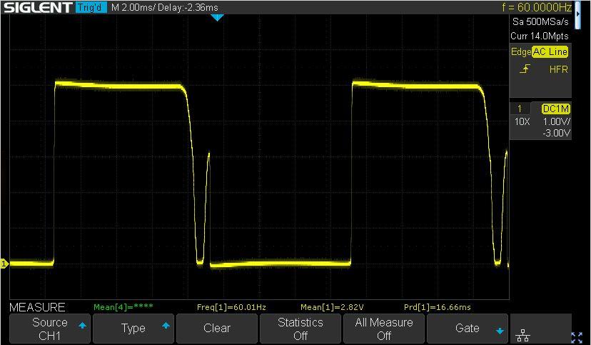
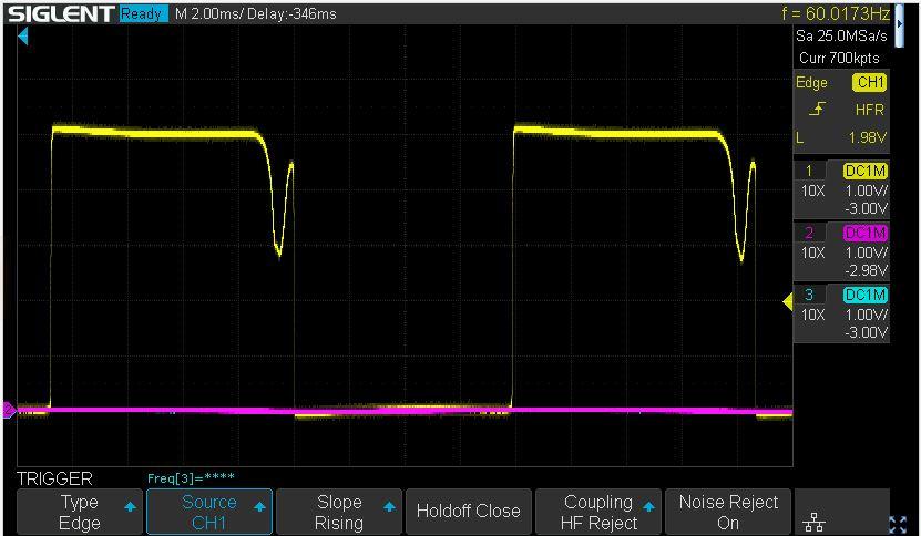
I checked the 50-60Hz signal fairly early in the debugging process. I saved a trace of the signal as a reminder to investigate an anomaly in the signal.

The extra blip in the signal is unexpected. My assumption was that the 50-60 signal would just be used for the timer functions and I would revisit this signal if the timers had issues.
I rechecked the 50-60 signal today and (initially) the signal constantly stayed low. I started to debug this and it “spontaneously” started to work again.
I ran an experiment where I decoupled the power supply (PS) from the CPU board by removing the pin P47-1 from the PS connector. I added a 10K pull-up resistor on the P47-1 connector side so I could check the PS circuitry. The PS circuit worked as expected except for the extra blip. I also monitored pin16 on the CPU. Sometimes pin16 would stay low, other times it would go high. The state of the signal seemed consistent with what was showing on the display. If the display got stuck at “:.” the signal seem to stay low. If the signal got to the “.” (standby?) display, the signal stayed high.
My interpretation is that pin16 on the CPU is pulled high as part of the CPU start-up process. However, I am having a difficult time determining if this is part of the CPU hardware initialization (standard output per the MK3870 datasheet) or if the software is controlling the pin state (direct output). This would only matter as a way of determining if the CPU is running. Pulling pin16 high makes the 50-60 signal “active” and the transistor circuit on the power supply will pull it low at at the appropriate time to make the 60Hz square(ish) wave. The CPU can then read the signal as needed.
I’m also trying to understand if the controller is faulted because the various signals are bad, or if the various signals are bad because the controller has faulted.
As a long-shot, I’ll try to get rid of the extra blip and see if that helps.
It would be interesting to see the source code for this. Then again, it is likely written in assembler and figuring out how it works would be a headache.
Glitch
17 August 2022 at 21:55 #36694GlitchBRONZE MemberI cleaned-up the “blip” enough that it should be considered high from a TTL point of view. This didn’t appear to make any difference in the overall power-up issue.
 18 August 2022 at 08:31 #36695artigBRONZE Member
Setting up all the I/O pins would be one of the first things done in the program after the oscillator has started and /RESET has gone high.
Pin 16 input is used only for the clock and for checking whether the mains power has disappeared when it tries to do a properly sequenced close down if it’s active.
The program was definitely written in assembler but I doubt if the source code still exists. For some information about the development of the Beomaster 6000 have a look at:
Also have a look at Appendix 8 and 9 on the same site.
19 August 2022 at 00:39 #36696GlitchBRONZE MemberThank you for the link to the BeoMicro webpage. I’ve read a few of the pages so far and find the site very interesting. I expect that I’ll eventually read the entire site.
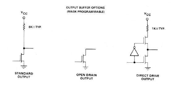
Regarding the BM6000 start-up, what the pins do at start-up may depend on how the CPU was configured when ordered. There were multiple options as shown in the diagram below from the CPU data sheet. Interestingly, on the Appendix 9 page of the BeoMicro site, the engineer comments on this topic.

I assume that CPU was configured with the standard or direct-drive output due to lack of external pull-up resistors (needed for the open drains) on the BM6000 board.
At this point in time, I’m just trying to figure out if I have a functional CPU versus a working CPU that is being faulted by something not working right on the board.
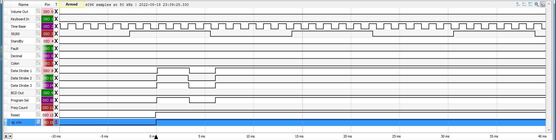
My latest experiment is to run the CPU on its own connected to a logic analyzer to see if I can learn anything from how the signals initialize or change. I would expect that direct-drive outputs controlled by the assembly code to behave slightly different than standard outputs. I may not learn anything from the experiment, but I’m not sure what else to try.
Glitch
19 August 2022 at 16:21 #36697GlitchBRONZE MemberI think I’ve been able to convince myself that the CPU is bad. I ran the logic analyzer test and the results were inconsistent. I expected that with a clean and simple test setup that the CPU behavior would be very repeatable. It wasn’t.
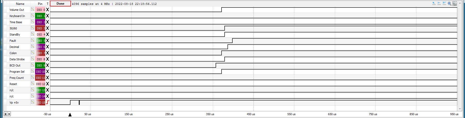
Below are a few scope captures with just power and ground connected and the various outputs monitored. The capture was triggered on the 5v power signal rising.
Most of the time I saw this…

However, other times I saw different behavior


The only consistent thing I noted was, at some (random) time, all of the signals would simultaneously go to zero.
I repeated the test with a 50/60 and TimeBase signals provided by a waveform generator. These results were also inconsistent.


I saw many other signal combinations. The only trends noted were that signals would not change after some (random) period of time and the outputs seemed to change in groups of four.
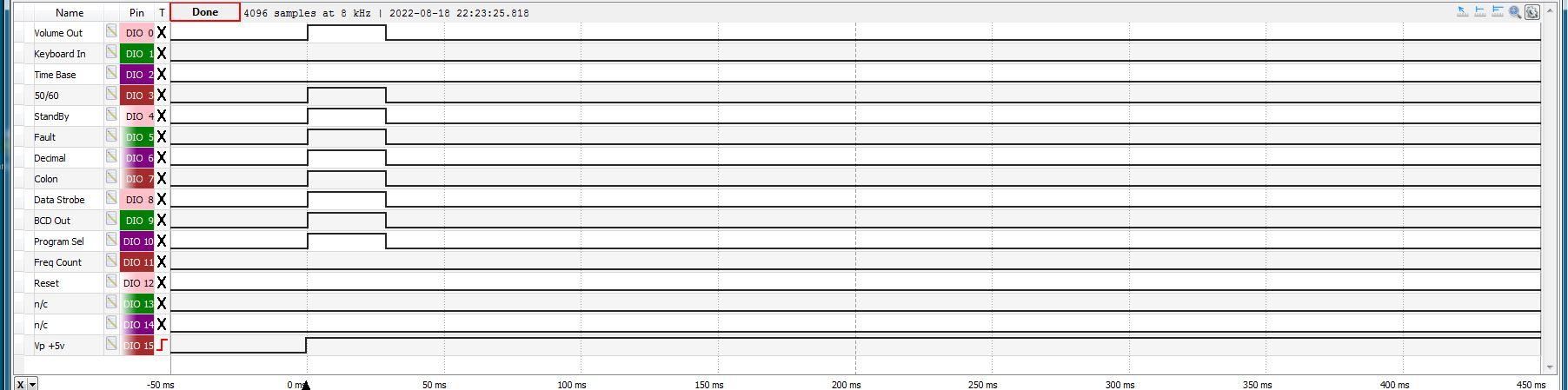
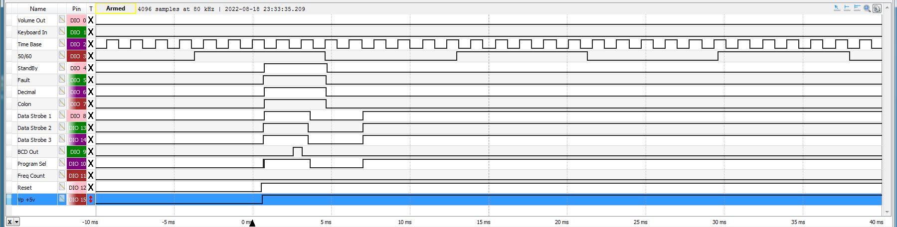
I also ran some traces to see if I could identify the output configuration type.

I think this plot tells me that the outputs are the direct output type and initialized by the software. I would expect the standard output type to all initialize simultaneously with the power signal.
Unless I get any more suggestions, I will give up on the CPU and move on to “plan B” for the BM6000
Thanks again to all that provided suggestions,
Glitch
20 August 2022 at 06:19 #36698artigBRONZE MemberDid you have a crystal oscillator on pins 1 and 2? The /Reset signal shouldn’t really be pulled high until after the 5V and XO are stable. It looks as if Reset goes high just before 5V, but perhaps that is deceptive.
Since the 3870 has no instructions for individually addressing the port pins it’s normal for all pins on the same port to be set at the same time.
I have an unused sample of the CPU but don’t have the means or equipment to set it up and test it. And I don’t have a Beomaster 6000 to compare signals, either.
20 August 2022 at 19:07 #36699GlitchBRONZE MemberI have tried running this latest set of tests both with and without the crystal. I removed the crystal and capacitor from the BM6000 board and used this for the external test. I have some reservations about running this in a breadboard setup, but it is what it is.
My logic may be flawed, but running without the crystal should give an indication of how the I/O initializes from purely a electrical circuit standpoint. With the crystal, I would expect to get an indication of what the software is doing. I don’t really know what happens in the grey area in-between the two, or if there is a grey area. My recollection is that microprocessors of this era just started running whatever op codes were stored at address 0x0000 when powered on.
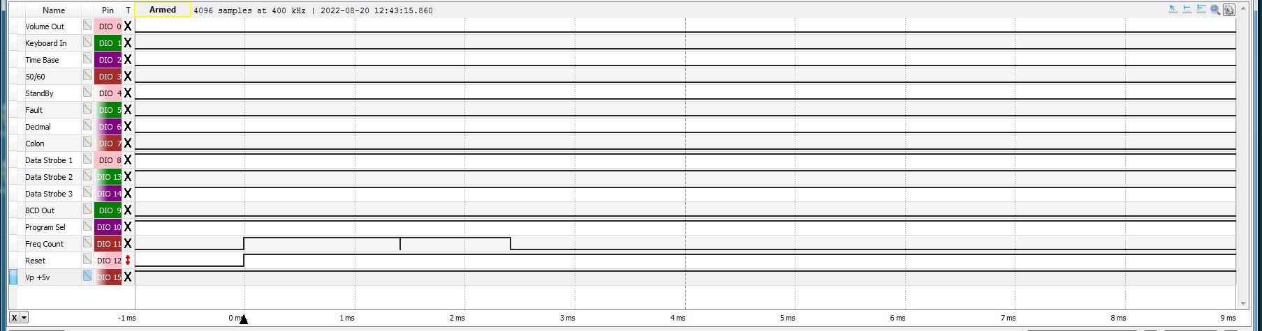
In the traces posted earlier, the reset signal is simply tied to the power signal. I know that this is not the ideal situation. I would have rather been able to generate a delayed signal that was triggered from the power signal, but I don’t think that it is possible with the test equipment that I’m using. If the RESET signal looks early, it is likely an anomaly related to how the test equipment scans or displays the signal.
I did a quick test by manually changing the reset signal (plugging in a jumper on the breadboard).

Except for the FreqCount signal, all of the signals usually remained unchanged. The FreqCount typically goes high for a random period of time, then returns to zero. I’m not sure what to surmise from this behavior.
I expected to see the outputs update as a group (of 8), but not all of the bits being the same value. For example, in the Data Strobe set of signals, I expected to see something other than 0 or 7 (all zeros or ones), which would indicate that the software was polling the keyboard or setting a particular LED display.
I don’t have any real experience with trying to debug a faulty CPU. Typically, at work, if a circuit/CPU was acting flaky, we trashed it and replaced it with a new one, or sent it back to the hardware group that likely did the same.
I didn’t expect my bench test to produce the behavior of a properly functioning CPU in a BM6000. It would be a very difficult to replicate the exact timing of all of the signals such that the diagnostics were happy. I did expect that the results from a given test would be fairly repeatable.
It seems like the CPU is running random assembly code. So far, it has not hit a HCF opcode, but it feels like it is just a matter of time ;-).
Glitch
21 August 2022 at 07:05 #36700artigBRONZE MemberSince there’s really nothing happening on the outputs after /Reset goes high it would seem that the program code is not running at all.
Sorry, I’m out of ideas for things to try.
27 August 2022 at 19:08 #36701GlitchBRONZE MemberI’m also out of ideas of what to try relative to the CPU. I’ve been able to test (most of) the rest of the receiver and aside from a few LEDs being dead, it still works pretty well. It has been a long time since I’ve listened to this piece of equipment. I forgot how nice it sounds, with a smooth, mellow quality that is hard to describe.
Can anyone comment on the availability of replacement CPUs?
My assumption is that they are generally unobtainable and the best bet is picking up a microprocessor board from a unit that is being parted out (that may or may not have a similar problem).
7 January 2023 at 20:24 #36702quattttroBRONZE MemberDid you ever figure out if the CPU was dead on your 6000? Mine exhibits the exact same symptoms, unfortunately.
7 January 2023 at 21:45 #36703GlitchBRONZE Memberquattttro: I think I was able to prove to myself that the CPU was indeed dead. I ended up swapping the bad CPU into another BM6000 and the main issue followed the CPU. I still have a mystery to solve since the original machine does not work properly with the “good CPU” from the other machine.
Have you checked the 5v-cpu and 5v voltages on Board 2? Have you replaced 2R89 and readjusted the RESET circuit?
Glitch
10 January 2023 at 05:17 #36704quattttroBRONZE Memberyes, 5v CPU (pin 39, iirc) and the other voltages are all exactly as noted in the service manual. I did try to adjust the reset circuit, but I get 0V across R92. I’m not really sure why that is.
-
AuthorPosts
- You must be logged in to reply to this topic.