Forum Replies Created
-
AuthorPosts
-
 MadskpGOLD Member
And BTW pin 5 is also ground so if you touch that while measuring you will probably also get 0V. Those small pins in these connectors are usually fididly to measure on
Location: Denmark
MadskpGOLD MemberDepending on how easy it is to see the pin numbers direction it could be that you are counting the pins from the wrong direction?
Counting to pin 4 from the wrong direction seems to be a ground pin which will read 0V

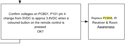
This test is only for checking if 5V drop to 3.8V, so I would expect a 5V reading.But the could be problems before in the chain. Try to look at page 3.4 in the servicemanual. There is a flowchart with things to test where this is only part of it.
The TV has to be connected to mains for the test, and all internal connections be intact, but as its part of a test for tv not turning on that should be it.
Location: Denmark
MadskpGOLD Memberbut the red lights are on the speakers as we speak, even though the MCL2AV box is not plugged in currently.
The speakers are active speakers with built in power supplies, so they will always be in standby indicated by the red light if they are plugged into mains even though there is no source.
Assuming they are wired to the main system in the living room and the MCL2AV box is just an addition to let you run them with the IR eye and remote for additional sound in another room.
I would assume that yes. That is the way his system was intended to be used, as a link room to the main system.
The IR eye, when the MCL2AV box is plugged in, does not come on, as the red light does not even light up.
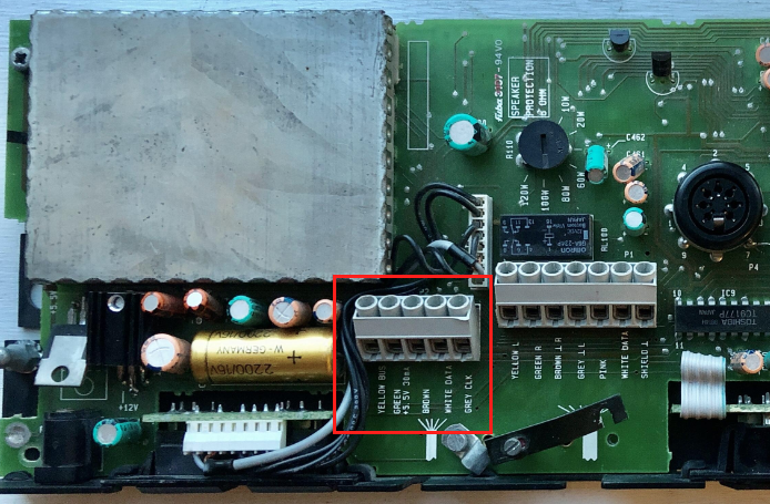
You could try to disconnect the IR eye from the screw terminal in the MCL2AV and try to measure the voltage at the screw terminal again. If it now shows 5V that would indicate that the problem is in the cable or the IR eye. If it is still 2V the fault is probably in the MCL2AV.
Also as Guy suggested you could try to connect the old IR eye again to see if that works
Maybe there’s something at the main system in the living room that I can reset or test to make sure there is accurate power going to the MCL2A box in the garage?
I don’t think that is nessecary at this point. The MCL2AV should work independently even though the main systems is disconnected. The MCL2AV do not use the 8V power from the main sytem as it has it’s own power suply.
Location: Denmark
MadskpGOLD MemberHello again. I have now re read the whole thread and I might have misunderstood which components are in your system.
If I understand it correctly you have the MCL2AV box in the garage, and the IR eye + speakers in the bed room?
The measurement of the 2V where did you take that at the splice?
If sio you could instead try to measure it at the screw terminals in the MCL2AV box to see if it has the correct voltage of 5V.
I should be done between the terminals for the green and the brown wire

Hope this helps
Location: Denmark
MadskpGOLD Member1- By another board you mean within the video engine board or another one?
It was the video engine board I meant, but the connection could pass to other boards. Best thing to do might be to make the measurement i refered to from the servicemanual in my earlier post.
This is the back part I missed attaching it. Is that component that has “H CM . &” a capacitor?
Hmmm I can’t really tell what type of component that is, and wheether the black is burnt or just how it is supposed to look. It tried to do a Google picture search on it, but with no relevant result.
Location: Denmark
MadskpGOLD MemberAnd I might have to revisit my Ouverture to see if I can get it fully working. Maybe one of the caps I put in it have slipped the board
Location: Denmark
MadskpGOLD MemberAnd guess what? I put it back together and it works, and for more than 20 minutes this time!! It is a Good Friday!
Nice to hear that it did the trick, and the soldering time was not wasted 🙂
and potentially do the other jobs (belts, adjustment of display brightness and battery replacement).
I can only recommend doing the belts while it’s open based on both my Ouverture and some other things I have worked on
Location: Denmark
MadskpGOLD MemberSo I connected the ethernet cable to it and I was able to turn it on via the b&o app, but there is no picture, I managed to play the radio and it works fine but all I see is black screen. And it still doesn’t respond to the remote.
Ok so the TV is not totally dead. Thats a positive.
Would this issue be on the T-CON board or video engine board ?( even tho it is functioning without image) and the remote not working can be a related or a side effect from the video engine as the IR sensor is attached to it?
Not really sure, but the fact that the IR board connects to the video engine makes it possible that it can be a fault on another board then the IR.
I took some close ups of the boards. the back light one seems like there is some leaking around some parts (brown one and the big black piece) I noticed it today.
I would not suspect these components to be leaking. To me it looks more like solder residue.
I havent checked voltages yet, I need to learn how to do that.
If you have a multimeter set it to measuring DC voltage and measure between the point mentioned in the service manual (provided you can locate it) and a ground point. Ask if you need more advice.
Also on the room awareness module, there a dark spot on the side of a white thing, is that an indicator that it was blown or something?
It could be something. I can’t locate it on you pictures. Could you make a close up photo of that component?
There are other B&O products where IR problems are related to failing capacitor.
Other than that I don’t see any electrolytic caps on your picture of the IR board, so unless there are some on the other side of it this should not be the issue.
Location: Denmark
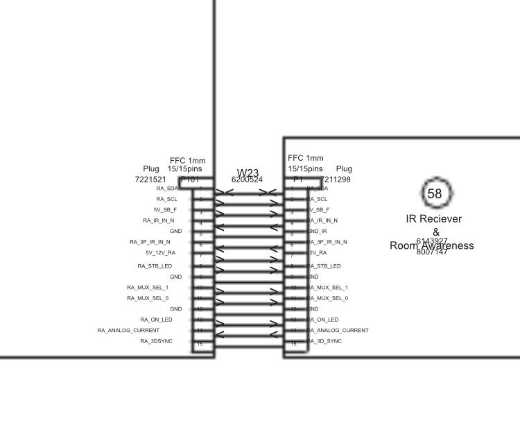
MadskpGOLD MemberYou could also try this thing mentioned in the service manual to confirm whether it is PCB 58

Location: Denmark
MadskpGOLD MemberI had that component replaced and it still doesn’t turn on.
Too bad that did not work, although it might have need to be replaced anyway based on the condition it was in.
Ive been studying the service manual and it could be that the “IR Receiver & Room Awareness” ( 58Module 8007282 PCB58) need to be replaced
Interesting. There are other B&O products where IR problems are related to failing capacitor. Maybe there are capacitors on PCB58 that need to be replaced. Could yo try to take this PCB out and take some photos of it?
I wonder if the cable that connects to it might be damaged (photo) anyone know what kind/name this cable is?
It is a Ribbon cable. It is probably custom made for this particular TV. If it indeed is damaged an alternative solution could be to desolder the connectors on the boards and solder another flat cable to the solder pads in both ends. This will of course make it harder to disconnect the separate boards, but should not be to often that is nessecary.
Location: Denmark
MadskpGOLD MemberJust chiming in here with my 2 cents and a couple of questions
- You do mention a Beosstem 4500, but I can not tell from your description if you have been using that through any of the xtra speaker kits? The reason for asking this is that the MCL2AV shown in you picture can work independently of the MCL system when you are only using it’s local input connectors as it have it’s own powers supply. Therefor it can work without the MCL cabling and the Beosystem 4500 for the use case you have describe.
- You do mention that there is also xtra speaker kits in the garage and the bedroom. Are these the same type as the one in your picture? The reason for asking is that there is both an xtra speaker kit (where the grey box is an MCL2A) and en xtra active speaker (where the grey box is an MCL2AV as the one in your picture) and there are quite some differences in them.
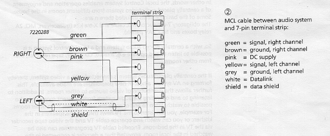
- Where have you measure the 2V you are mentioning? The MCL cable do supply a voltage of arround 8V in the pink vire from the main system (in your case the Beosystem 4500). The voltage can be measure between the pink and the brown wire. Some voltage drop should be expected along the cable, but 2 V seems low.
Here is the cable colors.

Do note that it is also important the the two speaker connectors are connected correctly on the Beosystem 4500. Left and right must no be switched as one of them caries voltage and the other data signals.
Also important that they are conencted to the speaker 2 terminal on the Beosystem 4500 as the speaker 1 connctors do not supply voltage for the MCL system.
If you have MCL2A boxes (Those without local inpus) these can only work if they get power from the Beosystem 4500.
Hope that these inputs can help you further. You are welcome to ask if any doubts
Location: Denmark
MadskpGOLD MemberProbably gonna be more of an addition than addiction
I have never really been found of the look of it, but when BS4 was announced at a price I couldn’t say no to I picked it up anyway
Of course it’s sticky all over since B&O at that point was going all in with these coatings on all surfaces.
Furthermore when powered up the glass door is moving down, but when it reach the buttom gear noice starts and keeps going.
Could be a sensor problem?

I was very surprised by the low weight of it when I picked it up. B&O must really have saved on the material bill on these units.
Anyway. First things first. I have allready started to remove the sticky coating as my fingers get all black when I touch it
Location: Denmark
MadskpGOLD MemberI think it was this thread Stoobie was refering to
https://forum.beoworld.org/forums/topic/beo4-special-remote/
Location: Denmark
25 March 2024 at 05:33 in reply to: ML/NL converter used with only ML products, just to give access to Beo APP #53801MadskpGOLD MemberThis thread may answer some of your questions
https://forum.beoworld.org/forums/topic/beo-converter-controls-beocenter-9500/Location: Denmark
MadskpGOLD MemberThanks for the information: by adjusting the timing between the two presses of “menu” I could indeed get into the test menu. 00 then showed “sw: 2.0”.
Great to hear although it did not solve your problem.
If you end up looking for another BL3500 with the correct software the best chance might be a MK2, although they came with software 3.0 or 3.1 initially so no garantee for the correct SW version
Location: Denmark
MadskpGOLD MemberWhen I press Menu it activates the timer with display “On 0:00”.
Ok that would indicate that you need to press Menu once more to get the timer away. Else the numbers are going into the timer settings.
I have tried this many times probably because I was pressing Menu Menu to fast in a row, so try to adjust the timing between the key presses
the document with the MLGW compatibility is attached. You can find it on the site https://mlgw.bang-olufsen.dk/source/documents/
Thanks a lot. Very usefull. I have nvewer looked at info for the ML gateway, so thats why I did not have that info
Location: Denmark
MadskpGOLD MemberIt is in a working setup with BS5 as audiomaster and a beolink converter NL/ML as videomaster to get access to my Beovision Avant 55 MKI. All commands seem to work properly.
Then it sound odd that the Menu 0 0 Go command does not work.
How about Menu 0 2 Go (shows status of Masterlink)?
I removed it from the wall and the type plate shows sw: 2.0 Type No:1601.
When it was delivered with SW 2.0 it is most probable a MK1 version. To verify that further you can see if MCL is engraved in the metal beneath the 8 Pin DIN connector on the back. You can also check the serial number MK1 has serial numbers lower than 19343452
If you did not buy the BL3500 from new there is of course a slight chance that a former owner updated the software, but the only wa to confirm is the Menu 0 0 Go command
And BTW since it’s most likely a MK1 the key sequence is only with one press on Menu.
I would like to reroute the light commands from my BL3500 to my Beolink Gateway which is only working from sw version 3.3.
Can you tell where you have the info regarding the Light commands and software version from? Reason for asking is that in another thread https://forum.beoworld.org/forums/topic/bl3500-and-the-mcl-pl-connector/page/3/#post-22047 I am trying to keep a list of software changes in the BL3500 and would like to get as much info as possible, and with sources if possible.
Thanks in advance
Location: Denmark
MadskpGOLD MemberI tried to find out the sw version of my BL3500 (from 1994) but neither combination (“Menu Menu 00 go” or “Menu 00 go” worked. Any idea what can cause this? Kind regards, Luc
Is the BL3500 in a working setup and/or does it react to other remote commands?
Location: Denmark
MadskpGOLD MemberI still have to take the video engine board out to see if there is corrosion, from the top it looks fine. I found the capacitor on ebay, https://www.ebay.ie/itm/292412377560 just €8. I will update you guys if that fixes it. Thanks for all the help!
Nice. Looking forward to your findings. Would be great if replacing this could make these great TV’sluve a little longer
Location: Denmark
MadskpGOLD MemberBtw do you see any corrosion on other components arround this capacitor on the board?
Hopefully it did not damage other things than itselfLocation: Denmark
-
AuthorPosts