


Home › Forums › Product Discussion & Questions › BeoPlay › Beoplay V1 not turning on
Tagged: Beoplay V1
- This topic has 48 replies, 8 voices, and was last updated 2 weeks, 5 days ago by
 slm@skals.dk.
-
AuthorPosts
-
27 February 2024 at 01:32 #53042
 MadskpGOLD Member
A friend of mine have a Beoplay V1 40″ that will no lunger turn on
When he is plugging the TV into an outlet the LED will blink green for a short while, but no reaction to remote commands at all.
I have guided him through the proces of changing the option settings in case it should have ended up in option 0 for some reason. This however did not do any difference, and the TV does not give the red blink when the option is set.
A google search doesn’t give much, but I have seen a single mention of a leaking battery
Searching for Beovision 11 problems I see one mentioning of a blown capacitor
Both things sounds like plausible causes.
Does anyone have anymore information regarding this or any experience in fixing it?
I have a special interest in this as I also have a V1 myself, and would like to do some preventive measures on that if possible.
Location: Denmark
27 February 2024 at 17:32 #53043Does it show up in the B&O app or in the Beotool app (assumed it is online)?
The leaking battery issue is probably more common than one might think.
I know that in Denmark any serious dealer will replace the battery before selling a V1.
All you can hope for is, that it has not already caused too much damage.
I’d let a dealer or a skilled technician have a look, if it was mine.MM
Location: Flensborg————Danmark
27 February 2024 at 19:42 #53044MadskpGOLD MemberDoes it show up in the B&O app or in the Beotool app (assumed it is online)?
No unfortnuatly ha has not configured the V1 in the app before this happened
The leaking battery issue is probably more common than one might think. I know that in Denmark any serious dealer will replace the battery before selling a V1. All you can hope for is, that it has not already caused too much damage. I’d let a dealer or a skilled technician have a look, if it was mine.
Do you know if the leaking battery can cause issues like this?
Also, do you have any idea if the battery is placed in the power supply or the Video engine PCB?
Location: Denmark
27 February 2024 at 22:08 #53045I have a faulty V1-32 that I bought with a similar fault with similar LED behaviour. I saw reference to a leaking battery somewhere on the forum so I opened up the TV and searched the PCBs inside, and found nothing remotely like a battery! I think my internal investigations damaged something else because now I get no lights whatsoever. It’s now back in a box waiting for donor parts, or to become a donor!
EDIT: Mine didn’t show up in the app either (when connected to my network via RJ45).
Location: Warwickshire, UK
My B&O Icons:
 28 February 2024 at 11:23 #53046MadskpGOLD Member
so I opened up the TV and searched the PCBs inside, and found nothing remotely like a battery!
A pitty. It could be nice to know where this battery is placed, and if it could be DIY replaced.
Worst case if it is like some batteries used on 30 year old computeres, the PCB traces could be destroyed by the battery acid.
Location: Denmark
29 February 2024 at 14:22 #53047MadskpGOLD Memberso I opened up the TV and searched the PCBs inside
How did you approach the opening of the TV?
The reason for asking is that the disassembly instructions mentions insertion of protection sheets, and I wonder if that is of a specific material or if it could just be a piece of paper or cardboard?

I guess the purpose is to avoid scratches on the painted surfaces
Location: Denmark
1 March 2024 at 08:32 #53048
When I first opened mine it was screen downwards on an old cot mattress. I re-inserted the top part of the bracket so it could pivot (unfold) upwards.
I then reversed the tv so that the back was downwards and the screen carefully pivoted up.
Location: Warwickshire, UK
My B&O Icons:
1 March 2024 at 08:37 #53049I can only assume that those sheets would protect from scratches caused by opening the plastic ‘hinge’ beyond its normal range of movement.
Location: Warwickshire, UK
My B&O Icons:
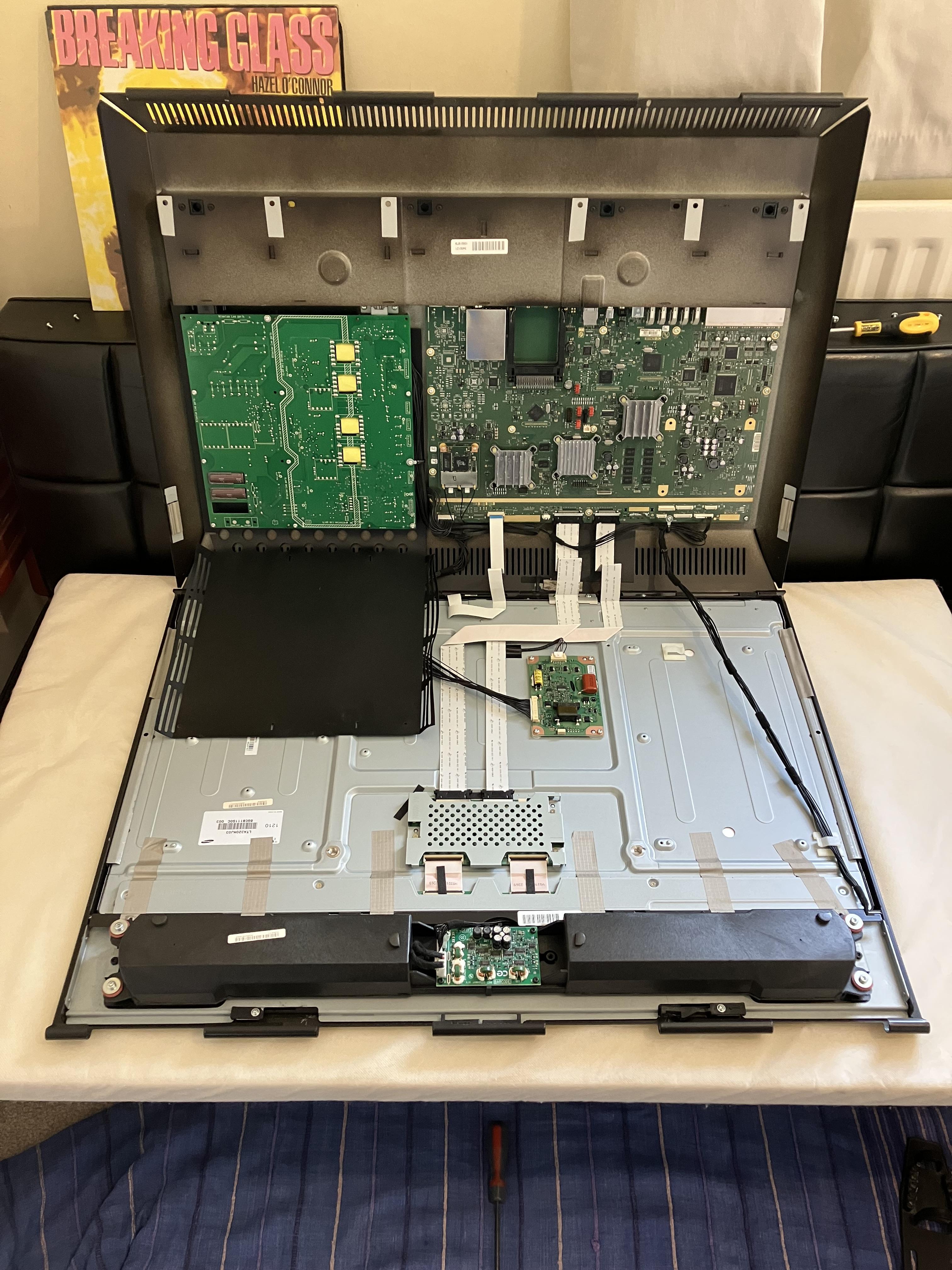
1 March 2024 at 09:30 #53050MadskpGOLD MemberWhen I first opened mine it was screen downwards on an old cot mattress. I re-inserted the top part of the bracket so it could pivot (unfold) upwards. I then reversed the tv so that the back was downwards and the screen carefully pivoted up.
Thanks. Thats a very helpfull view of TV opened up. I do not spot a battery here either, but could of course (why place it so it is easy to get to) be placed on the other side of the PCB. My best guess would be that it is placed on the large mainboard as the function is probably to keep data when the TV has no power.
Other possible culprits could also be capacitors on the PSU board. Your photo shows two large ones placed in openings in the PSU board.
I can only assume that those sheets would protect from scratches caused by opening the plastic ‘hinge’ beyond its normal range of movement.
Maybe it is more nessecary if the TV is opened up 180 degress. I guess that B&O’s description of it is to be 100% sure that a service technitian do not make scratches when he is working on it.
Location: Denmark
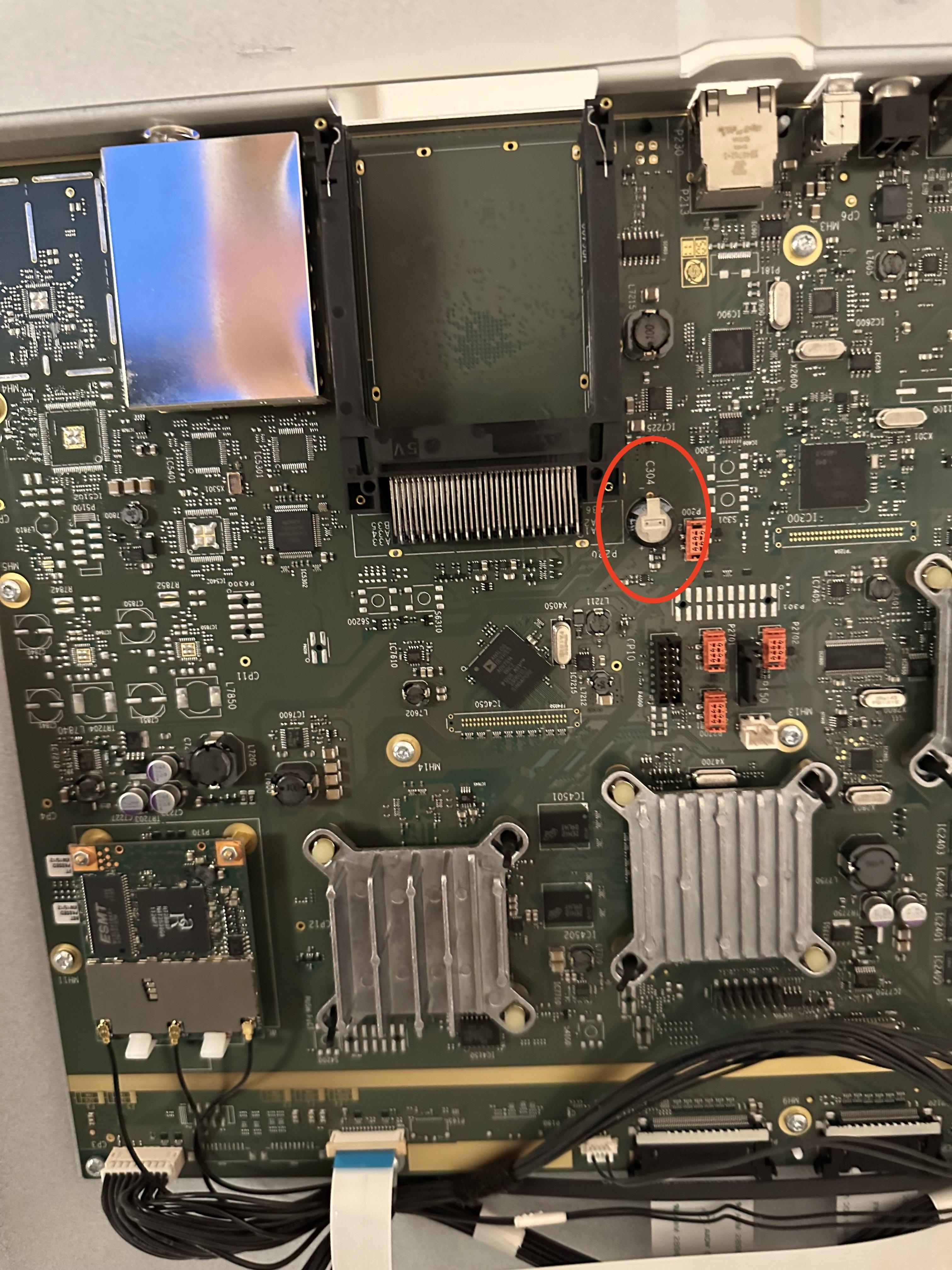
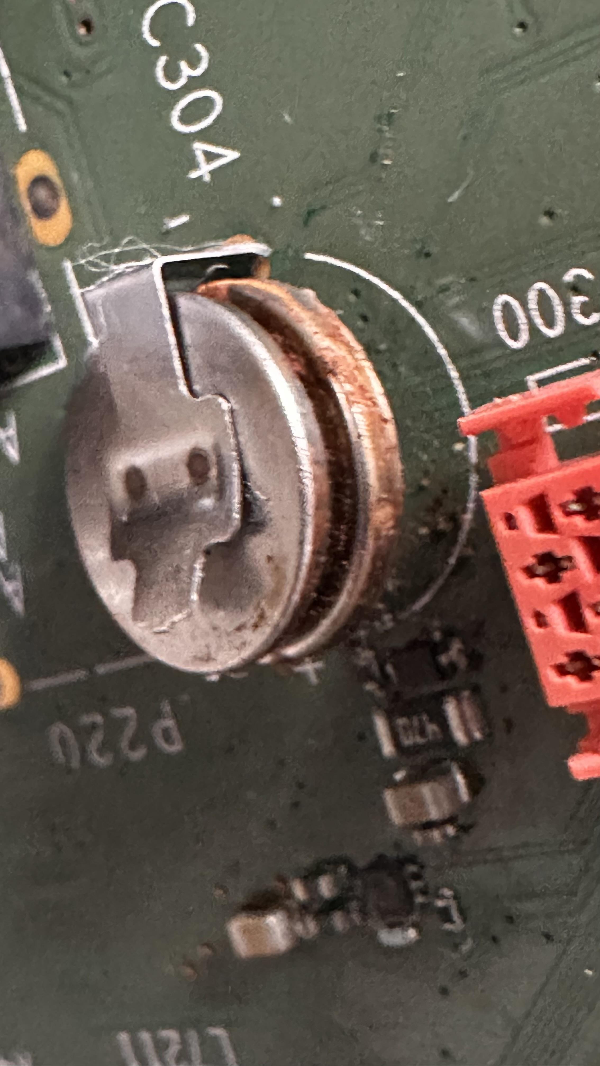
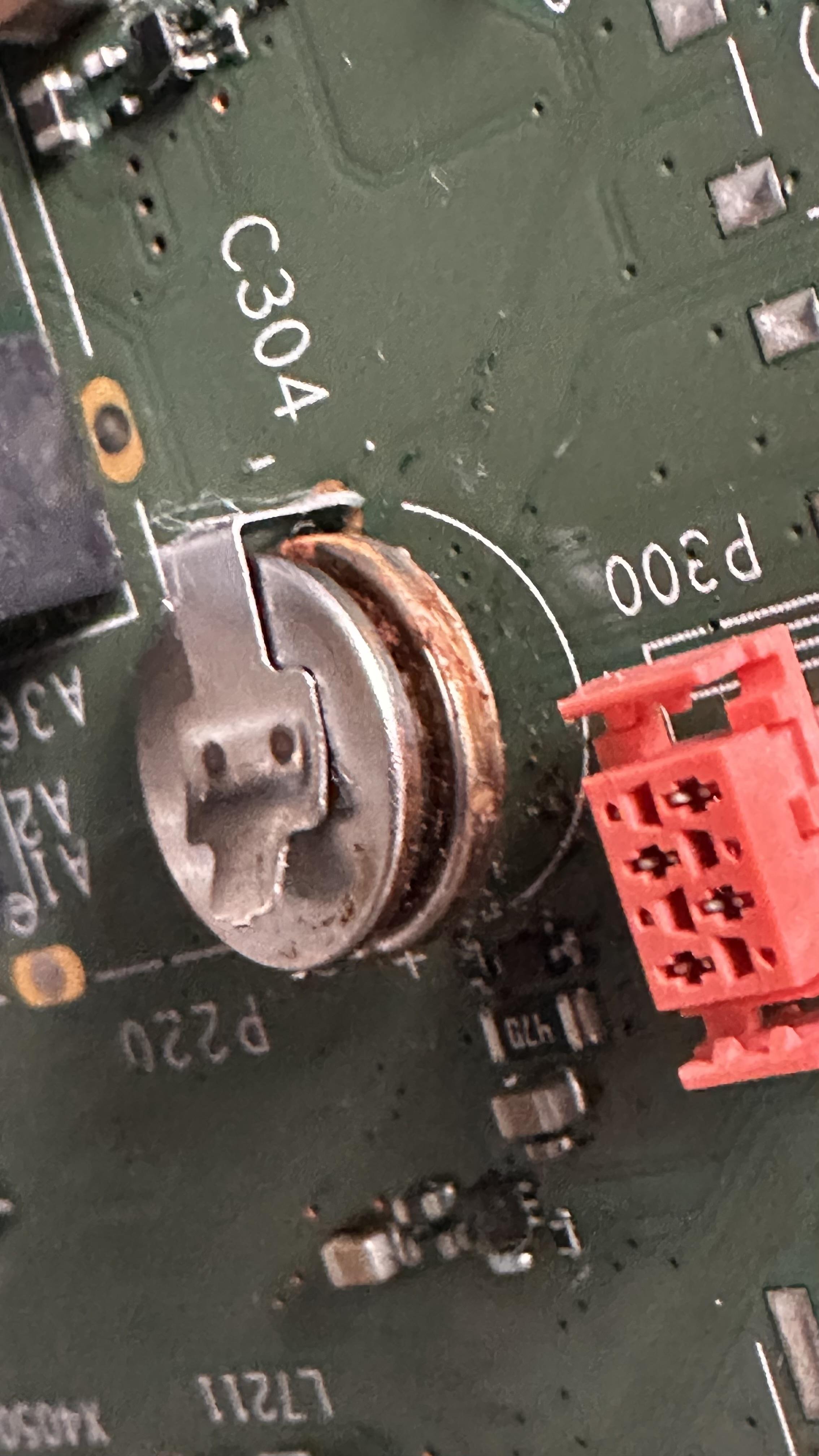
2 March 2024 at 18:41 #53051MadskpGOLD MemberMy friend opened up his V1 today and sent me some pictures from the inside.
Although the mainboard look a lot like the one in Guy’s V1 I not spot a component that could be a battery although the marking C304 suggest a capacitor.
And from a slightly angled view
There are no visible leaks from this component, but that of course does not men that it couldn’t be defect.
Any thoughts
Location: Denmark
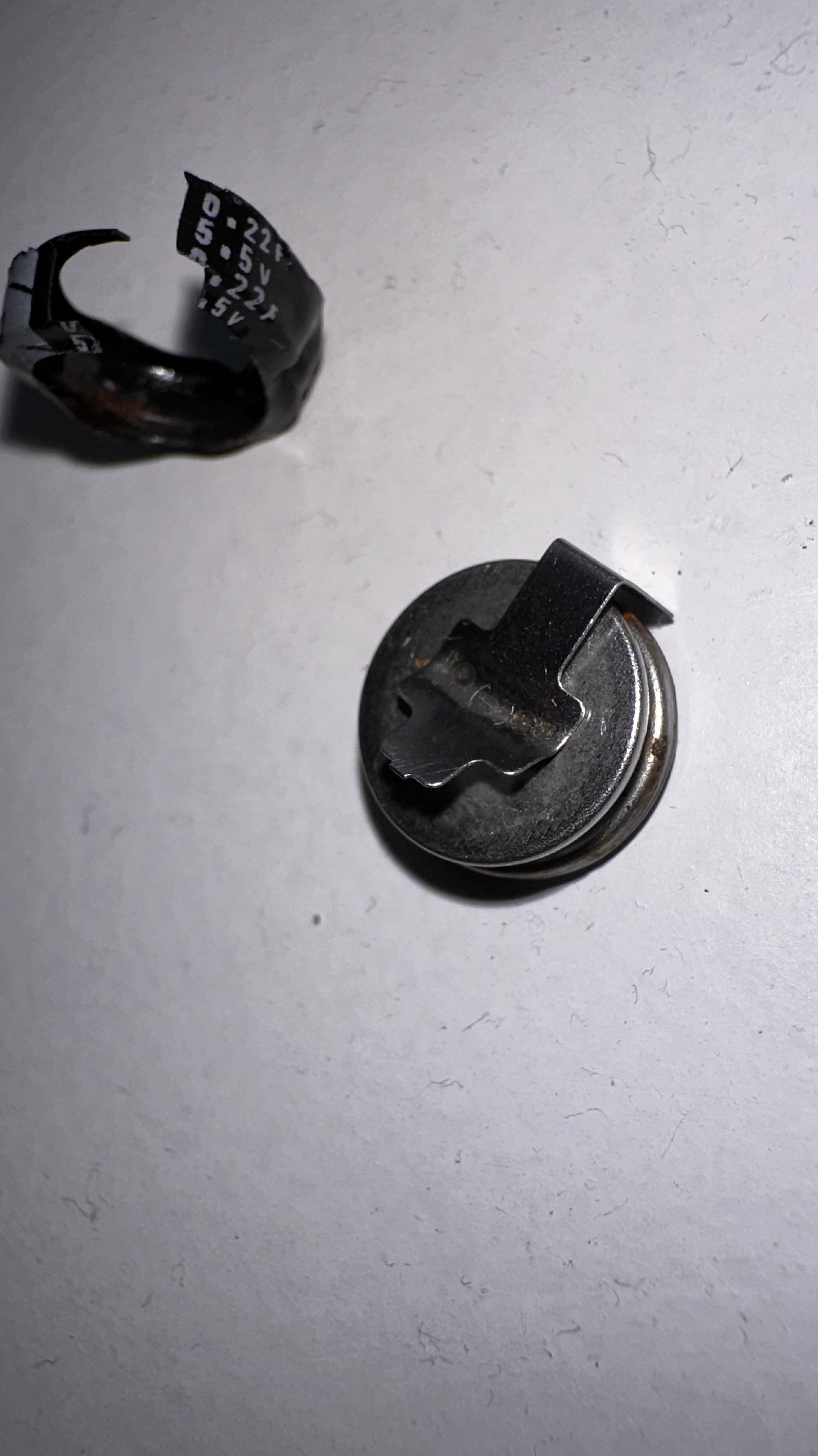
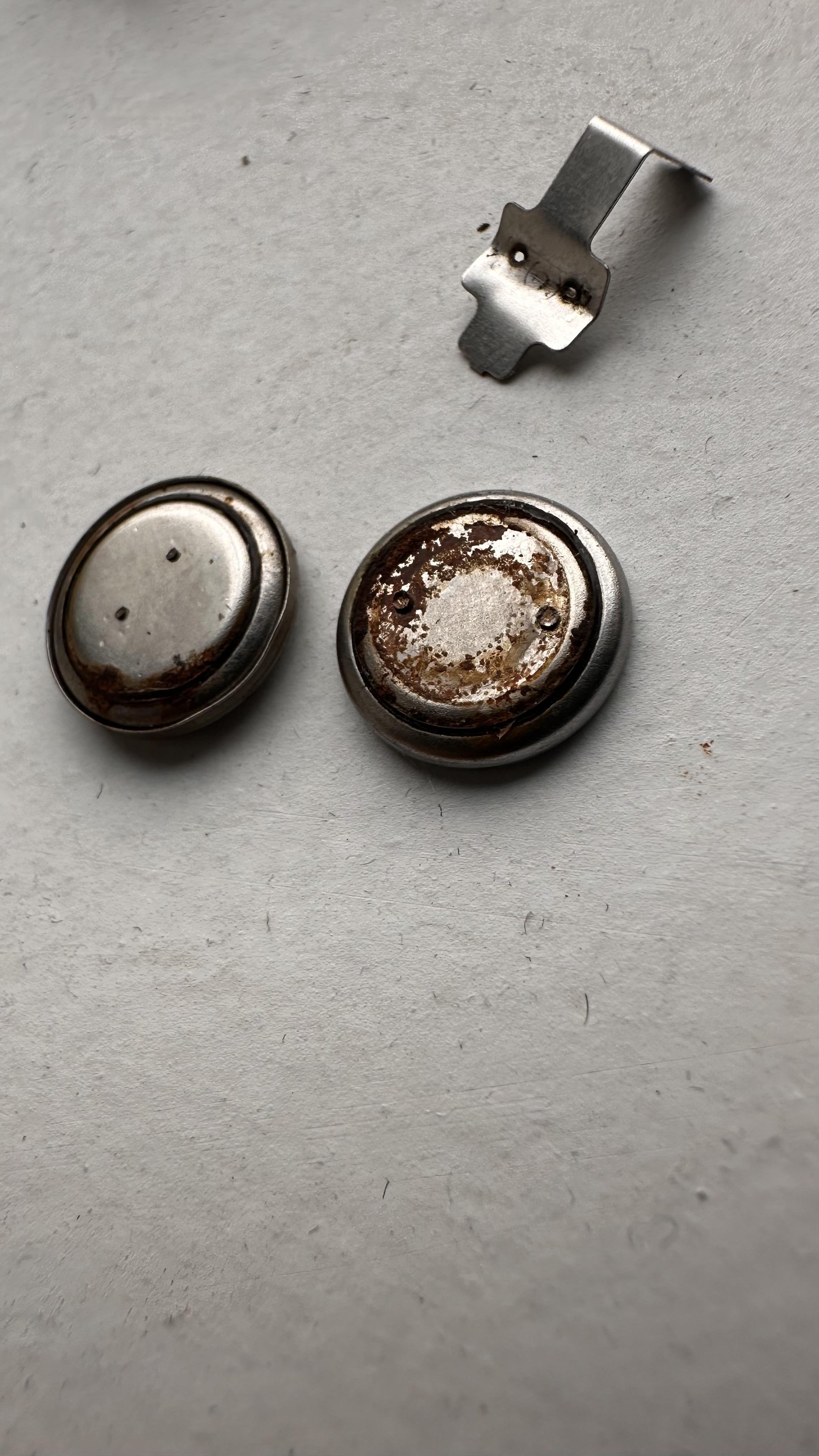
21 March 2024 at 14:45 #53052alexsallesBRONZE MemberIm having the same issue with my V1. I noticed there are some voltage written on black thin plastic label around it. and suddenly that come apart and they look like two batteries.
I tried to remove the soldering that was holding the clip and I ended up getting the whole clip off the board.
Anyone has an idea how to remove the clip from the battery and which kind of battery will fit here? they dont seem to have anything written on it apart from some voltage and amperage on the plastic label.
is it two batteries or the lower one is is the actual battery and the top part is a holder that got rusted on it and made them too stuck together?
 21 March 2024 at 15:43 #53053alexsallesBRONZE Member
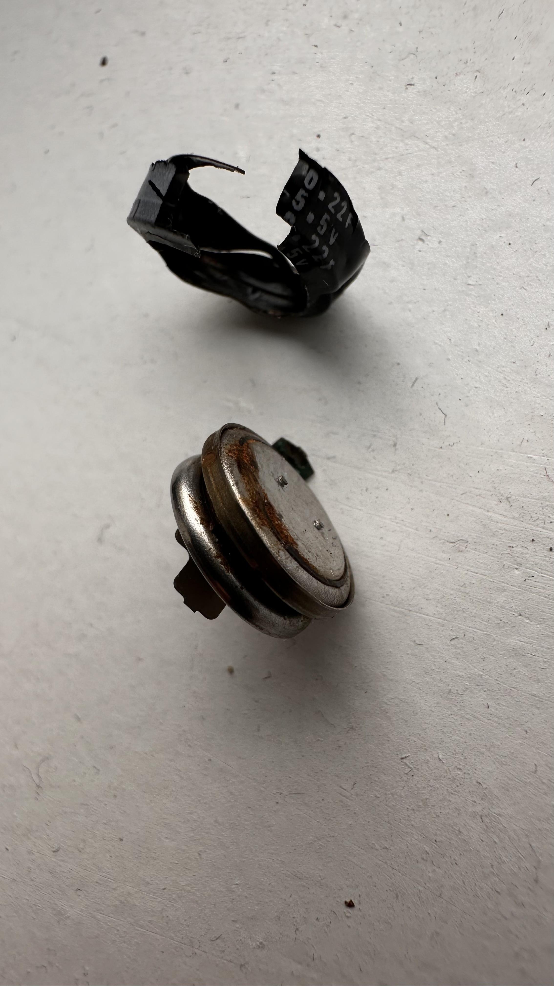
I took them apart they seem like batteries, I wonder which kind, any ideas?
21 March 2024 at 16:15 #53054MadskpGOLD MemberBased on the markings on the plastic 0.22uf 5.5V ina Google search it is not a battery but a super- / backup capacitor.
It seems to be widely available and at a fair price
Very interesting if replacing it actually solves the problem. The on you have seems fairly corroded indeed
Location: Denmark
21 March 2024 at 16:44 #53055MadskpGOLD MemberBtw do you see any corrosion on other components arround this capacitor on the board?
Hopefully it did not damage other things than itselfLocation: Denmark
22 March 2024 at 12:33 #53056alexsallesBRONZE MemberI still have to take the video engine board out to see if there is corrosion, from the top it looks fine.
I found the capacitor on ebay, https://www.ebay.ie/itm/292412377560 just €8.
I will update you guys if that fixes it. Thanks for all the help!
22 March 2024 at 12:58 #53057MadskpGOLD MemberI still have to take the video engine board out to see if there is corrosion, from the top it looks fine. I found the capacitor on ebay, https://www.ebay.ie/itm/292412377560 just €8. I will update you guys if that fixes it. Thanks for all the help!
Nice. Looking forward to your findings. Would be great if replacing this could make these great TV’sluve a little longer
Location: Denmark
28 March 2024 at 17:23 #53058alexsallesBRONZE MemberI had that component replaced and it still doesn’t turn on.
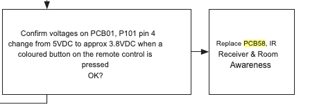
Ive been studying the service manual and it could be that the “IR Receiver & Room Awareness” ( 58Module 8007282 PCB58) need to be replaced. My light turns green for a while which they say on the manual the TV is ready to be used.
Like it doesn’t react to my remote at all and I tried other B&O remotes I have working on other tvs and it doesn’t turn on. I’ve been looking for that module part online and so far no luck. I wonder if the cable that connects to it might be damaged (photo) anyone know what kind/name this cable is?
28 March 2024 at 18:58 #53059MadskpGOLD MemberI had that component replaced and it still doesn’t turn on.
Too bad that did not work, although it might have need to be replaced anyway based on the condition it was in.
Ive been studying the service manual and it could be that the “IR Receiver & Room Awareness” ( 58Module 8007282 PCB58) need to be replaced
Interesting. There are other B&O products where IR problems are related to failing capacitor. Maybe there are capacitors on PCB58 that need to be replaced. Could yo try to take this PCB out and take some photos of it?
I wonder if the cable that connects to it might be damaged (photo) anyone know what kind/name this cable is?
It is a Ribbon cable. It is probably custom made for this particular TV. If it indeed is damaged an alternative solution could be to desolder the connectors on the boards and solder another flat cable to the solder pads in both ends. This will of course make it harder to disconnect the separate boards, but should not be to often that is nessecary.
Location: Denmark
28 March 2024 at 19:03 #53060MadskpGOLD MemberYou could also try this thing mentioned in the service manual to confirm whether it is PCB 58

Location: Denmark
29 March 2024 at 12:57 #53061alexsallesBRONZE MemberThanks @Madakp for the help.
So I connected the ethernet cable to it and I was able to turn it on via the b&o app, but there is no picture, I managed to play the radio and it works fine but all I see is black screen. And it still doesn’t respond to the remote.
Would this issue be on the T-CON board or video engine board ?( even tho it is functioning without image) and the remote not working can be a related or a side effect from the video engine as the IR sensor is attached to it?
I took some close ups of the boards. the back light one seems like there is some leaking around some parts (brown one and the big black piece) I noticed it today.
I havent checked voltages yet, I need to learn how to do that.
Also on the room awareness module, there a dark spot on the side of a white thing, is that an indicator that it was blown or something?
-
AuthorPosts


- You must be logged in to reply to this topic.