


Home › Forums › Product Discussion & Questions › BeoPlay › Beoplay V1 not turning on
Tagged: Beoplay V1
- This topic has 48 replies, 8 voices, and was last updated 2 weeks ago by
 slm@skals.dk.
-
AuthorPosts
-
29 March 2024 at 13:47 #53062
 MadskpGOLD Member
So I connected the ethernet cable to it and I was able to turn it on via the b&o app, but there is no picture, I managed to play the radio and it works fine but all I see is black screen. And it still doesn’t respond to the remote.
Ok so the TV is not totally dead. Thats a positive.
Would this issue be on the T-CON board or video engine board ?( even tho it is functioning without image) and the remote not working can be a related or a side effect from the video engine as the IR sensor is attached to it?
Not really sure, but the fact that the IR board connects to the video engine makes it possible that it can be a fault on another board then the IR.
I took some close ups of the boards. the back light one seems like there is some leaking around some parts (brown one and the big black piece) I noticed it today.
I would not suspect these components to be leaking. To me it looks more like solder residue.
I havent checked voltages yet, I need to learn how to do that.
If you have a multimeter set it to measuring DC voltage and measure between the point mentioned in the service manual (provided you can locate it) and a ground point. Ask if you need more advice.
Also on the room awareness module, there a dark spot on the side of a white thing, is that an indicator that it was blown or something?
It could be something. I can’t locate it on you pictures. Could you make a close up photo of that component?
There are other B&O products where IR problems are related to failing capacitor.
Other than that I don’t see any electrolytic caps on your picture of the IR board, so unless there are some on the other side of it this should not be the issue.
Location: Denmark
29 March 2024 at 14:17 #53063alexsallesBRONZE MemberWould this issue be on the T-CON board or video engine board ?( even tho it is functioning without image) and the remote not working can be a related or a side effect from the video engine as the IR sensor is attached to it?
Not really sure, but the fact that the IR board connects to the video engine makes it possible that it can be a fault on another board then the IR.
1- By another board you mean within the video engine board or another one?
Also on the room awareness module, there a dark spot on the side of a white thing, is that an indicator that it was blown or something?
It could be something. I can’t locate it on you pictures. Could you make a close up photo of that component?
This is the back part I missed attaching it. Is that component that has “H CM . &” a capacitor?
29 March 2024 at 18:58 #53064MadskpGOLD Member1- By another board you mean within the video engine board or another one?
It was the video engine board I meant, but the connection could pass to other boards. Best thing to do might be to make the measurement i refered to from the servicemanual in my earlier post.
This is the back part I missed attaching it. Is that component that has “H CM . &” a capacitor?
Hmmm I can’t really tell what type of component that is, and wheether the black is burnt or just how it is supposed to look. It tried to do a Google picture search on it, but with no relevant result.
Location: Denmark
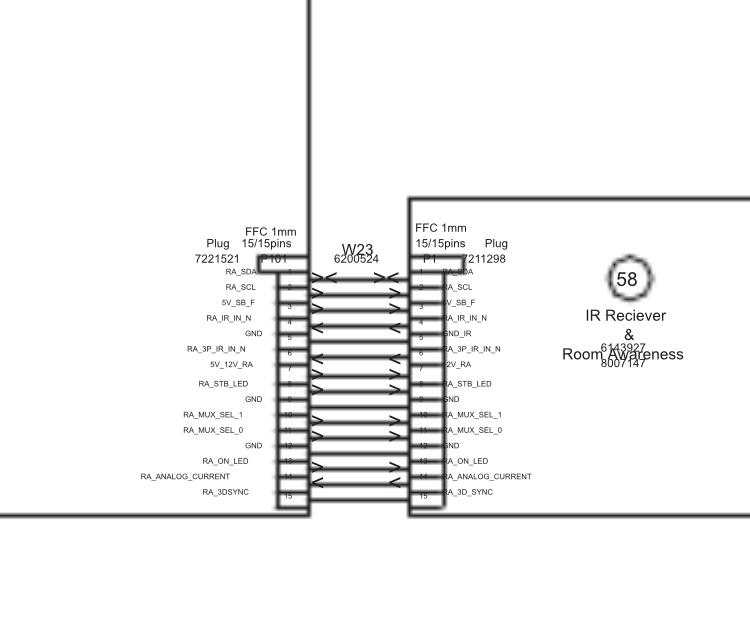
31 March 2024 at 02:17 #53065alexsallesBRONZE MemberSo I measured it with the multimeter on DC on a screws on the board and on metal parts for ground on that pin number 4 on the P101. and the numbers are most of the time on close to zero it doesn’t seem to react to the remote at all.
just with the multimeter if the remote awareness was working by the time i touch the pin 4 it should be giving 5V and then go down to approx. 3.8v, correct when the colored buttons on the remote are pressed, right? not changing any value on the screen by touching or pushing the buttons on the remote means this awareness board is dead and probably the culprit?
The tv doesn’t need to be on, right? i didn’t turn it on for that test.
Thanks again Madskp
31 March 2024 at 08:36 #53066MadskpGOLD MemberDepending on how easy it is to see the pin numbers direction it could be that you are counting the pins from the wrong direction?
Counting to pin 4 from the wrong direction seems to be a ground pin which will read 0V

This test is only for checking if 5V drop to 3.8V, so I would expect a 5V reading.But the could be problems before in the chain. Try to look at page 3.4 in the servicemanual. There is a flowchart with things to test where this is only part of it.
The TV has to be connected to mains for the test, and all internal connections be intact, but as its part of a test for tv not turning on that should be it.
Location: Denmark
31 March 2024 at 08:39 #53067MadskpGOLD MemberAnd BTW pin 5 is also ground so if you touch that while measuring you will probably also get 0V. Those small pins in these connectors are usually fididly to measure on
Location: Denmark
31 March 2024 at 17:24 #53068alexsallesBRONZE MemberThe pin position was correct but then I tried with the mains plugged in and when I touched the pin with the multimeter something on the awareness board blew up. It still shows 5volts but now nothing changes as i screwed it up.
I dont l know for sure if I accidentally touched between the pins and it cause that but now I know for sure that awareness board is gone hahaha even smoke came from it. I found a board on ebay now 110euros with shipping.
at this point I dont even know if it’s worth fixing this tv. Was the problem something else on the video engine and now that I made that part blow up would it affect the video engine in case it was okay and the problem was really the awareness one?
31 March 2024 at 17:51 #53069MadskpGOLD MemberI tried with the mains plugged in and when I touched the pin with the multimeter something on the awareness board blew up
Sorry to hear that. Can you tell which component that blew up based on your pictures?
at this point I dont even know if it’s worth fixing this tv. Was the problem something else on the video engine and now that I made that part blow up would it affect the video engine in case it was okay and the problem was really the awareness one?
Hard to tell, but at least when you get the new PCB you will know if that was it or if it is the video engine part
Location: Denmark
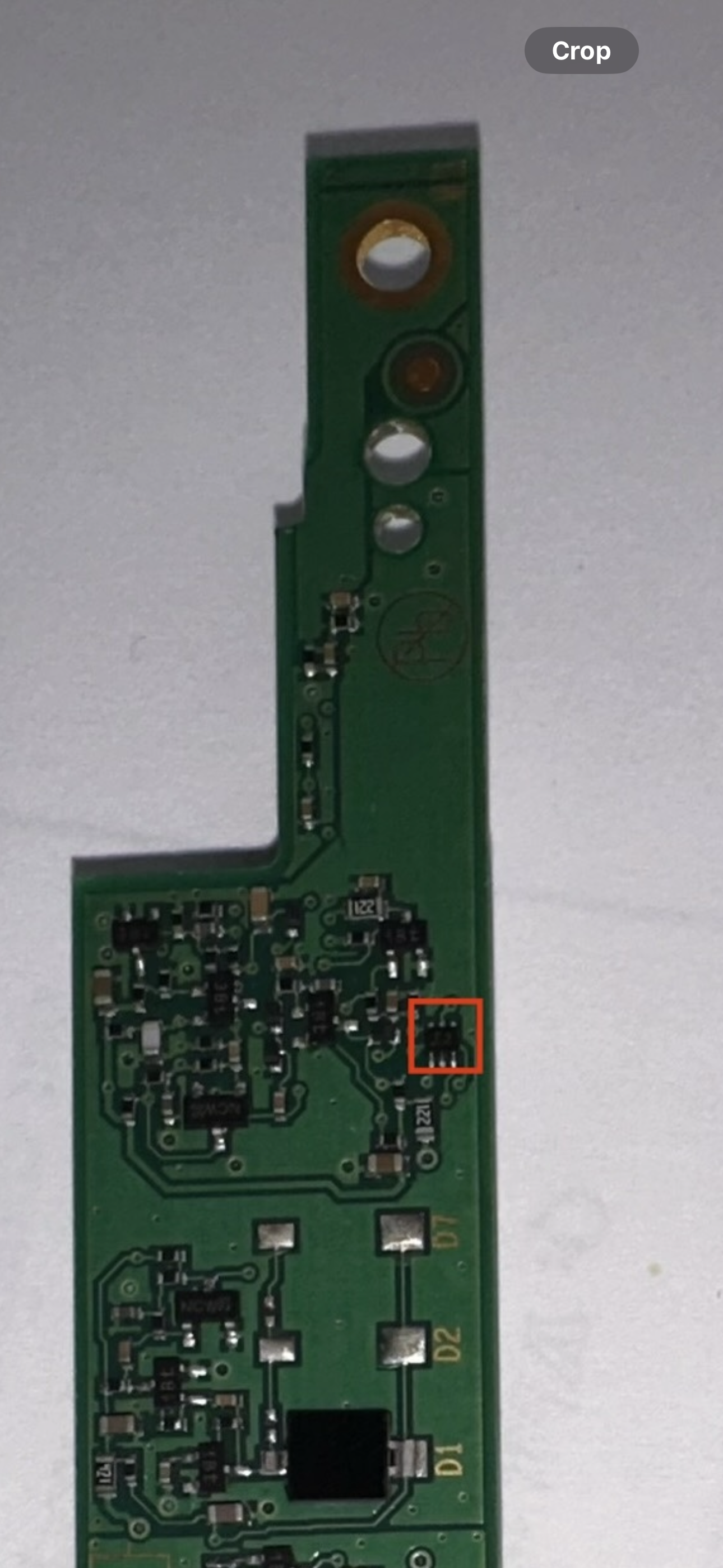
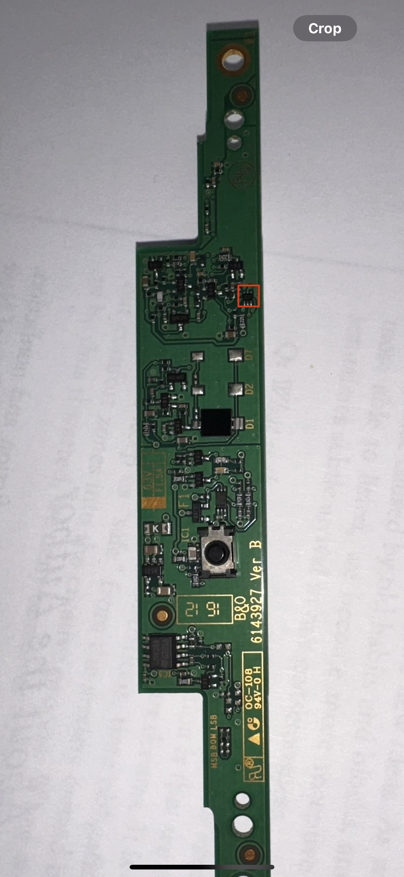
31 March 2024 at 18:51 #53070alexsallesBRONZE Member
I think it was this part I highlighted in red square. I have to take the black cover off to see for sure if it is only this component.
Fair, I’ll buy it and see how it goes. It’s the easier way to find out the origin of the issue. I’ll let know you the outcome after I install the new PCB58.
Thank you very much for your thorough help and advice! I would be lost without you.
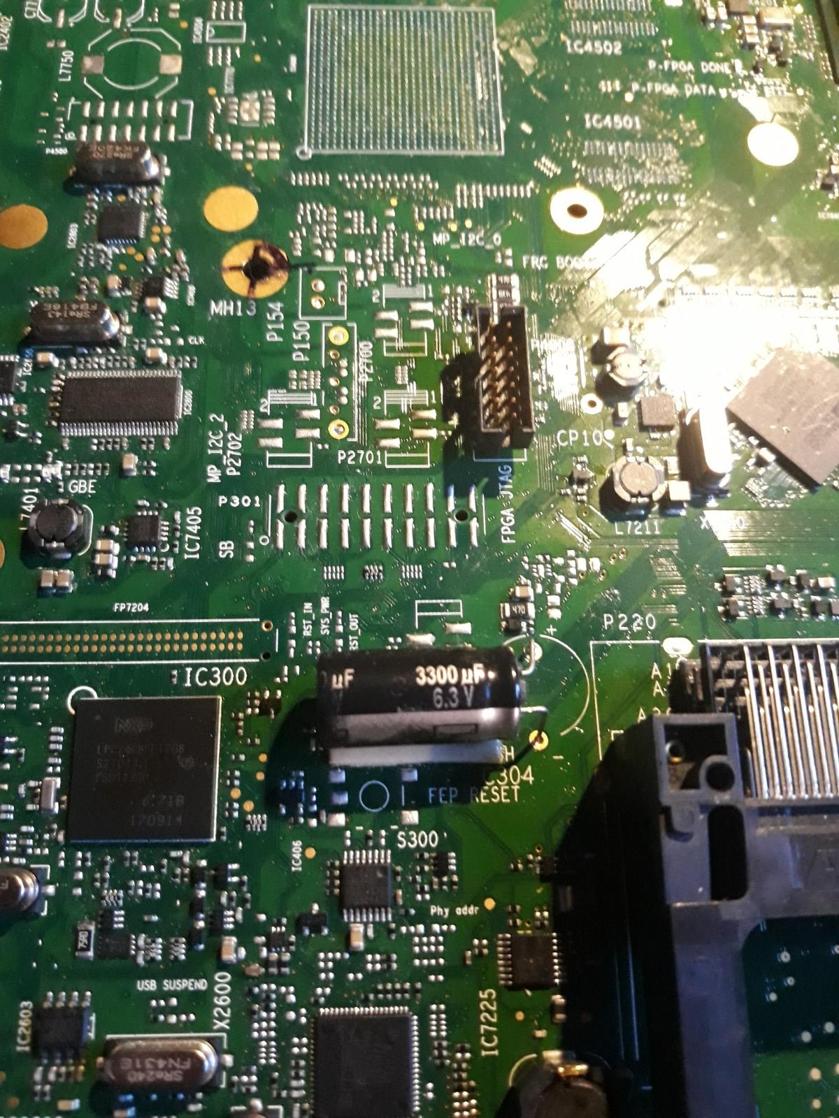
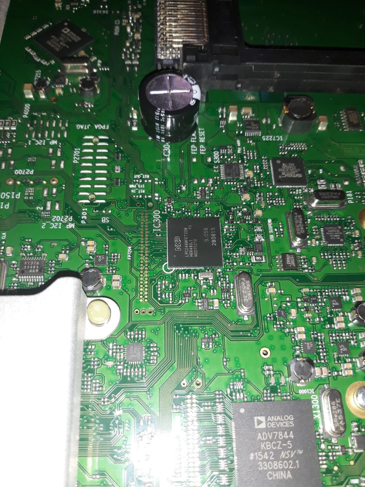
31 March 2024 at 20:30 #53071Hello, in my case the electrolyte from the damaged supercapacitor damaged the PCB paths that ran under it. I could barely solder them.
One of them is the signal from the IR module to the FEP IC300 processor.13 May 2024 at 05:23 #55568MadskpGOLD MemberOn jacek1313 saidHello, in my case the electrolyte from the damaged supercapacitor damaged the PCB paths that ran under it. I could barely solder them.
One of them is the signal from the IR module to the FEP IC300 processor.Thanks for chiming in with this very relevant info. This info suddenly makes it very clear why a leaking backup capacitor can make the IR function of the TV not work.
Also based on the corrosion we have seen on the pictures of the super capacitor earlier in this thread it sounds very belivable that this could leak down on the PCB.
Would you happen to have any pictures of the damage and/or your repair of the PCB?
Location: Denmark
13 May 2024 at 10:24 #55574jacek1313BRONZE MemberI don’t have any photos. I cleaned the PCB under the capacitor to bare copper, soldered the paths with thin wires and covered them with PVB varnish.
13 May 2024 at 15:14 #55578MadskpGOLD MemberOn jacek1313 saidI don’t have any photos. I cleaned the PCB under the capacitor to bare copper, soldered the paths with thin wires and covered them with PVB varnish.
Thanks for clarifying. And great that there might be a relativly easy fix (depending on ones skills of trace repair). Maybe by studying the PCB layout it is possible to find some spots that could be connected by a wire instead of the PCB repair.
But this new info tells me that it might be easier to replace the super capacitor before it leaks to prevent PCB damage.
Location: Denmark
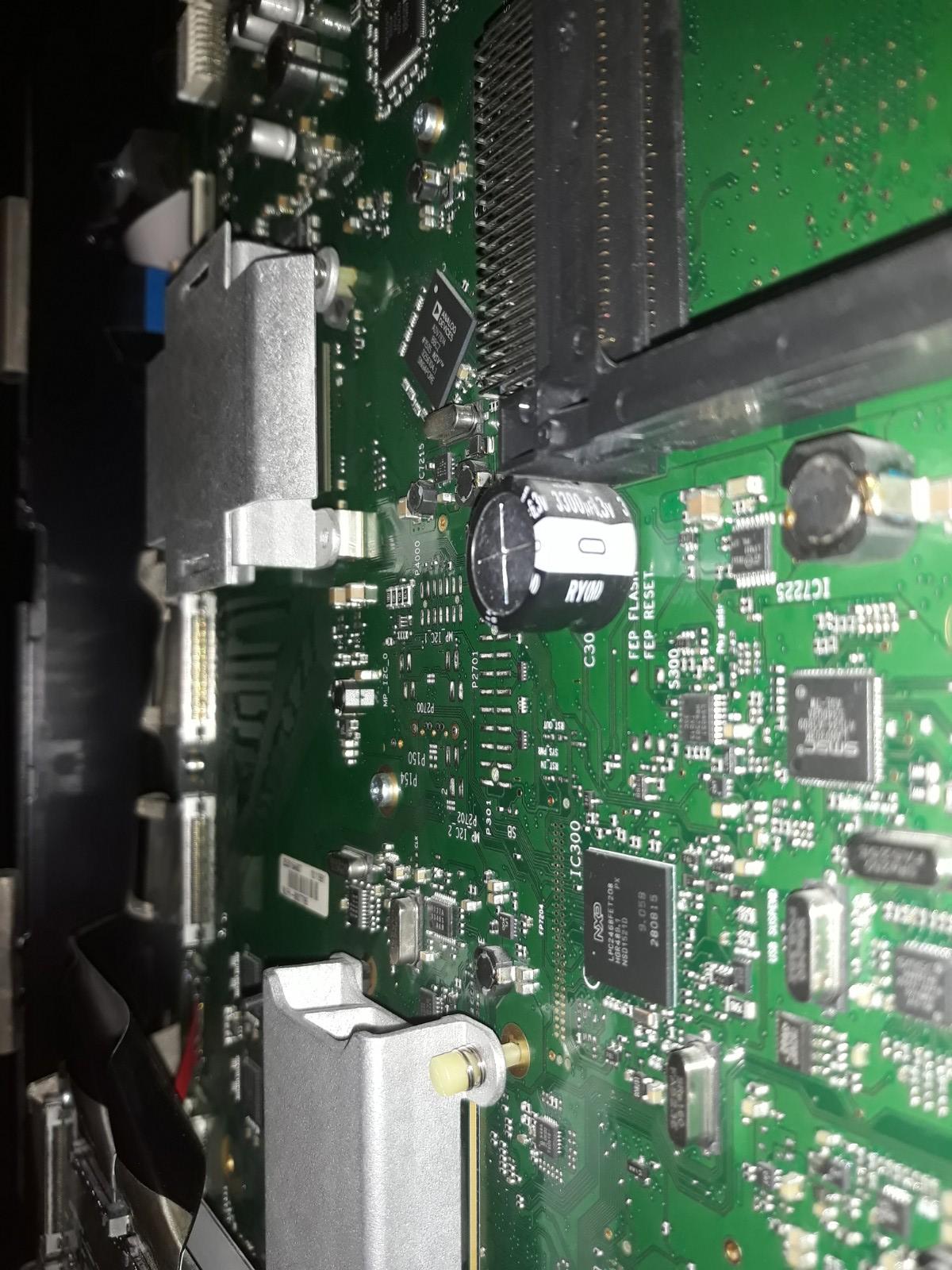
13 May 2024 at 15:59 #55580jacek1313BRONZE MemberBeoSystem 4 boards already use a 3300uF capacitor.
 13 May 2024 at 18:05 #55581MadskpGOLD MemberOn jacek1313 said
BeoSystem 4 boards already use a 3300uF capacitor.
Just to be sure, was this mounted by you or do you think it was mounted from the factory?
I am not sure how the 3300uF capacitor can replace a 0.22F super capacitor, but maybe someone can enlighten me?
Location: Denmark
13 May 2024 at 23:13 #55584jacek1313BRONZE MemberThis is the original capacitor from Beosystem 4.
13 May 2024 at 23:21 #55586jacek1313BRONZE MemberThese are photos from Avant 75.
14 May 2024 at 08:16 #55591MadskpGOLD MemberOk very interesting that both the Avant and the Beosystem 4 has a 3300uF electrolytic capacitor instead of the 0.22F super capacitor.
I can see that Beoplay V1 is from 2012, Beosystem 4 from 2013 and Beovision Avant from 2014, so it makes sense that a component is changed in newer product lines. Wheether it is because the super capacitor was causing trouble already at that time or if it was just a cost cutting measure is a good question.
But thanks for the pictures
Location: Denmark
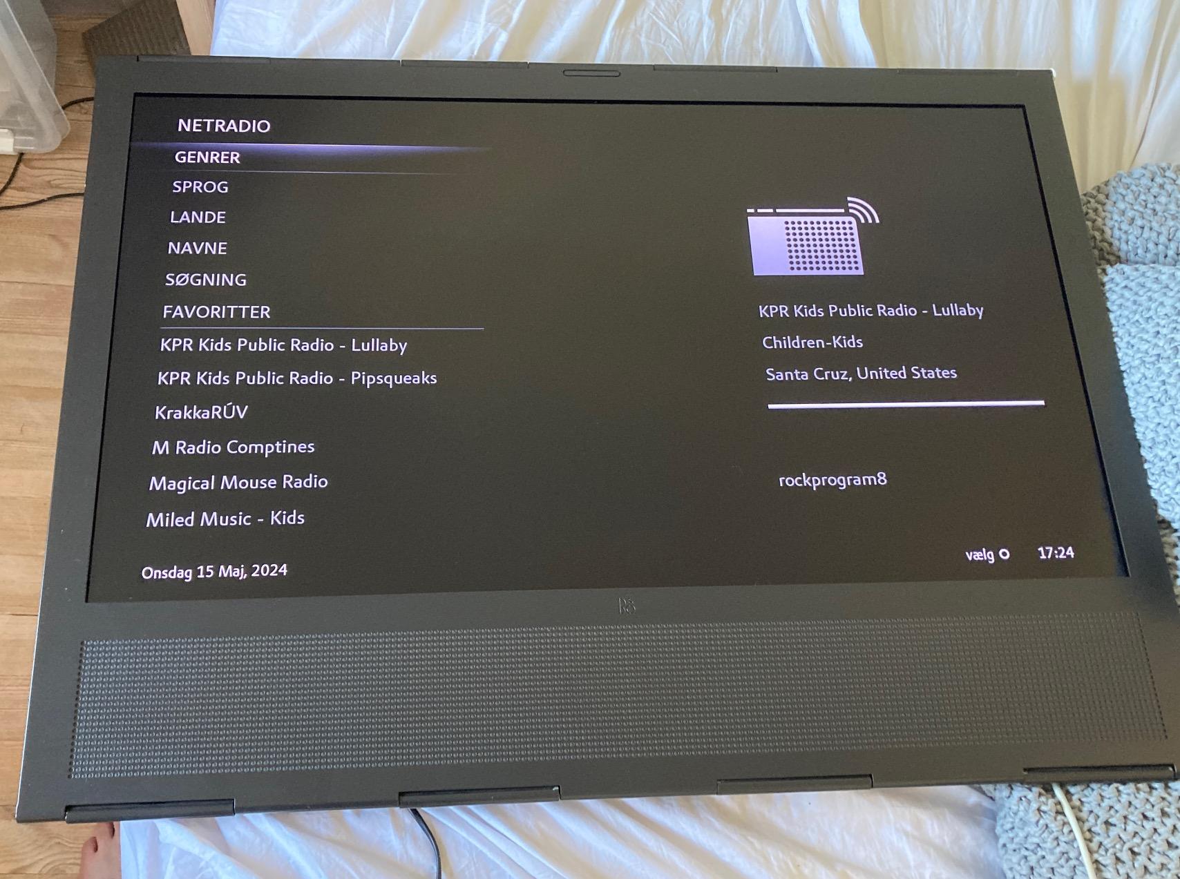
15 May 2024 at 19:39 #55660MadskpGOLD MemberGiven that we might have the solution for this issue I took the plunge and bought a relativly cheap V1 announced as non working with the symptom not reacting to the remote, and the green dioade ligtning up when connected to power.
Fantastic enough when I got this home and connected it to power and my home network via the ethernet connection I was able to find it with the B&O app, turn it on with picture, and controlling everything with the app. No reaction to remote control though as expected.

Location: Denmark
-
AuthorPosts
- You must be logged in to reply to this topic.