Forum Replies Created
-
AuthorPosts
-
25 October 2022 at 15:55 in reply to: BeoLab 8000: 5-pin cable from RCA-PCB to LED-PCB sensitive #39852
 BRONZE Member
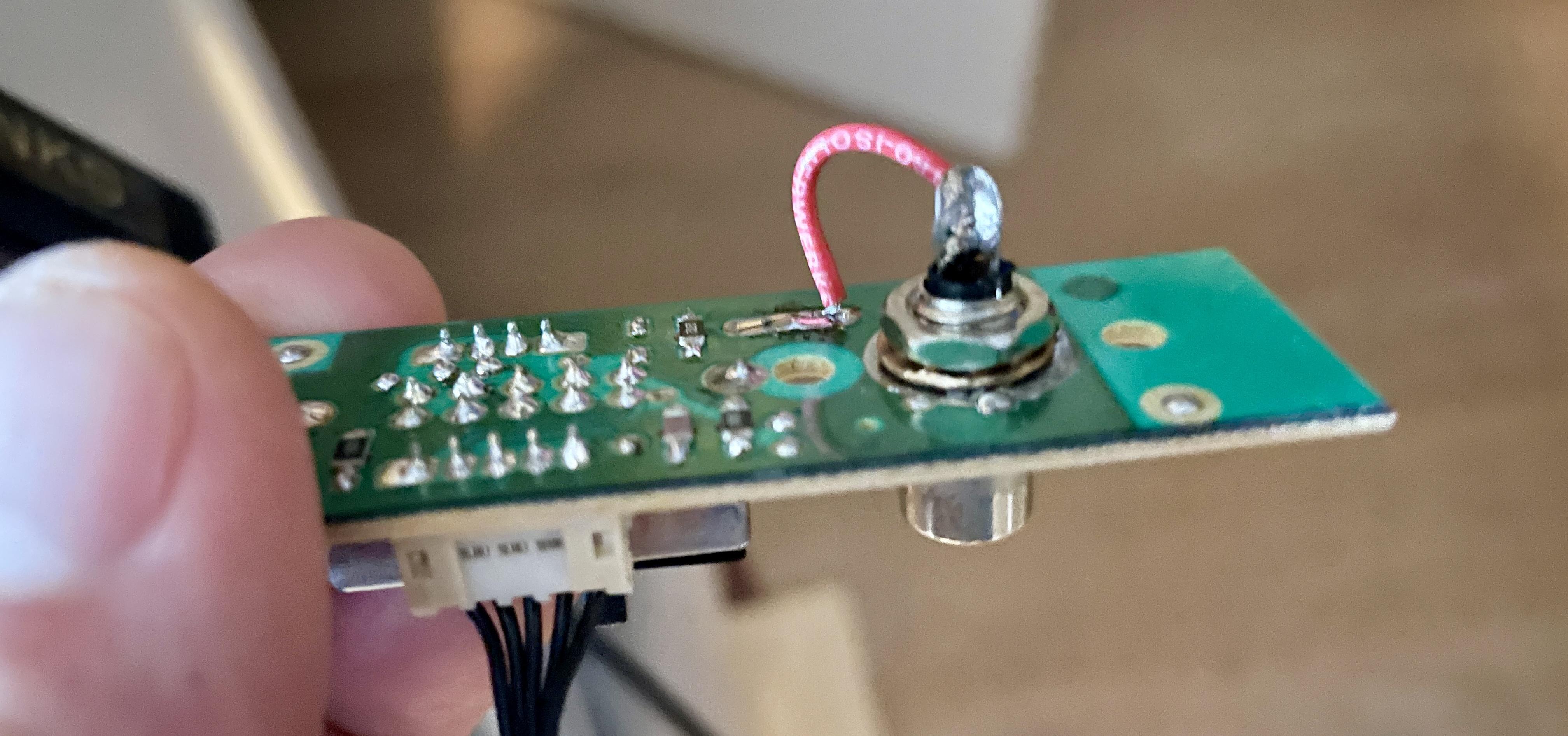
@Die_Bogener: As you suggedted, I connected a shorted RCA plug to the RCA connector on PCB05. Result: the hum is gone, Auto stand-by switches to OFF and stays OFF, and when touching the P4 cable, Auto stand-by does not switch on.
So this does look good! But now I need to make a next step, because I need the RCA connections, so I cannot keep them shorted.
Here’s some additional things I changed, tested and the results.
Checks 2
I took another look at PCB05: used a dentist tool to scratch along the edges of the RCA GND contact on the PCB, and at some other connections/traces on the PCB. Just to be sure, there’s no traces that make unwanted contact.
Tested after checks 2
- Input switch set to RCA: When the BeoLab was switched on again, the hum was more or less gone. The Auto stand-by does switch to OFF, but after one second immediately switches ON again, and then repeatedly goes ON – OFF – ON – OFF.
- Input switch set to PL: Auto stand-by switches OFF, and stays OFF > OK. Touching the PCB, P3 / 4 cables, etc. has no influence on Auto stand-by, it stays OFF > OK.
Checks 3
Extra checks on the GND and disturbances of the RCA plug on PCB05.
Tests with Checks 3
All checks done with the input selector set to RCA.
- Connected a wire between GND of the RCA connector outside shell above the PCB, and the GND underneath the PCB. Problem remains > No positive result.
- Put a metal cap over the RCA plug for shielding. Problem remains > No positive result.
- Connected my old iPhone with a ‘mini-jack-to-RCA’ cable to the RCA socket on PCB05 > No hum, Auto stand-by switches to OFF and stays OFF.
- In situation 3. I also touched the cable of P4 on PCB05. When touching it, Auto stand-by switches to ON. When releasing the P4 cable, Auto stand-by switches OFF again and remains OFF.
What bothers me is, that the Auto stand-by actually works well, but …
Touching the P4 cable makes the Auto stand-by switch ON again. Therefor, it is not yet working reliably.
Questions
- What do you conclude from this?
- What next step do you suggest?
Location: The Netherlands
Favourite Product: BeoSound 9000
My B&O Icons:
 23 October 2022 at 06:42 in reply to: BeoLab 8000: 5-pin cable from RCA-PCB to LED-PCB sensitive #39850
Thnx BeoTool!
In my case the RCA connector is not soldered to the PCB. It is fixed to the board by a nut, and I have tightened the nut well. So it must be another cause.
Any idea?

Location: The Netherlands
Favourite Product: BeoSound 9000
My B&O Icons:
22 October 2022 at 16:21 in reply to: BeoLab 8000: 5-pin cable from RCA-PCB to LED-PCB sensitive #39848Findings
First I disconnected and took PCB05 and PCB06 out of the speaker. Checked again for foam rot rests. Did some extra cleaning to be sure. Then I made following checks and did resoldering.

Checks
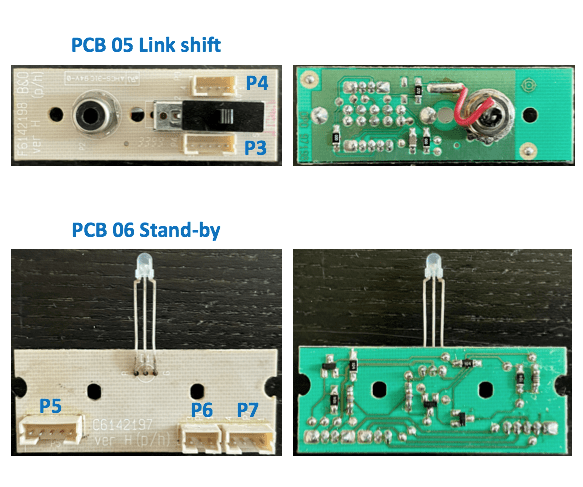
PCB 05 – Link shift (in outside foot)- Continuity: measured continuity on all traces and solder points connected > OK.
- Re-soldering: re-soldered all solder points, incl. connectors and component pins > Done.
PCB 06 – Stand-by (in bottom speaker casing)
- Continuity: measured continuity on all traces and solder points connected > OK
- Re-soldering: re-soldered all solder points, incl. connectors and component pins > Done.
P4 Connector (between PCB05 & PCB06)
- Continuity: measured continuity on all 5 pins of the cable > OK.
Next
After this I put the BeoLab back in original configuration: PCB06 screwed back in normal position, PCB05 connected but hanging loose. iPhone connected (as audio source) via external mini-jack to RCA cable, connected to RCA in foot. Result: There is a little hum, but Auto stand-by does switch OFF.
Findings:
- When the P3 connector or cable is touched, Auto stand-by switches ON. But when let loose, it also quickly switches OFF.
- When the P4 cable is touched, nothing happens.
- When the P6 connector (audio cable) on PCB05 (Link shift) is touched, Auto stand-by also switches to ON. But also, quickly switches OFF when let go. This also happens when the connector of this same cable on the amplifier side is being touched.
Question
There still is sensitivity in the audio signal path.
What is the best next step I could make?Location: The Netherlands
Favourite Product: BeoSound 9000
My B&O Icons:
16 October 2022 at 17:43 in reply to: BeoLab 8000: 5-pin cable from RCA-PCB to LED-PCB sensitive #39847Thanks! I will make those checks and come with my findings.
Location: The Netherlands
Favourite Product: BeoSound 9000
My B&O Icons:
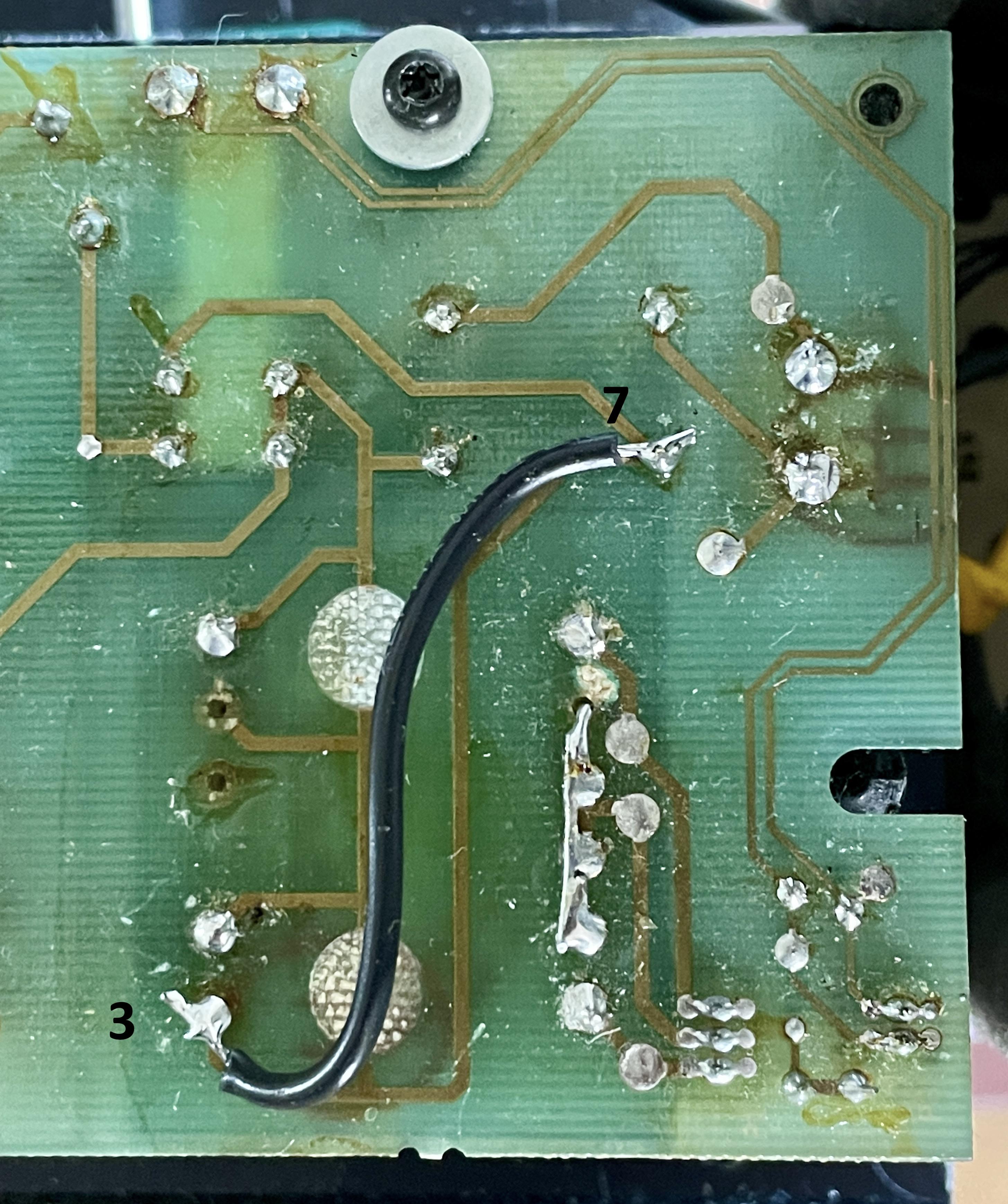
To make this thread complete, here’s a picture of the by-pass wire correcting the broken trace.

Location: The Netherlands
Favourite Product: BeoSound 9000
My B&O Icons:
After having made the by-pass wire for the T2 transformer and concluding it worked properly again …
I today put the PSU/AMP block back in the speaker casing, and connected the speaker panel. So back to the original configuration.
Having done some tests, and using the system for a few hours; it’s properly alive again!
Special thanks to: Beobuddy, Dillen and Die Bogener!
Location: The Netherlands
Favourite Product: BeoSound 9000
My B&O Icons:
Thanks for your response Tignum, great info again!
Yes, I will do some reburbishment with Akustikstoff in the near future. I have several BeoLab 8000 grills with terribly looking cloth; wrinkles, holes, discolored, ect.
I do like the looks of Akustikstoff standard black, so that’s what it is gonna be. And I am sure it will look better than the original.
Location: The Netherlands
Favourite Product: BeoSound 9000
My B&O Icons:
Update, after adding a wire between 7 + 3.
I added the wire and made a first check powering the system. Result:
- I immediately heard the relay clicking.
- The power LED became alive again; turned green and back to red.
Next I measured AC voltage on T2:
- Between 4 + 6 = 43 volts AC
- Between 4 + 5 = 22 volts AC
- Between 5 + 6 = 22 volts AC
Are these the correct measurements?
Location: The Netherlands
Favourite Product: BeoSound 9000
My B&O Icons:
Thnx BeoBuddy.
So, you measure from 7 along the trace to point 3 where the trace is broken.
- Yes, confirm. From 7 to 3 there is no continuity.
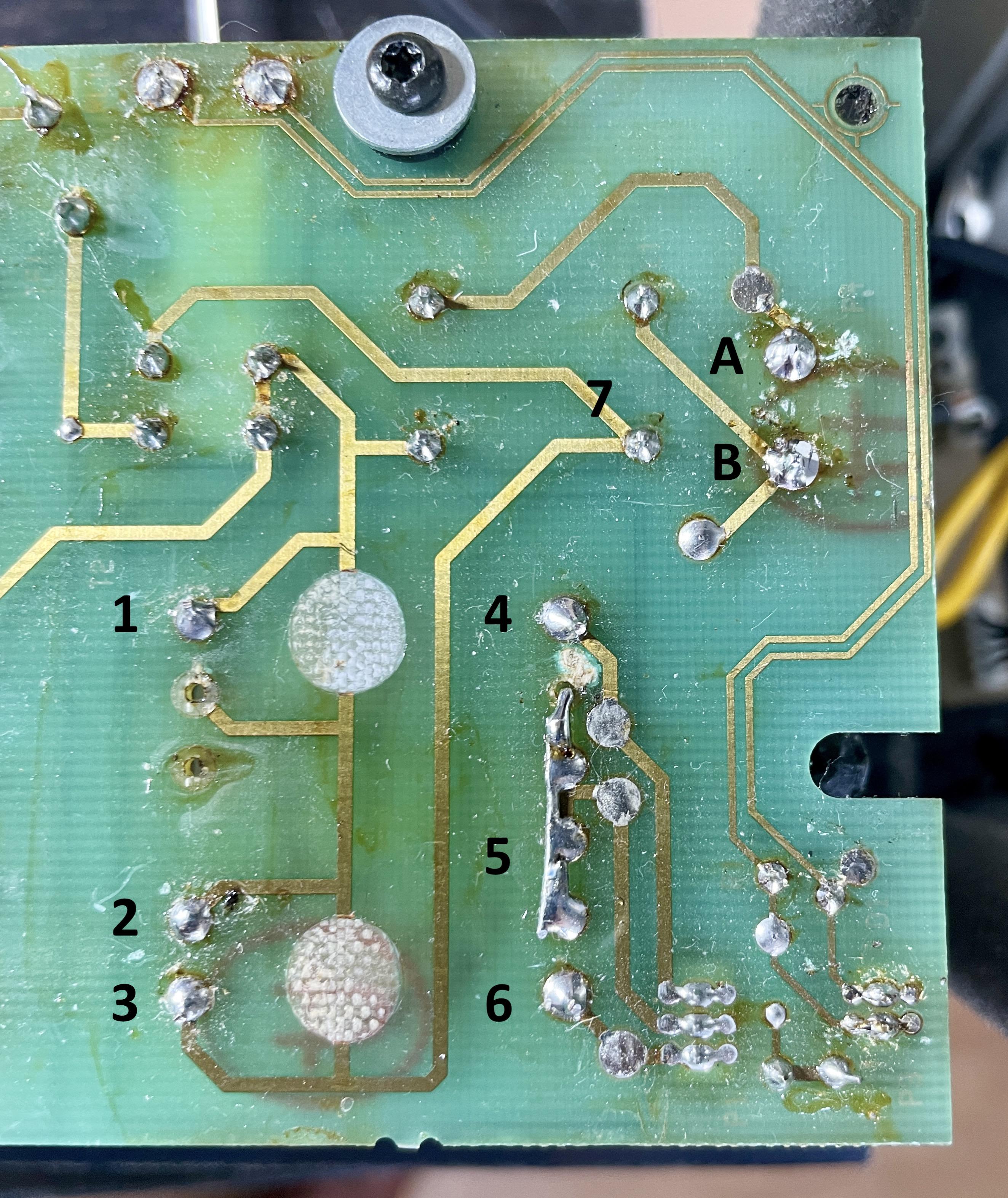
But, you should have continuity between A and 1, and between B (through 7) and 3.
- Between A + 1 = continuity.
- Between B + 3 = no continuity.
- Between B + 7 = continuity.
Piece of wire between 7 and 3 will solve it.(or at the point of where the trace is broken).
- I am gone do that.
Location: The Netherlands
Favourite Product: BeoSound 9000
My B&O Icons:
Thanks so much Tignum (fellow Dutchman!) This is really good information and the pictures speak for itself; wonderful.
There’s two things I am curious about how you handle that.
- I think I saw that you put the HPX tape on the length of the plastic grill, but both on the outside and the inside.
- Is that correct?
- Does it mean the cloth folds for about 1.5 cm to the inside of the grill, so also covering the notches? (Because B&O utilizes a very small edge where they stick the cloth, not covering the notches)
- If you make the cloth fold 1.5 cm how do you handle the the notches, so that they are not covered?
- How do you handle folding the cloth (without wrinkles) around:
- The circle shape of the top lid?
- Around the corners of the top lid?
- Did you order the cloth at Akustikstoff.com by the meter, or pre-cut?
Thanks again, looking forward to your tips.
Location: The Netherlands
Favourite Product: BeoSound 9000
My B&O Icons:
So I did some measurements again.
- Between 1 + 3 = 0 volts / and also no continuity.
Also checked for continuity between the incoming 230v connector and Pin 1 and 3 of the T2 transformer.
- Between A + 1 = yes, continuity.
- Between B + 2 = no continuity.
- Between B + 3 = no continuity.
But I also found something interesting:
- Between B + 7 = yes, continuity.
- Between 7 + 3 = no continuity. (Visually I cannot see any broken trace)

Location: The Netherlands
Favourite Product: BeoSound 9000
My B&O Icons:
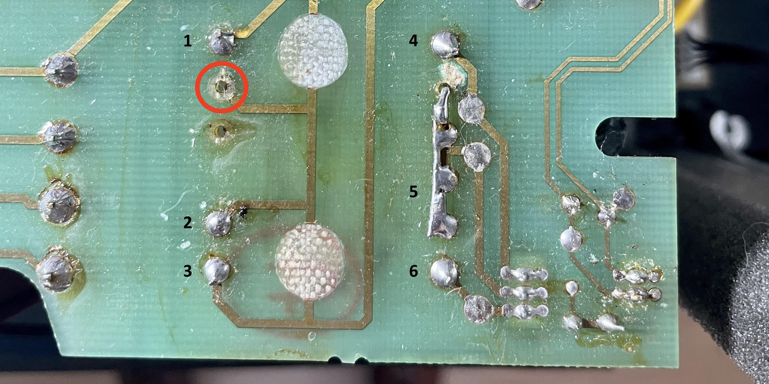
I assume you mean the point in the red circle Martin.
It looks like there should be solder. But there is no pin sticking through that hole, so there is nothing to solder.

Location: The Netherlands
Favourite Product: BeoSound 9000
My B&O Icons:
Thnx Beobuddy for responding!
This is what I measured for AC voltage (see also picture).Left side:
- 1 + 2 = 0v
- 2 + 3 = 0v
- 1 + 3 = 0v
Right side:
- 4 + 5 = 0v
- 5 + 6 = 0v
- 4 + 6 = 0v
Just to be complete, I also measured (again) if 230v AC is coming in at the 230v connector on this PCB. The result: positive, 230v has been measured.
Let me know if this is what you meant?
I assume the T2 transformer is dead. I am just wondering why the behavior of the T2 changed from:- Dead (no red LED at all), to
- Alive with errors (LED changing from red to green and back all the time), to
- Now dead again.
Interested in your comments and advise.
Location: The Netherlands
Favourite Product: BeoSound 9000
My B&O Icons:
I might need one.
What is the cost for the T2 trafo and what for shipping to The Netherlands?You can also send that via PM if you prefer.
Location: The Netherlands
Favourite Product: BeoSound 9000
My B&O Icons:
You mentioned that replacements for T2 on eBay are often wrong ones. I found this one on eBay: https://www.ebay.nl/itm/284404189940?hash=item4237cf8af4:g:TZAAAOSwLgpcPjdO
Questions:
- Is this one correct?
- How can I recognize the right one?
Location: The Netherlands
Favourite Product: BeoSound 9000
My B&O Icons:
Thnx Chekler!
Do you also have instruction info for putting new cloth on?
Location: The Netherlands
Favourite Product: BeoSound 9000
My B&O Icons:
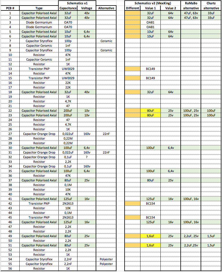
Very interesting to see this overview of 4 different versions Martin!
Also interesting that the top left and right and the bottom left, are different but have the same number on the top of the PCB and the same number on the label at the bottom.
So I have now component list for two versions, see the attached. The right one is based on the info mentioned by Mexking earlier in this thread. And added the alternatives for certain capacitors mentioned by RaMaBo and Chartz.
I think MexKing mentioned the left component list belongs to the PCB trace pattern also shown in this thread.
Question
- Are there really differences in the trace patterns between these two versions?

Location: The Netherlands
Favourite Product: BeoSound 9000
My B&O Icons:
In the process of re-building the original BeoGram 1000 Pre-Amp PCB …
I am now selecting the capacitors for my order. I noticed that it is hard to find the exact same values as the originals. For the voltage it is not such a problem, I can just step up the value for the voltage, and it will still work.
For the capacitance I am not sure. For instance, a capacitor with 32uF is hard to find. Though I do find 33uF. Also 1.6uF cannot be found, but 1.5uF is available.
Also 80uF, I cannot find.
Question
- Will choosing 1.5uF instead of 1.6uF work?
- Same; will choosing 33uF instead of 32uF work?
- Same; will choosing 100uF instead of 80uF work?
- Same; will choosing 150uF work instead of 125uF?
PS. I have searched via:
- https://www.nichiconcapacitors.com/shop/
- https://nl.rs-online.com/web/c/passive-components/capacitors/aluminium-capacitors/
- https://nl.farnell.com/c/passive-components/capacitors/aluminium-electrolytic-capacitors/leaded-aluminium-electrolytic-capacitors
Location: The Netherlands
Favourite Product: BeoSound 9000
My B&O Icons:
Just to be sure, are you looking only for the rubber feet, or also the metal bolts?
Location: The Netherlands
Favourite Product: BeoSound 9000
My B&O Icons:
Felt is an option.
Though I use rubber feet by Delock 10 x 3 mm. These fit in size.
https://www.delock.com/produkt/18309/kaufen.html
Location: The Netherlands
Favourite Product: BeoSound 9000
My B&O Icons:
-
AuthorPosts