
Forum Replies Created
-
AuthorPosts
-
 Moderator
When (if) you remove the top cover, be very careful to watch that any small pieces do not fall out. Here’s what you should see:
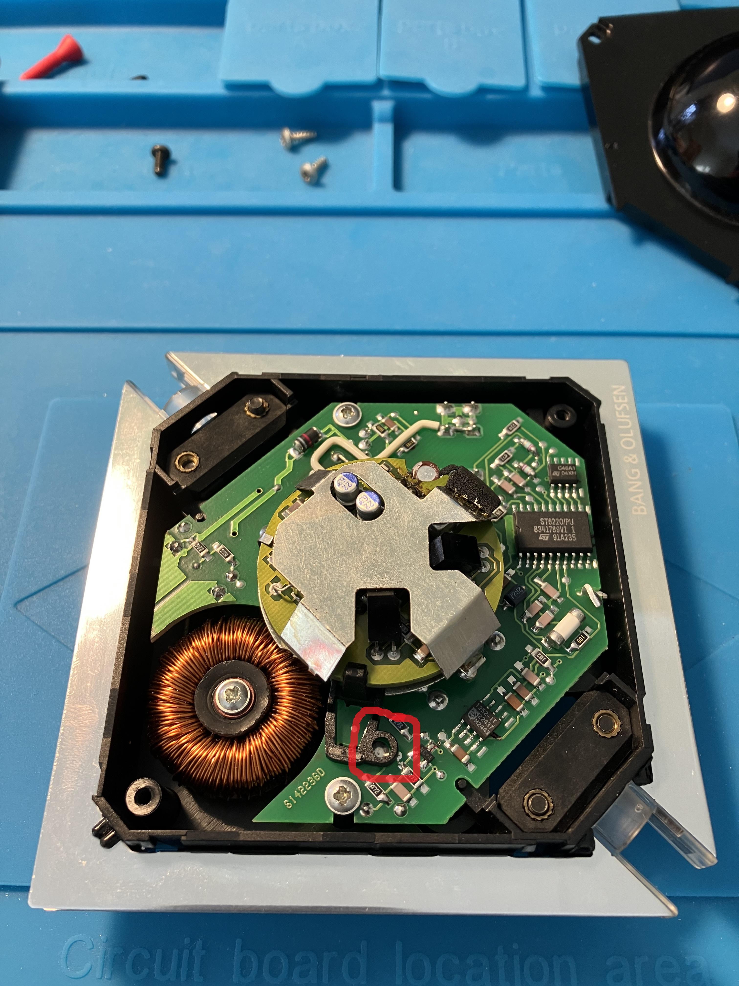
The red annotation is where the little contact piece sits – mine is missing. From memory it’s like a short rubber (conductive) tube about 5mm long, which sits tall enough to contact the silver area of the underside of the dome (which has to be fitted the right way around for it to make contact – so check this if the contact piece is present).
You can actually test the touch sensor circuit by touching the small solder pad in the circle with a metal object, but stay away from the mains voltages also present on the board!
My LC2 ‘repair’ thread is here (although I still haven’t fixed the IR sensor circuit or replaced the contact strip on mine!): https://forum.beoworld.org/forums/topic/lc2-repair/
Location: Warwickshire, UK
My B&O Icons:

From memory it won’t work with the wrong bulb. Try it with an old fashioned bulb of min 40w before removing the cover!
Edit: I think the light circuit needs a small current running through the bulb for it to work properly, hence the need for an old fashioned bulb.
Location: Warwickshire, UK
My B&O Icons:
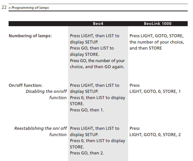
Beo4 programming is in the manual, but you have to be touching the upper dome whilst pressing the buttons on the remote.

So if the touch sensitive surface is not working then you will not be able to program it.
If you remove the top cover there is a small contact strip (that is easily lost) that provides contact between the PCB and the capacitive touch sensitive surface. If this is missing, or lost, then the touch sensor will not work.
Location: Warwickshire, UK
My B&O Icons:
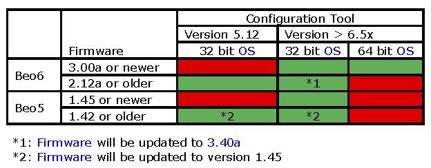
You may need to find a PC with a 32-bit OS:

Location: Warwickshire, UK
My B&O Icons:
My Beoport and BL3500 are connected at the moment so let me know if you want me to check anything on the ‘normal’ Beoport/PC setup!
I am not sure how LP2 does Beoport Option setting, but I have found that I can only get anything out of the BL3500 if the Beoport is in Opt 2. With this setup N.MUSIC, N.RADIO, PC all work. With Beoport in Opt 6 or 0, the only BL3500 IR command that will work is a long press to turn everything off. Other selections just come on (the screen) and straight off.
Location: Warwickshire, UK
My B&O Icons:
the IR eye shows the red light and react to the remote commands (other led blinking) but doesn’t pass commands to the Beoport. LP2 also doesn’t deter the eye.
If the Beoport is still in Opt 0 it won’t respond to the IR eye.
Location: Warwickshire, UK
My B&O Icons:
Like this!

Location: Warwickshire, UK
My B&O Icons:
I know that mine was with a PC, but I needed to put the Beoport in Opt 2, and the BL3500 in L.OPT 6 for it to work. I had the IR sensor unplugged to avoid a conflict in the same room.
Location: Warwickshire, UK
My B&O Icons:
I can’t view the attachment because it comes up as a heic file. Can you ‘insert image’ instead using the picture icon above the visual box that you type in? Many thanks!
Location: Warwickshire, UK
My B&O Icons:
Yes that does sound like a SW problem with the BL2000.
Does the BL2000 start the BS9000 when you press CD in the link room?
Does the BS9000 start playing the Airport Express when A.TAPE is pressed?
Once the BS9000 is already playing the Airport Express, does the BL2000 start playing when you press its PLAY button on the front?
Location: Warwickshire, UK
My B&O Icons:
As MM stated above your inability to select A.AUX in some link rooms is probably related to SW versions:
The minimum SW levels required for A.AUX on following devices is as follows. (The SW version may be written on the label, but some may have been updated without being amended.)
Beolink Active: SW 1.5
Beolink Passive: SW 1.5
BeoLab 2000: SW 1.5 (TBC – it certainly needs greater than 1.1, which doesn’t work)
BeoLab 3500: SW2.0
On the BL3500 you can check the SW level of the BL3500 by pressing MENU MENU 0 0 GO (or MENU 0 0 GO for early versions). Note that SW 2.1 and above will enable you to display PC (instead of V.AUX), N.RADIO (instad of PHONO) and N.MUSIC (instead of A.TAPE 2).
You can sometimes select A.AUX from non-compatible link-rooms by selecting a ‘spare’ audio source (eg A.MEM /A.TAPE), but only if that source is not used elsewhere in your system. You would have to reconfigure your system to do that. The other workaround is simply to activate (unmute) a link room when A.AUX is already playing elsewhere.
Regarding the Beo4 differences, the newer buttons usually give out the same IR commands as the earlier versions, so A.MEM is the same IR command as A.TAPE. A full list is here: https://forum.beoworld.org/forums/topic/beo4-and-beolink-1000-remote-shortcuts-and-equivalent-button-presses/
Location: Warwickshire, UK
My B&O Icons:
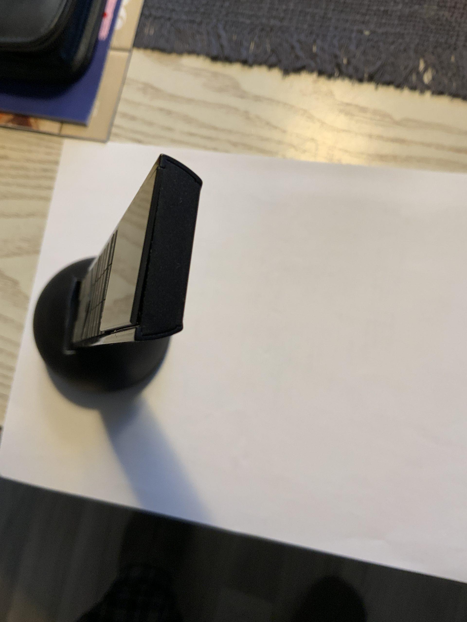
The small clamper version is shinny and the big clamper is mat.
EDIT: unless you replace the whole fascia, sorry.
With this:https://www.ebay.co.uk/itm/284633589979
Location: Warwickshire, UK
My B&O Icons:
I would look for a later software version (or latest SW, like Carolpa’s) if I was looking for a BS3000, rather than worrying about clamper size. Obviously the earlier ‘small clamper’ versions are more likely to have earlier software, unless they have been updated.
If you search BS3000 on UK eBay they often show photos of the labels so you can get a good idea of Type Numbers, SW versions and clamper size.
Location: Warwickshire, UK
My B&O Icons:
The result almost the same as when I injected 3V to the PL connector in the 1611. The BC6 turns on on an Audio connection when the Beoport starts. The TV doesn’t turn off or change input when the Beoport software is closed og the Beoports power is removed. In conclusion, nothing new regarding this, but at least it has now been tested. It might be that it will only work in combination with datalink signals on pin 6 of the AAL conenctor.
There could be one way of testing this a bit further. With a ‘proper’ audiomaster (such as BC2300) connected to the BL1611 and ML to TV. Connect PL and AAL from BC2300 to BL1611. TV in V.OPT2, BC2300 in A.OPT 0. Then use the BC2300 front panel to turn on (eg) CD, through TV speakers. Then unplug the PL connection and turn the BC2300 off, again from the front panel. If this turns the TV off then it’s using AAL/datalink.
Location: Warwickshire, UK
My B&O Icons:
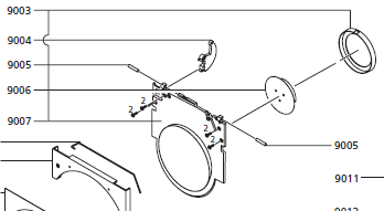
If you look at the service manuals on the site, then the one for the BS3000 shows the small clamper, and then one for the BS3200 shows the large clamper.
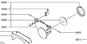
Comparing part numbers between the two schematics, the only new part number is the ‘cover f/clamper’. (9007 in the diagrams below)
BS3000:

BS3200:

EDIT: And there’s a thread here where Joeyboygolf confirms that they are interchangeable: https://archivedforum.beoworld.org/forums/t/9900.aspx
Location: Warwickshire, UK
My B&O Icons:
Did I read somewhere that the ‘small clamper’ was abandoned because it exposed most of the spinning disc, thus flashing light reflections from the surface (depending on CD artwork), and therefore risks triggering epileptic fits? I can only have read this on Beoworld or in Tim Jarman’s book!
Location: Warwickshire, UK
My B&O Icons:
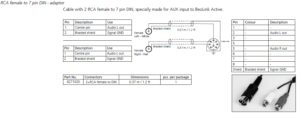
Today I had a quick look at the Active’s PC socket audio output pins 3 and 5, using pin 7 as ground.
Basically as long as the BL Active is activated, then PC pins 3 and 5 provide a fixed line-level audio output of whatever is playing on the Active’s ML input. This is even the case when the Active itself is playing what is connected to PC input pins 4 and 2 (note that pins 3 and 5 do not output the PC input source, even if the ML input is turned off first).
I suppose that this line-level output from ML could be useful to someone who wants to connect to another (make) system in a link room, or as an input into a PC sound card.
Location: Warwickshire, UK
My B&O Icons:
Steve used to make a cable for this! MM
And B&O: Might be still available?

Location: Warwickshire, UK
My B&O Icons:
I can confirm that these connections are correct. Data – and Data + are the differential data lines and are the same as pin 1 & 2 on the Masterlink socket. The SL_config works like the ML_config in defining direction of data.
Thanks Keith – I don’t think I’ll be able to do much with the data etc, and will just have a think about other uses for the pin 3 and 5 audio outputs (if they work). Thinking about these, the user manual for the Beolink PC shows a ‘SOUND IN – no connection; for future use’. I think that ‘SOUND in’ implies ‘a sound into a computer’, so perhaps the Beolink Active replicates this with a line-level sound ‘into the computer’. Perhaps B&O envisage people wanting to record digitally on their PCs, or do some processing on the computer’s sound card?
The later Beoport has a (usually covered with a sticker) audio output that could be used for the same purpose.
Location: Warwickshire, UK
My B&O Icons:
This is all a bit confusing so far! Other than the first couple of posts I haven’t done anything yet, but thanks for the input!
And for info there’s a BeoLink PC Office 1647 on UK eBay with a few pictures here: https://www.ebay.co.uk/itm/304770789938
Location: Warwickshire, UK
My B&O Icons:
-
AuthorPosts