


Home › Forums › Product Discussion & Questions › BeoLink › Beolink Active 1636 PC Input
- This topic has 44 replies, 6 voices, and was last updated 2 years, 7 months ago by
 Madskp.
-
AuthorPosts
-
20 January 2023 at 08:02 #43108
 MadskpGOLD Member
The Beolink PC Office and Beolink Active type number 1636 to 1639 inclusive are exactly the same hardware box. Beolink PC Office Type number 1640, 1647, 1648 , 1649, 1668 and 1669 is the Beolink Active above with the PC office software.
ok, but the hardware box for the Beolink PC office look very different:
https://archivedforum.beoworld.org/forums/t/42383.aspx
of course the internals can still be the same
Location: Denmark
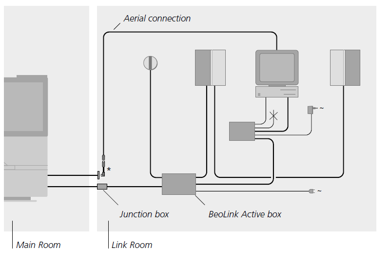
20 January 2023 at 11:59 #43100Now that we have explored the Beolink Converter 1611, and found some very useful ‘new’ functionality, I’d like to have a more in depth look at the Beolink Active 1636 – the later model with the PC input.
The PC input was introduced to add a ‘local source’ (such as a computer) to ML linkrooms. This source can be selected using PC, and cannot be distributed over the rest of the ML system.
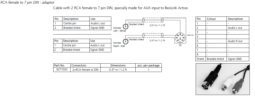
Use of the PC input requires a ‘special’ connector that will send L, R and Gnd audio to pins 2, 4 and 7 respectively (rather than the more typical 5, 3, and 1). I have made a cable and tested this recently.
As far as I know it is not possible to use the BL Active ‘stand-alone’ – with no ML connected. I have tested such a setup (with the BL Active in L.OPT 6) and there is no response to the PC input.
Searching the old forum I found a post by Vienna that gives the pin configuration of the PC input as follows:
“PC-Socket” on BeoLink Active 1636 – pin configuration – (Source: BeoWise)
1. SL-config
2. LEFT IN
3. Left out
4. RIGHT IN
5. Right out
6. Data –
7. GROUND / SHIELD
8. Data +So my first question before I start experimenting: Does anyone know what pins 1, 6 and 8 are for?
I will have a look at pins 3 and 5 but suspect that they are either a line or PL-level output using pin 7 as ground (rather than pin 2 gnd in a normal PL output socket). I will check if they output just the local source or just the ML source, or both (or none!)
A service manual for the 1636 version would be useful (we only have the earlier 1616/1618 version on the site, with two PL sockets).
I will report back here with any findings.
Location: Warwickshire, UK
My B&O Icons:
 20 January 2023 at 12:18 #43101
Further to the above, it would seem that the PC input was designed to be used with BeoLink PC Office (not the later Beolink PC2 or Beoport). I would think that the extra pins in the PC socket actually gave this Beolink PC Office all the functionality of being connected to ML (and PL), without being connected to ML (or PL)! Clearly none of this was needed when the Beolink PC2 was introduced with its own ML/PL sockets.
EDIT: This from the Beolink PC Office User Manual – it’s the box nearest the computer:

Location: Warwickshire, UK
My B&O Icons:
20 January 2023 at 13:37 #43102I’m reading carefully.
Looks like we’re gonna write the next B&O related book: “B&O black boxes mysteries revealed”. 🙂
Location: Paris France
20 January 2023 at 17:48 #43103“PC-Socket” on BeoLink Active 1636 – pin configuration – (Source: BeoWise)
1. SL-config
2. LEFT IN
3. Left out
4. RIGHT IN
5. Right out
6. Data –
7. GROUND / SHIELD
8. Data +So my first question before I start experimenting: Does anyone know what pins 1, 6 and 8 are for?
I can confirm that these connections are correct.
Data – and Data + are the differential data lines and are the same as pin 1 & 2 on the Masterlink socket. The SL_config works like the ML_config in defining direction of data.Location: Hampshire, England
20 January 2023 at 18:32 #43104Steve used to make a cable for this!
MM
Location: Flensborg————Danmark
20 January 2023 at 18:44 #43105MadskpGOLD MemberFurther to the above, it would seem that the PC input was designed to be used with BeoLink PC Office (not the later Beolink PC2 or Beoport). I would think that the extra pins in the PC socket actually gave this Beolink PC Office all the functionality of being connected to ML (and PL), without being connected to ML (or PL)! Clearly none of this was needed when the Beolink PC2 was introduced with its own ML/PL sockets. EDIT: This from the Beolink PC Office User Manual – it’s the box nearest the computer:
something doesnt fit in my head. The PC input is only shown in a usermanual called 2007 on Beoworld. The original Beolink PC office was only availeble from 1999-2001 and the superseeded by Beolink PC Office 2/Beoport. Off course there could be a manual for Beolink active inbetween that I dont see.
sometimes I miss a printed date in those manualsLocation: Denmark
20 January 2023 at 19:08 #43106MadskpGOLD MemberFurther to the above, it would seem that the PC input was designed to be used with BeoLink PC Office (not the later Beolink PC2 or Beoport). I would think that the extra pins in the PC socket actually gave this Beolink PC Office all the functionality of being connected to ML (and PL), without being connected to ML (or PL)! Clearly none of this was needed when the Beolink PC2 was introduced with its own ML/PL sockets. EDIT: This from the Beolink PC Office User Manual – it’s the box nearest the computer:
something doesnt fit in my head. The PC input is only shown in a usermanual called 2007 on Beoworld. The original Beolink PC office was only availeble from 1999-2001 and the superseeded by Beolink PC Office 2/Beoport. Off course there could be a manual for Beolink active inbetween that I dont see. sometimes I miss a printed date in those manuals
ok researched a little more and the picture on this site tell that Beolink Active 1636 was there at the same time as the first PC office.
The original Beolink active may only have been availeble for a few years then
Location: Denmark
20 January 2023 at 19:25 #43107ok researched a little more and the picture on this site tell that Beolink Active 1636 was there at the same time as the first PC office.
Bang Olufsen B&O Beolink PC Office / Active Service Manual *Original*
The original Beolink active may only have been available for a few years then
The Beolink PC Office and Beolink Active type number 1636 to 1639 inclusive are exactly the same hardware box.
Beolink PC Office Type number 1640, 1647, 1648 , 1649, 1668 and 1669 is the Beolink Active above with the PC office software.
Location: Hampshire, England
20 January 2023 at 21:13 #43109This is all a bit confusing so far! Other than the first couple of posts I haven’t done anything yet, but thanks for the input!
And for info there’s a BeoLink PC Office 1647 on UK eBay with a few pictures here: https://www.ebay.co.uk/itm/304770789938
Location: Warwickshire, UK
My B&O Icons:
20 January 2023 at 21:23 #43110I can confirm that these connections are correct. Data – and Data + are the differential data lines and are the same as pin 1 & 2 on the Masterlink socket. The SL_config works like the ML_config in defining direction of data.
Thanks Keith – I don’t think I’ll be able to do much with the data etc, and will just have a think about other uses for the pin 3 and 5 audio outputs (if they work). Thinking about these, the user manual for the Beolink PC shows a ‘SOUND IN – no connection; for future use’. I think that ‘SOUND in’ implies ‘a sound into a computer’, so perhaps the Beolink Active replicates this with a line-level sound ‘into the computer’. Perhaps B&O envisage people wanting to record digitally on their PCs, or do some processing on the computer’s sound card?
The later Beoport has a (usually covered with a sticker) audio output that could be used for the same purpose.
Location: Warwickshire, UK
My B&O Icons:
20 January 2023 at 21:28 #43111Steve used to make a cable for this! MM
And B&O: Might be still available?

Location: Warwickshire, UK
My B&O Icons:
21 January 2023 at 14:03 #43112Today I had a quick look at the Active’s PC socket audio output pins 3 and 5, using pin 7 as ground.
Basically as long as the BL Active is activated, then PC pins 3 and 5 provide a fixed line-level audio output of whatever is playing on the Active’s ML input. This is even the case when the Active itself is playing what is connected to PC input pins 4 and 2 (note that pins 3 and 5 do not output the PC input source, even if the ML input is turned off first).
I suppose that this line-level output from ML could be useful to someone who wants to connect to another (make) system in a link room, or as an input into a PC sound card.
Location: Warwickshire, UK
My B&O Icons:
21 January 2023 at 16:41 #43113MadskpGOLD MemberGuy wrote:
I suppose that this line-level output from ML could be useful to someone who wants to connect to another (make) system in a link room, or as an input into a PC soundcardfrom the top of my head this could be a way to feed the line in on a Sonos system, and the do the volume control on the Sonos units.As for the PC input it could be a poor mans link room where the PC’s own speakers are used. Control of music from the master unit (except volume control) would still be possible withe the IR eye and a BEO remote. Of course this could also be done through the PL connector with volume control with BEO remoteLocation: Denmark
3 December 2023 at 08:58 #43120I will do some testing when I have time this week. There have been unsuccessful attempts to use BL Active stand-alone in the past, such as here: https://archivedforum.beoworld.org/forums/t/31173.aspx
My BL Actives are all Type 1636 SW1.1.
Location: Warwickshire, UK
My B&O Icons:
3 December 2023 at 09:04 #43121MadskpGOLD MemberI will do some testing when I have time this week. There have been unsuccessful attempts to use BL Active stand-alone in the past, such as here: https://archivedforum.beoworld.org/forums/t/31173.aspx My BL Actives are all SW1.1.
I will try that too. I have both a SW 1.1 and 1.6 as far as I remember.
One thing I will try to test is if it will run with a BLC 1614 connected on Masterlink, just to check if a Audio- or videmoster is required, or if its just the presence of Masterlink voltage, and or signals
Location: Denmark
3 December 2023 at 16:46 #43114MadskpGOLD MemberGuy wrote: “PC-Socket” on BeoLink Active 1636 – pin configuration – (Source: BeoWise) 1. SL-config 2. LEFT IN 3. Left out 4. RIGHT IN 5. Right out 6. Data – 7. GROUND / SHIELD 8. Data + So my first question before I start experimenting: Does anyone know what pins 1, 6 and 8 are for? I can confirm that these connections are correct. Data – and Data + are the differential data lines and are the same as pin 1 & 2 on the Masterlink socket. The SL_config works like the ML_config in defining direction of data.
Hawing done som continuity Measurements inside the Beolink Active I can confirm that the data pins and the SL_config Pin has direct connections to the Masterlink connector as follows, and must be Masterlink data in a DIN connector.
Pin 1 SL-config is Masterlink ML sense
Pin 6 Data – is Masterlink Data –
Pin 8 Data + is Masterlink Data +Location: Denmark
3 December 2023 at 19:07 #43115I had forgotten about this thread when I posted in ‘BL1611 innovative configurations’! Anyway, if/when I investigate the BL Active further I will post here.
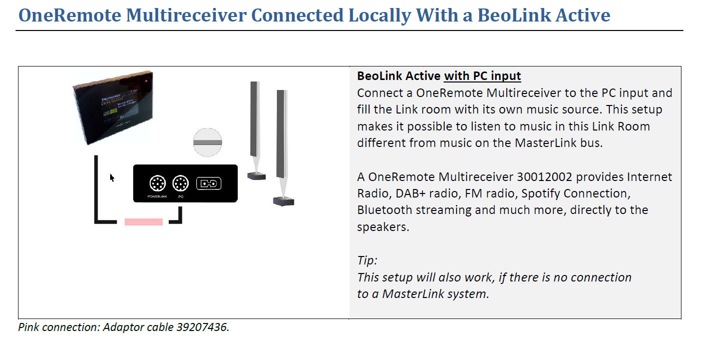
One other thing that intrigues me is that some OneRemote documentation implies that the BL Active can be used stand-alone with the OneRemote radio as an input – look at the ‘tip’ in the diagram below:
 I wonder if the adaptor cable does something funny to make stand-alone operation possible?
Location: Warwickshire, UK
My B&O Icons:
3 December 2023 at 19:31 #43116MadskpGOLD MemberOne other thing that intrigues me is that some OneRemote documentation implies that the BL Active can be used stand-alone with the OneRemote radio as an input – look at the ‘tip’ in the diagram below: I wonder if the adaptor cable does something funny to make stand-alone operation possible?
Yes thats intriguing. Looking at the adapter itself (PCSNUT) https://shop.oneremote.dk/shop/69053-oneremote-/4271-pcsnut-adaptor-cable/ it doesn’t seem like something special, and based on our knowledge about the ASNUT and VSNUT adapters from Oneremote they are just passive adapters.
I wonder if the setup manual describes a speciel setup code for this setup?
My best guess is that this setup could change the signals from the Oneremote radio from datalink to Masterlink. We already know it can change between the two different datalink formats.
If it does change the signals to Masterlink then the Beolink active will get a Masterlink signal from the Oneremote radio via the PC DIN connector which as mentioned earlier has its data pins directly connected to the Masterlink connector. If the Oneremote radio the work as a Audio Master it should be sufficient to drive the Beolink Active.
Hope this makes sense
Location: Denmark
3 December 2023 at 19:45 #43117MadskpGOLD MemberI found this setup manual from Oneremote https://doc.oneremote.dk/Vejledninger/30012002S5dk.pdf Only in Danish though.
On page 27 it describes that it can be connected to the PC connector in all Link rooms which does not correspond with my theory about it acting like and audio Master.
However the setup is also described as direct mode which is via an IR reciever, so there might not be any data connection in place. That makes sense when used in a Masterlink system with other unit.
It does however not explain how it should be used with the Beolink Active as a stand alone unit which as far as I know does not work under normal circumstances
Location: Denmark
-
AuthorPosts


 I wonder if the adaptor cable does something funny to make stand-alone operation possible?
- You must be logged in to reply to this topic.