


Home › Forums › Product Discussion & Questions › BeoMaster › First start of a BM6000 “not Working”
- This topic has 36 replies, 6 voices, and was last updated 3 years, 4 months ago by
 Glitch.
-
AuthorPosts
-
15 December 2022 at 02:14 #41450
 chilibtBRONZE Member
Hi,
I just got a Beomaster 6000 that was “Not working” The first thing noticed was the Lower of the two fuses beside the transformer was partially out of its holder. I want to make sure I am careful to not make things worse on start up.
I have read that Variac’s are good for initial start up of tube equipment, but it appears opinions are mixed on solid state equipment.
What is the best way to start this up for the first time?
Location: canada
Favourite Product: Beocord 9000
Signature: chilibt
15 December 2022 at 22:13 #41451 BRONZE Member
I have always used variacs while monitoring the current. I assume you meant that one side of the fuse was not making contact.
16 December 2022 at 10:27 #41452Die_BogenerBRONZE MemberI use a special transformer, switchable in 10V steps… 10 – 240V, with Volt and Ampere Display.
Instead of a fuse a 220V light bulb can help, if there is a shortcut problem… a light goes on.
16 December 2022 at 12:49 #41453GlitchBRONZE MemberIn addition to the above suggestions, there is also the option for testing the various boards or subsystems separately. For example the power supplies can be tested with the other boards disconnected. The main amp can be tested using bench power supplies, etc.
My main goal in this situation is to avoid damaging parts that are hard or impossible to replace. For a BM6000, the microprocessor would be the main concern. Make sure that the 5v and 6.5v supplies to Board 2 are in spec.
I would also remove and test the large capacitors on the power supply before applying any power.
The “best way” to power-up an old piece of equipment depends a lot on your goals (how serious you are about preserving the machine) and resources (what test equipment you have to work with). For some people, all they need to do is plug the machine into an outdoor outlet if their main goal is simply not to stink up the house with electronics smoke ;-).
It would be easier for people to provide detailed help if you provide more information about YOUR goals and resources.
Glitch
16 December 2022 at 15:35 #41454chilibtBRONZE MemberThanks for the advice,
This is a 120V unit. Preservation of This receiver is the goal. I currently have a dc power supply, multimeters, and could buy a variac if it is the best way to start the test of the unit. This has one fuse out of its holder on one end of the holder-not touching, and was sold as “not working” …making me think that the fuse out of place may be why it was “not working”. There is no smell or visual damage inside so it gives more evidence that it could be a out of place fuse as the culprit. Restoration to operational is the goal.
The Variac was the unknown to use for me as the damage of the main IC was my concern. I read conflicting accounts on the use of a variac with modern (non tube) receivers and most information on variacs are tube focused.
I have another unit which has a problem with the amp board shutting down the receiver, both these units have some scuffs on the aluminum. Ideally I will make one unit the best exterior and a fully restored interior by using all best parts, and the second will have the worst exterior panels but be restored and have a functioning receiver (the exterior aluminum may not look as nice).
I like the idea of testing the main Power supply (PS) capacitors and unplugging the boards to test the PS first. Would a variac be good here or just give it a try once the caps were determined as OK.
Location: canada
Favourite Product: Beocord 9000
Signature: chilibt
16 December 2022 at 15:41 #41455chilibtBRONZE MemberI also read that starting with a Variac should be done at 70 or 90 volts and not lower. If a variac were to be recommended, then which initial voltage would be recommended?
Location: canada
Favourite Product: Beocord 9000
Signature: chilibt
16 December 2022 at 16:17 #41456GlitchBRONZE MemberA few months ago I did a similar project of getting several BM6000’s (that were put away “broken”) working again. I have a Variac, but didn’t bother pulling it out of storage for this project since I didn’t think there was much risk at destroying anything irreplaceable in the power supplies. However, when I did power-up the main supply, Board 16, I used a rig that has a light bulb in series. The order I did things was:
- Test the capacitors
- Test the main power supply (Board 16)
- Test the CPU power supply (Board 6)
- Test the main amp (Board 9) with a bench power supply. I brought the voltage up slowly with current limits in place. This is a good time to adjust the no-load current and offset voltage.
- Reassemble everything except the power connector to the main amp and test with the light bulb rig. It is hit or miss that the receiver will start in this configuration since the RESET circuit will likely trip.
- Test with the main amp power connected and the light bulb rig.
- Try power-up connected directly to the mains (only if step 5 & 6 looks good)
I recall that there was a signal or two that used the edge connectors as a safety circuit which kept the receiver from powering-up if the connector was off. These can be found by tracing through the schematics.
Glitch
16 December 2022 at 20:58 #41457chilibtBRONZE MemberThank you for an easy to follow checklist, it is greatly appreciated.
As a hobbyist (Not Tech) of course this leads to more questions that you can hopefully answer:
Test the capacitors OK (main power caps are to be tested)
Test the main power supply (Board 16): By regular mains power after checking caps and disconnecting other boards?
Test the CPU power supply (Board 6): Using power from the main power supply board 16(above) once tested?
Test the main amp (Board 9) with a bench power supply. This is a part that could go bad for me, can you confirm (P34-1 [50v -] and P34-4 [50v+] to be the power pins, I brought the voltage up slowly with current limits in place. What current limits did you use? This is a good time to adjust the no-load current and offset voltage.
Reassemble everything except the power connector to the main amp and test with the light bulb rig (what bulb wattage? 60, 75 or higher? The specs say the amp has 50-300 watts consumption). It is hit or miss that the receiver will start in this configuration since the RESET circuit will likely trip.
Test with the main amp power connected and the light bulb rig.
Try power-up connected directly to the mains (only if step 5 & 6 looks good)Thanks again for your help in this start up process.
Location: canada
Favourite Product: Beocord 9000
Signature: chilibt
17 December 2022 at 00:51 #41458GlitchBRONZE MemberTest main power supply
- [PLUG OUT]
- Remove P41 & P42 from Board 16 and P34 from Board 9. Leave P40 connected on Board 16.
- [PLUG IN] Measure the 6.5v signal on pins 1 & 5 on P41. This may read high (~10v) since there is no load on it. Measure the 15v signal on pins 9 & 6 on P42. This should be very close to 15v. [PLUG OUT]
- Pull P19 on Board 6. Energize the rail voltage relay by connecting B16-P42-9 to B6-P19-8 and B16-P42-6 to B6-P19-10 (i.e. supply 15v to the relay)
- [PLUG IN] Measure the +50v and -50v rails at the capacitors. Measure the +32v signal at B16-P42-3 and B16-P42-9. This will also read high (~35v) since there is no load on it. [PLUG OUT]
- Reconnect P41 and P42 on Board 16. Leave P40 on Board 16 disconnected.
Test CPU power supply
- Remove P2 and P5 from Board 2
- [PLUG IN] Measure the CPU +5v on P5-1 and P5-3. This should be very close to 5.00v. Measure the +6.5v signal on P2-2 (it will still read ~10v) [PLUG OUT]
- Reconnect P2 and P5 on Board 2
- [PLUG IN] Measure the +6.5 signal on B2-P2-2. This should be close to 6.5v now. Measure the “other” +5v signal on B2-P2-3. This might read a few tenths of a volt high. [PLUG OUT]
Test Main Amp with Bench Power Supply
1. Connect to power supply
- B9-P34-1 -50v* * Start at about +-10v and work your way up
- B9-P34-2 GND
- B9-P34-3 GND (I can’t remember if pins 2 & 3 are connected on the board)
- B9-P34-4 +50v*
- B9-P31-3 GND**
- B9-P32-3 GND**
** The ground signals on P31 & P32 are not connected to the grounds on P34 on Board 9. I think B&O wired things this way to avoid a ground loop within the chassis.
2. Set power supply voltage to +-10v and the current to about 0.10A
3. Connect voltmeters to measure the Idle Current and Offset Voltage per the Service manual
4. [POWER ON] Adjust R110/R210 for an idle current “voltage” of around 5mV and R134/R234 for an offset voltage near 0.0v. The actual voltages are not critical now as long as they are below the 22mV and near the 0.0V that you are trying for at full voltage.
5. Increase the +- rail voltages in steps of say 10v at a time while watching the idle current and offset voltage and adjusting the trim pots as needed. You will need to increase to current limit as you go to about 0.3A
6. Work you way up to +-50v while keeping things in spec. [POWER OFF]
7. Wait for things to cool off to room temp
8. [POWER ON] Do a final adjustment per the service manual [POWER OFF]
At idle, all of my BM6000 draw about 0.19A on the -50V rail and 0.17A on the +50V rail.
For the light bulb wattage, I use a 150w bulb for most things. Other sizes should work as well. You won’t (hopefully) be drawing anywhere near the bulb rating since you aren’t trying to run the amp at full power. The bulb should stay very dim except when the the relay kicks on and the rail capacitors charge (it takes less than a second).
I just ran through the power supply steps on one of my BM6000’s to verify that I remembered what I did correctly. Please double check the procedures against the schematic (and common sense) to be sure that I didn’t make any typos, etc. The amp check-out procedure is from memory, so be more careful with that. Don’t hesitate to ask if it looks like I forgot a step or if my description isn’t clear.
BTW, I will sometimes hook up the main amp to a music source and speakers as part of the bench test. This can help provide confidence that all is well with the amp. It also saves the steps of install/remove if something else on the amp needs to be fixed.
Be sure to post results of your progress.
Glitch
18 December 2022 at 02:50 #41459chilibtBRONZE MemberThanks Glitch,
(I responded twice so far and get “errors” and lose the text. I am trying again.)
This is an amazing list of steps that will help me and others start up an “unknown” unit. Thank you very much!
I have some questions about grounding and test points, my questions are in bold:
Test Main Amp with Bench Power Supply
1. Connect to power supply
B9-P34-1 -50v* * Start at about +-10v and work your way up
B9-P34-2 GND What ground do I use, the chassis, the removed conector, of the Mains ground?
B9-P34-3 GND (I can’t remember if pins 2 & 3 are connected on the board) As above?
B9-P34-4 +50v*
B9-P31-3 GND** As above
B9-P32-3 GND**
** The ground signals on P31 & P32 are not connected to the grounds on P34 on Board 9. I think B&O wired things this way to avoid a ground loop within the chassis.2. Set power supply voltage to +-10v and the current to about 0.10A
3. Connect voltmeters to measure the Idle Current and Offset Voltage per the Service manual
4. [POWER ON] Adjust R110/R210 for an idle current “voltage” of around 5mV and R134/R234 for an offset voltage near 0.0v. The actual voltages are not critical now as long as they are below the 22mV and near the 0.0V that you are trying for at full voltage.
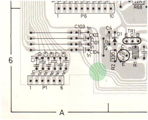
The Test points (TP) in the testing diagrams and schematics, list the TP on R244/243 and R144/143. The actual PCB has a different point indicated as printed on the Board. The printing shows the adjacent small Resister as the test point. I believe it is printed on the PCB wrong. I am attaching photos of the different boards and spots. Am I correct, the error is on the PCB?
Thanks again for the list. I will be working on and posting the results after Christmas.
Regards
Terry
Location: canada
Favourite Product: Beocord 9000
Signature: chilibt
18 December 2022 at 15:53 #41460GlitchBRONZE MemberWhat ground do I use, the chassis, the removed connector, of the Mains ground?
For something like this, I setup the bench power supplies using a floating ground. I use multiple supplies (in series) to get the voltages needed. Googling something like “lab power supply grounding” will get you a better explanation than I can provide as well as providing safety tips and identifying pitfalls.
I am attaching photos of the different boards and spots. Am I correct, the error is on the PCB?
The markings on the PCB might be a bit misleading, but are actually correct. If you look carefully, the small resistor is connected to the large green one via the traces on the circuit board. Clipping the test leads on the green resistors is the most convenient location. The positive lead goes on the right resistor if I recall correctly.
Glitch
18 December 2022 at 16:39 #41461chilibtBRONZE MemberThanks again, you are very generous with your knowledge.
I am cautious at the schematic interpretation (in case I miss something) and I thought they may be connected on the trace but it would need to be confirmed with removing the board from the heat sink… thus pushing the wires into another bending which can lead to trouble (I do not trust all disassembly to be trouble free).
I found on my current 6000 that the antenna connections have the smallest fragile wire in a solid nylon shield, breaking the wire easily and giving me the dreaded 78.8(or similar) display. It now makes me aware not to tear at the unit for reviews/repairs without a full understanding of the manual and visible information on the board.
Thanks for the bench test suggestion!
Location: canada
Favourite Product: Beocord 9000
Signature: chilibt
18 December 2022 at 17:33 #41462GlitchBRONZE MemberI thought they may be connected on the trace but it would need to be confirmed with removing the board from the heat sink
You can verify the connectivity between points on the front side of the board by using a multimeter in the “ohms” setting.
Yep, the wire on the coax cable to the FM board is precarious. I had to repair this connection on all of the BM6000’s that I have. The trick for this repair is to remove the pins from the white connector for soldering and adding strain relief when reassembling.
Also, care should be taken to not jostle the light bulbs on the display board. The wires to the bulbs are very delicate/brittle. Just closing the “lid” hard from the service position can provide enough of a shock to break the connections.
Glitch
18 December 2022 at 21:00 #41463chilibtBRONZE MemberGreat info, thanks,
I discovered the bulb issue before it was too late in the past (thanks for reminding me).
I like this info as a reminder, as I have not worked on these in a year and now -it is fresh in mind!
Location: canada
Favourite Product: Beocord 9000
Signature: chilibt
25 January 2023 at 23:08 #41464chilibtBRONZE MemberThanks for the excellent help! Here are the results:
First checked main 10000 uF caps, there was a slight vent of crust, so replaced with newer ones that tested good. (new were on order)
put fuse in
[PLUG OUT]
Remove P41 & P42 from Board 16 and P34 from Board 9. Leave P40 connected on Board 16.
[PLUG IN]the dim bulb lit up then the fuse blew. I investigated further and found the 2200 uF cap was now shorted. I replaced it with one on hand sand the unit worked! (except the keyboard).
The Cap set arrived and I thought the board 2 recap would be the best start. It did not bring the keyboard up and working. The ribbon cable is fine (c0ntinuity) the solder joints are ok.
Any thoughts on the keyboard fix?
The next issue is on board 8, It has a 10uF cap in place of the spec 22nF. attached picture. Should I put a 22nf back or replace the same 10uF? (pictures on this site shows others have the 22nF) I have another unit with the 10uF. Was this a factory improvement?
Location: canada
Favourite Product: Beocord 9000
Signature: chilibt
29 January 2023 at 12:53 #41465chilibtBRONZE MemberI did a test of the keyboard buttons and the contacts work, giving a response to the end of the connectors. Summary, the unit has full functionality using the remote, only the keyboard has no response when any key is pressed, and the keys apear to work.
Any suggestions what to look at next?
Location: canada
Favourite Product: Beocord 9000
Signature: chilibt
29 January 2023 at 18:52 #41466Hi,
Just saying but a Variac or a bulb don’t make much sense if you know what you’re doing. I’ve never used one in my 40 years of electronics.
Good luck with the repair.
30 January 2023 at 01:08 #41467chilibtBRONZE MemberThanks, good to know I figured experts would not need it.
As this was a “DOA” item with a fuse out of its holder, there was a question as to why the fuse was out. I was nervous to put the fuse in a try it, in case the problem damaged the main IC. In this case, the dim bulb actually told me there was a problem before the fuse blew . On investigation a bad capacitor was discovered.
So in this case it did not prevent anything it seems, it just slowed it down, and if I was faster I could have saved a fuse. I agree that a knowledgeable person could get by without it but I am less than that.
Thanks for the comment though!
I am still trying to find the keyboard problem and why the tested keyboard does not do anything. Any suggestions?
Location: canada
Favourite Product: Beocord 9000
Signature: chilibt
30 January 2023 at 08:32 #41468Hi
The problem with the keyboard could be a issue with IC 5 (STROBE) or the railvoltage for transistors T15 – 19 and TR 22. Look here for C 49 (1000uF)
These transistors should ” amplify” the strobe signal from IC 5, go to the LED displays and via resistors R3 – 8 to the keyboard.
The strobe signal is fed via the keyboard to the uPC IC 4 PINs 8 – 12
If there is no strobe signal present the keyboard won’t work.
Regards
Christian
30 January 2023 at 14:50 #41469GlitchBRONZE Member -
AuthorPosts
- You must be logged in to reply to this topic.