


Home › Forums › Product Discussion & Questions › BeoMaster › First start of a BM6000 “not Working”
- This topic has 36 replies, 6 voices, and was last updated 3 years, 4 months ago by
 Glitch.
-
AuthorPosts
-
28 February 2023 at 23:12 #41470
 chilibtBRONZE Member
Thanks for the great suggestions! We have had health setbacks here so work has been slow.
Here is the solution I found thanks to all the help you gave. (And new problems).
The above suggestions led me to track the various components “continuity” in the keyboard circuit. After many hours of work I found an intermittent issue in the displays would go dead randomly. This added confusion to the situation. Finally I found a hairline scratch where someone probably removing the shield over the CPU area slipped (very hard to see). I ran jumpers as the trace repair was too small for my setup.
It worked, and in total 11 traces were found to be cut! Now she is almost working perfectly. Two new issues were discovered:
The signal strength LED’s (red) do not light up. Since I replaced all the trimmers in the unit and Caps, Could this be an adjustment on a trimmer? I tried 6R11 without effect. So I am thinking it may be on Board 8. I do not have a Signal gen etc. to set up things on Board 8. Do board 8 trimmers affect this? Perhaps adjusting a trimmer may give them life? It is at my limit to figure this one out.
The second is the tuner will not go lower than 88Mhz but will go up higher than 110Mhz. How is this adjusted?
Thanks again guys!
Location: canada
Favourite Product: Beocord 9000
Signature: chilibt
28 February 2023 at 23:36 #41471chilibtBRONZE MemberThe arrow in the photo was where 11 traces were cut, the white wires are my jumpers.
Location: canada
Favourite Product: Beocord 9000
Signature: chilibt
2 March 2023 at 15:34 #41472GlitchBRONZE MemberBased on your earlier descriptions, the “no keyboard” issue pretty much “had” to be broken traces. It is interesting to hear about where and how the breaks occur. Many times it is due to a stressed or warped circuit board.
The “no signal strength LED” issue is (most likely) either an open circuit between Board-8 or Board-6 and the LEDs on Board-2, or the trim pots on Board-8 being out of adjustment. It could also be a solder bridge or a number of other self-inflicted issues. I’d start by checking for cold solder joints on the edge connectors and measuring for continuity between the signal origins and destinations.
As far as the FM trim pots (Board-8), you might to check out this thread: Strategy for Changing Capacitors and Trim Pots on FM Tuner. My experience is that the settings on the FM board are pretty robust if all you want is to receive strong FM stations with poor sound quality. The settings are very sensitive for a properly aligned tuner with good sound quality and reception sensitivity. The odds of properly aligning the FM without measurement equipment are pretty much nil.
Setting the Tuning Voltage with 8R44 and 8R46 will likely fix your tuning range issue. However, it these are far enough out-of-adjustment to give you the described symptoms, you probably have many other FM alignment issues.
Glitch
2 March 2023 at 16:02 #41473chilibtBRONZE MemberThanks Glitch! my thoughts were the same about traces, except the intermittent display threw me off. I started to think a cap or TR was changing in temperature causing the problem, with the displays then they may affect the keyboard. I never thought so many traces could have been cut with one microscopic scratch.
The tuner issues you describe will mean a visit to a shop with the correct equipment. Luckily that can wait as the frequencies listened to in my area are not affected and comparing my other non B&O receiver tuner to this one seems like the sound is ok as well.
I am in the process of continuity tests and solder joints/shorts, so far nothing suspicious found.
Interesting recent issue:
I was putting things back together and lost one of the repaired traces power to the keyboard, Affecting P1, Vol 40 and Standby buttons. all else was OK.
I removed the shield on the inside and looked at all the possible solder connections , and tested it again and it was ok. Put it back together and it happened again.
On the 3rd try I finally discovered that the shield of board 2 there is a metal tab which is on the bottom (a wire guide perhaps). it was making contact with the board in the last 1mm near the bottom. This rubbed the varnish off the bottom trace, exposing a tiny sliver of copper and grounded the trace to the shield. One easy bend of the tab and the problem was gone. Whew. (photo)
Lesson learned was to check for any contact of metal to the PCB’s even if it looks intentional.
Location: canada
Favourite Product: Beocord 9000
Signature: chilibt
2 March 2023 at 18:45 #41474chilibtBRONZE Membera new item, No load current issues:
I thought I would carry out the no load current adjustment.
The unit is operating for a few days in radio and tape after full recap. This morning I start:
Right channel done, set to 22mv as per manual,
Left channel was at 2.5 mv. when turning the VR 9R234 to bring it to 22 mv, the unit went to standby. If I set it above the 2.5 it will shift the unit into standby (short duration of a “buzz” then click of the relay). I tried turning it when in standby and then turning it on, it lasts 1 second on …then back to standby. If I set it at the bottom (2.5 mv) it stays on and appears to work normally. What would shift this unit to standby when adjusting the no load from 2.5 mv up?
Location: canada
Favourite Product: Beocord 9000
Signature: chilibt
2 March 2023 at 19:42 #41475GlitchBRONZE MemberYou are most likely triggering the amp FAULT circuitry, which puts the unit into STBY.
Verify the polarity of your voltage (and indirectly current) measurement.
Glitch
3 March 2023 at 10:20 #41476Hi
When you try to set the idle current measure the voltage at the speaker outlet
(speaker switched ON 😉 ) or L201 on power amp board.
Look for DC voltage more than 0.1 Volt.
Often had this issue, look if you get any variations when you try to adjust the OFFSET Voltage with R210. If not adjustable check TR201 to 205, best to desolder them because some of them are connected in paralel.
Seems that when you are through with this BM 6000 you can call yourself
CEFBM 6000 (certified expert for Beomaster 6000 issues ;-))
Regards
Christian
3 March 2023 at 23:31 #41477chilibtBRONZE MemberThanks for the tips,
I checked voltages and so far could not see any differences from left and right channel: r116/216 -47.6 TR102/202 collector +47.2 D107/207 +28V TR111/211 e -47v
As for voltages at speaker output it starts at 1.5 mV when adjusting the R234 it stays that way until the relay trips , when adjusting R210 there is no effect (change in mV) to any R210 adjust
So It looks like i need to pull and check TR201 to 205, do i have that correct?
Location: canada
Favourite Product: Beocord 9000
Signature: chilibt
10 March 2023 at 19:01 #41478chilibtBRONZE MemberIt looks like the Tr 201-205 read ok unless I am not reading the tester properly (attached Photos)
Location: canada
Favourite Product: Beocord 9000
Signature: chilibt
10 March 2023 at 19:02 #41479chilibtBRONZE Memberlast one
Location: canada
Favourite Product: Beocord 9000
Signature: chilibt
11 March 2023 at 14:22 #41480chilibtBRONZE MemberAny thoughts on what next to look at for this problem?
Location: canada
Favourite Product: Beocord 9000
Signature: chilibt
11 March 2023 at 15:22 #41481GlitchBRONZE MemberDid you test the amp separately on a bench setup? Was the amp working OK before the recap?
Posting some high resolution pictures of your board might be helpful.
You were on the right track comparing the properly operating channel to the channel with the issue.
Glitch
11 March 2023 at 20:27 #41482chilibtBRONZE MemberHi, Yes the amp was in operation prior to the recap.
I did no adjustments until after the recap so the perhaps the problem may have existed prior to the recap, or it is after, I am unsure. But it was in use.
Now when I am adjusting the trimmers it shuts the unit down but works when the trim is left out of spec.
I am Attaching the pictures
Location: canada
Favourite Product: Beocord 9000
Signature: chilibt
11 March 2023 at 20:28 #41483chilibtBRONZE Memberthe back
Location: canada
Favourite Product: Beocord 9000
Signature: chilibt
11 March 2023 at 20:45 #41484chilibtBRONZE MemberI think I found the problem… standby.
Location: canada
Favourite Product: Beocord 9000
Signature: chilibt
11 March 2023 at 21:45 #41485chilibtBRONZE MemberThank-you for all the help!!! It was an installation of 100 and 100k trimmers that caused both problems, the LED for the FM strength AND the no load current setting issue.
I did verify the correct trimmers were installed on the amp board TWICE, but the R234 was hidden behind another large green component c201, I could make out the first 3 letters but not the 4th when I initially checked, and I moved on.
Once you asked more questions about the recap work, I looked again and finally saw the k in 100k, which was wrong for R234. It was to be 100 . The 100k should have been on the LED feed on board 6, which was my other problem. Once swapped everything worked perfectly!
Thanks for all the help, your questions lead me to recheck a third time!
Best regards
Chilibt
Location: canada
Favourite Product: Beocord 9000
Signature: chilibt
12 March 2023 at 16:30 #41486GlitchBRONZE MemberI’m glad to hear that you figured out the issue. I wouldn’t have guessed that particular thing was your problem.
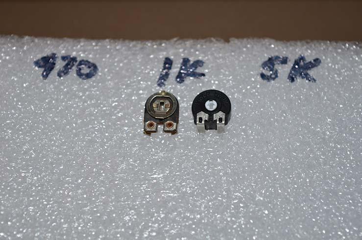
The markings on those Piher pots is difficult to read. One tip that I have is to place the components in a block of foam that is marked for the value.

I like to test all of the new components before I install them. After they are tested, I stick them in the foam. This makes the re-cap/re-pot procedure go faster. I’ve also found new parts that are technically “in spec”, but are so marginal that I wouldn’t want to use them.
I also mark and stick the old components in the foam when I remove them. This makes it easy to test the old components to get an idea of how well they have aged.
BTW, the adjustment for the signal strength is one that you could get away with adjusting without instruments. Tune between strong and weak stations and adjust until the display gives a behavior that you like.
Glitch
-
AuthorPosts
- You must be logged in to reply to this topic.