Forum Replies Created
-
AuthorPosts
-
 MadskpGOLD Member
If sound, operation and backlight of the panel are OK, then a BV10-32 has almost always a defective Pcb. 15 MEMC (Part 8005458) and not a defective Panel. This module is responsible for the image feed to the panel.
Ok, sounds like good. What would this mean in terms of reparability? I’m ignorant in that matter but I suppose any TV has a module that is responsible for the image feed to the panel. So would it be possible to replace the electronic from there? Dont know if I’m clear…
Looking at the servicemanual it seems like replacing this part is a matter of unscrewing the back panel of the tv, disconnect three cables, unscrew 6 screws and replace the PCB with another and put it all back together.
Without research my guess would be that getting the new part could be the hard part.
Of course the function of the backlight has to be confirmed before getting into this
Location: Denmark
MadskpGOLD MemberThe white gear wheel is just snapped on the axle. Either pull it or use a small needle to open the snap…
Succes. It just needed the right amount of force to come of. Thanks for the tip. Always great to know beforehand if use of force is a good idea or gonna break think.
Installation of the new laser module vent smooth and now the CD part of the BC9300 is running smooth again ?
Thanks to everyone for inputs
Next up is changing belts in the casette deck
Location: Denmark
MadskpGOLD MemberOne quick question: When you say 3rd Gen siri remote, do you mean the very latest version with the USB-C charging port (rather than the second generation with the lightning port?) Wiki says they are identical other than the charging port, but as we know there may be hidden SW changes! See wiki here: https://en.wikipedia.org/wiki/Siri_Remote (Looking at that wiki naming convention – we may need to rename the ‘2.gen’ siri remote in your picture as Gen 1.1 . They call the new shape (with Lightning) siri remote Gen 2)
Thanks for your input
Did not notice what connector type was on it, but will have to look at it next time I’am there, so it might as well be a 2. gen then. Also I will have to check the SW version.
I will dive into that naming convention and update the first post accordingly.
Location: Denmark
MadskpGOLD MemberAnd use ESD-protection! These things are highly sensitive to static electricity. Many owners experience that new lasers don’t work, – and while it is correct that many asian “counterfeits” won’t work, or only work for a few hours, many lasers are damaged by static electricity, – either during shipping, if shipped without shorting clamp and/or ESD-shielding or by handling without taking proper ESD-precautions. I have seen many of both cases. Martin
Hi Martin and thanks for the warning. I have a grounded antistatic mat and wristband ready so I hopefully won’t fry the new module in the proces
Location: Denmark
MadskpGOLD MemberHi: Watch this video
Go to 5:45 mark. DerekHi and thanks for the video link. It seems though that on the unit he is working on in the video he is removing a plastic bracket which gives acces to the other guide rail. But on the on from the BC9300 that both the guide rail and the overhanging “bracket” is part of cast metal, so there is no way to get the laser module up in that side of the mechanism.
As I see it the only way is to remove the white gear, but I am very open to other suggestions
Location: Denmark
MadskpGOLD MemberYesterday I was visiting my parents, and short before I had to leave I helped them force quit an app on their Apple TV 4K (3rd gen). They have never used the Siri remote as the control the ATV via PUC from their Beoplay V1. But in order to force quit the app I had to use the Siri remote.
First thing that happened when I touched the home button on the Siri remote was that the Beoplay V1 switched to source TV (their apple TV is on V.MEM). I tried again a couple of times and the same thing happened. When I covered the IR eye on the Siri remote this did not happen, so it seems that the IR control with B&O remote codes are back in the 3rd gen Siri remote.
Unfortunately I was in a hurry to get home, so didn’t have time to do more tests. I will do more testing the next time I visit them and in the meantime I hope that other members are able to use this. My guess is that the functionality is much the same as in the 1st gen siri remote as described in the first post in this thread and in the old post.
Location: Denmark
MadskpGOLD MemberHowever, this is only so, if the ‘3 black boxes’/the Beolink Passives have a SW 1.5 or higher. Please see Guy’s post in this thread: #14907
The solution with the 1611 converter should still work even if the Beolink Passives are SW 1.3 with the only exception being that the A.AUX command will not work.
All other audio and/or video commands listed on the diagram in Guy’s post in this thread should activate the Audio Aux Link port on the 1611 converter for Audio or video sound respectivly.
Location: Denmark
MadskpGOLD MemberIf you want to dig into it using an MCU I can recommend starting here. It supports IR and datalink so should be usable for PL data as well I guess. https://github.com/Arduino-IRremote/Arduino-IRremote/blob/master/src/ir_BangOlufsen.hpp#L4 In the end you don’t have to understand or reverse engineer the data protocol at all. Just record and replay what comes out of the W1 PL data pin. So any software that can record and send raw IR data will work. For the sending part just make sure to switch of any carrier frequency.
Thank you, I will try to dive in to that when I have some time on my hands. Always great to have a starting point to learn from.
Location: Denmark
MadskpGOLD MemberHello and thanks for the input.
I don’t have any experience with logic analyzers but might try to dip my to into it.This project might actually have a tool I can use (bullet number 3):
https://github.com/jensjoachim/B_and_O_Projects
It might take some time before I get to it as I have some other projects going at the moment and not much spare time.
thanks again for the input
Location: Denmark
MadskpGOLD MemberSlowly reverse engineering the Datalink protocol used between the BeoMaster / BeoCord / BeoGram 5500, for a secret project.

sounds very interesting. Looking forward to more info.
Are you avare of these two projects?:
https://github.com/jensjoachim/B_and_O_Projects
https://github.com/toresbe/datalink
Location: Denmark
MadskpGOLD MemberSo my guess is that to use the BM4500 as a slave unit it should be conencted to a Master unit via the AUX socket. However a normal Audio Aux cable can not be used as this will connect Audio in to Audio in and Audio out to Audio out. I have to make a crossed cable and do some more testing. update will follow
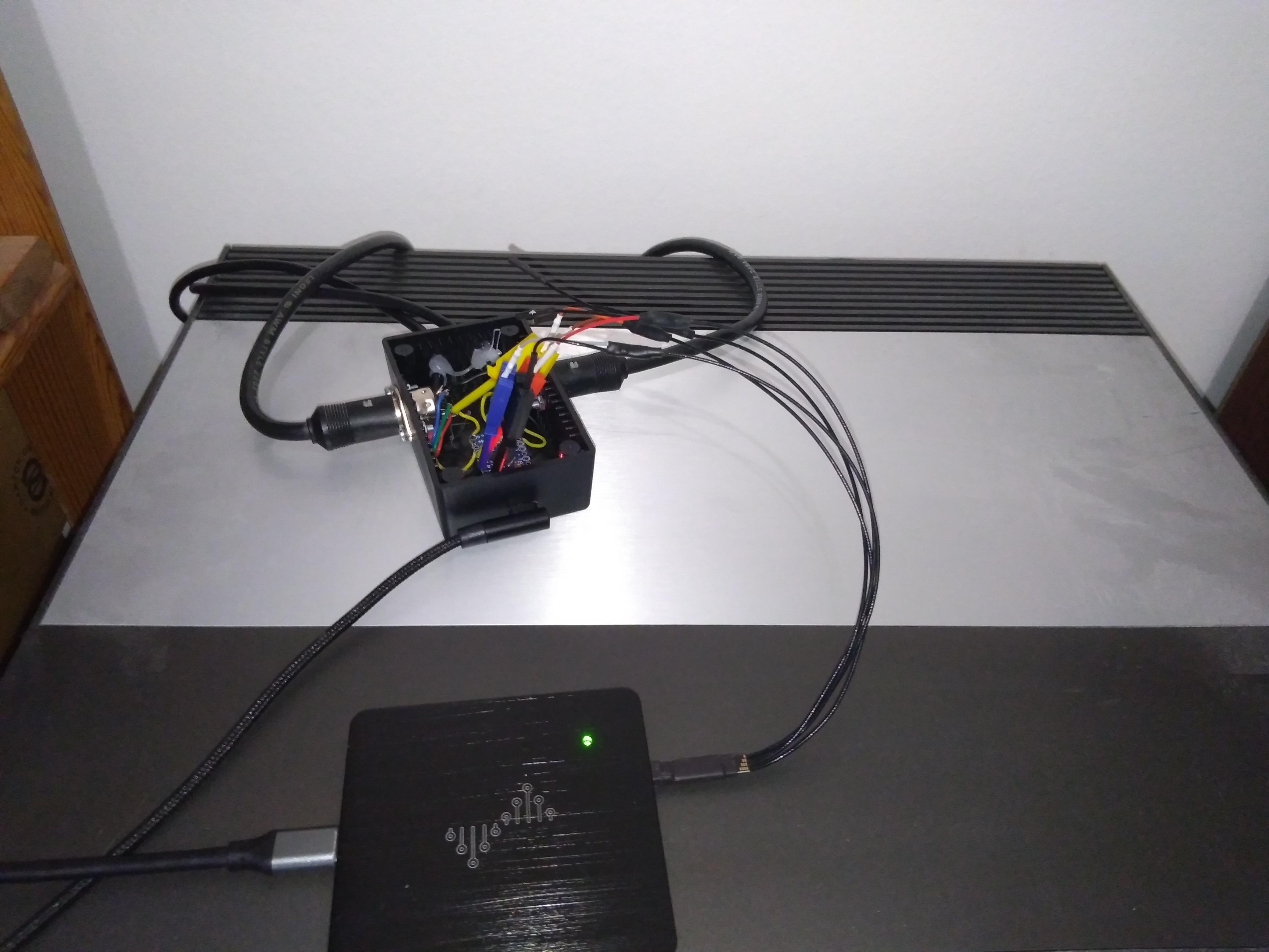
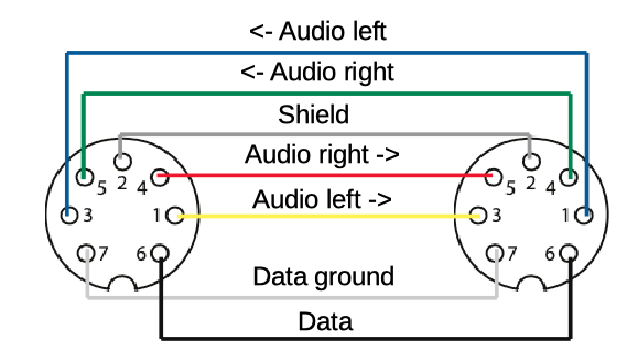
Finally got some time on my hands to make a Crossed Audio Aux cable to be able to test the BM4500 as a slave with another non Masterlink Beomaster.
The cable pinout looks like this:

The inputs and the output are switching places whereas the data and the ground pins all connects to the corrosponding pins on the other connector
I used a Beocenter 9300 as the Master unit (set to option 1) and the Beomaster 4500 as the slave unit (set to option 1.6).
A picture of the setup

And it works :-). I can control the radio channels on the BC9300 from the BM4500 when I use Link + commands.
Next up I wonder how it will work if MCL2 link rooms are connected to the speaker 2 connectors on the BM4500. I guess there must be some kind of limiting factor somewhere since B&O says that option 6 must no be used.
Location: Denmark
MadskpGOLD MemberJust to let you know a fellow Beoworlder offered to take over the project in exchange for some spare part to other projects, so I have choosen to focus my time on these instead of trying to revive this BM5500 myself.
But thank for the input
Location: Denmark
MadskpGOLD MemberYou may check the sw version of your BM. Talking about options 5 and 6, those were only available in earlier 1-way versions. 1-way function only had been included in the BM 4500 with a sw version below 2.1.
Thanks for responding. I was not aware that the BM4500 also had been in a one way version initially. Interesting.
Mine is labeled SW 1.6 on the back, and looking at old forum post I can see that when the 2 way communication was introduced in SW 2.1 the ability for the BM4500 to act as a ML slave was removed. Thus I’m pretty sure mine is a software 1.x even if it has had a software upgrade along the way.
This fits me fine as I have no 2 way remotes, and for my use case it could be great to have it act as a link room in the setup.
Jus to see that this function actually worked I connected it to a BS Ouverture via a Beolink 1611 converter. With the BM4500 in option 1.6 and the Ouverture in option 1 I cold start the sources on the BS Ouverture from the BM4500 with the use of link + Audio commands while both units would still use local sources with normal audio commands. Great 🙂
Location: Denmark
MadskpGOLD MemberI wonder how the BM4500 should be able to work as a slave in a MCL2 system connection wise as it does not have the MCL input as the MCL2AV has? It sees wierd to be mentioned in the manual if the product is not hardware wise ready for it.
A quick test to see what happens when using option 1.6 or 2.6.
When the BM4500 is in option 1.5 or 2.6 it will not react to Link + audio commands.
But when I set it to option 1.6 or 2.6 all Link + Audio commands activate AUX on the BM4500.
Further more the schematics in the service manuals show the data pins on the AUX socket and the speakerlink (MCL2) sockets are connected so all signals are passed between these two sockets.
So my guess is that to use the BM4500 as a slave unit it should be conencted to a Master unit via the AUX socket. However a normal Audio Aux cable can not be used as this will connect Audio in to Audio in and Audio out to Audio out.
I have to make a crossed cable and do some more testing. update will follow
Location: Denmark
MadskpGOLD MemberOk that makes sense. just being curious about the usecase for that connection
Location: Denmark
MadskpGOLD MemberGreat to hear that it is now working ?
I am wondering though why you would need this connection when the speakers are connected to the Beoport. This connections is not shown in the manual for the Beoport and the audio out port was originally blocked with a label from the factory
Location: Denmark
MadskpGOLD MemberHello
just for clarification, do you use the audio out minijack socket on the Beoport for this connection?
And also, do you not have speakers connected to the Beoport powerlink ports or headphone jack?
one simple test to try if you haven’t allready done that would be to connect another source to the line in socket on the PC just to check if something is different
Location: Denmark
MadskpGOLD MemberHello and welcome to the forum
The 1656 Beolink Passive should work just fine for your purpose. One important note is that you need a fully wired powerlink cable between the ouverture and the 1656 for it to work.
you might also be able to find the box named as ML-MCL converter with a different type number. It is the same box, it can just be used for other types of setups also. If an Ir eye is bundled with a ML-MCL converter you wont need that in your setup.
hope this is helpfull
Location: Denmark
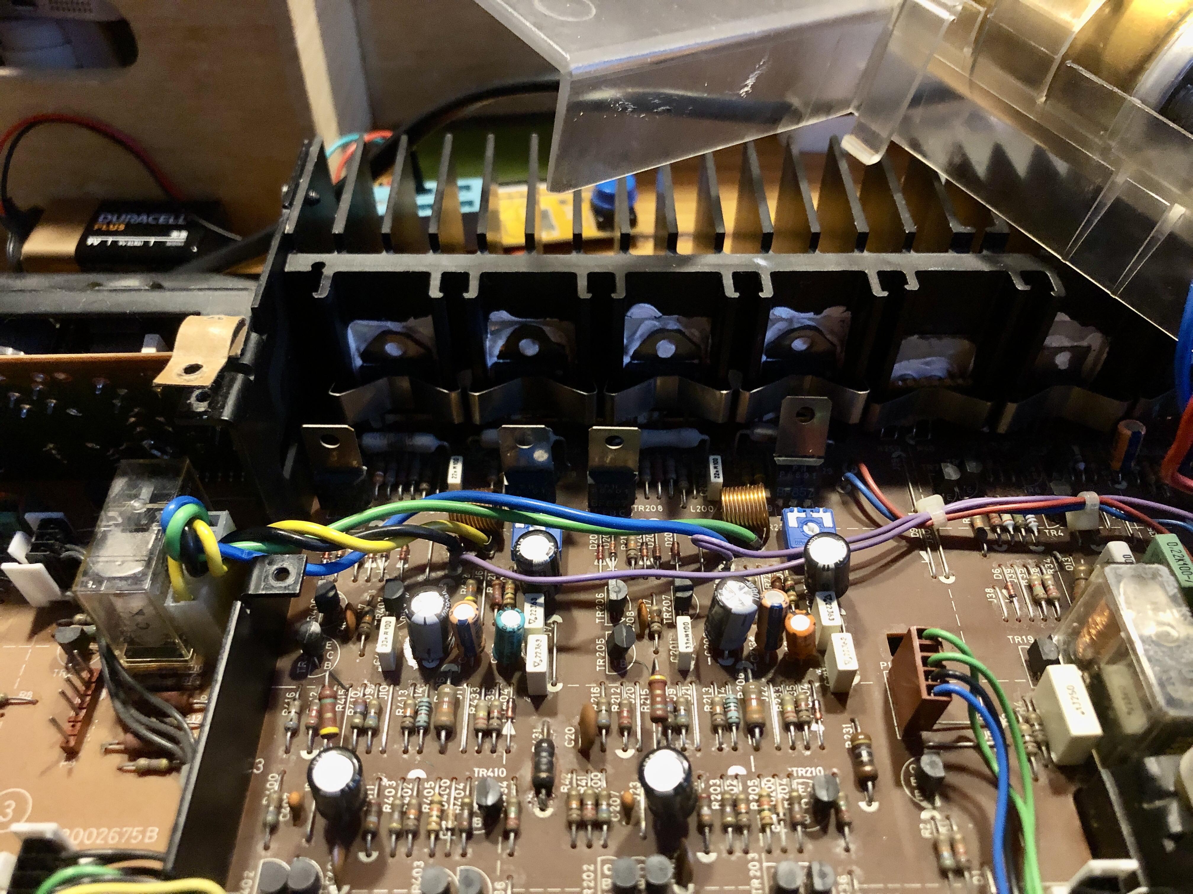
MadskpGOLD MemberOk so I removed R34, and the relay was not clicking when I turned it on.
what I probably didn’t notice after the last incident was that there was no light in the display anymore.
I could meassure 5V supply to the display board.
And then I looked away for 2 seconds and fireworks started in the back of the amplifier.
From what I can see two of the big grey resistors has burn marks
Unless anyone thinks this is fixable I think I will let this BM5500 rest in peace.
One side note. It is a prototype unit with Red labels that my father got when he worked at B&O. I have noticed that there are things that doesn’t line up with what the diagrams show. For example there is a transistor callled TR5 on the display board with connections to two LED’s. This is not shown in the digram
Location: Denmark
MadskpGOLD MemberHello and thanks for the input.
I haven’t touched it since I made the post, but will try to investegate further based on your advice and post my findings
Location: Denmark
-
AuthorPosts