


Home › Forums › Product Discussion & Questions › BeoMaster › BM5500 power supply defects
- This topic has 5 replies, 2 voices, and was last updated 2 years, 10 months ago by
 Madskp.
-
AuthorPosts
-
23 July 2023 at 07:02 #47800
 MadskpGOLD Member
I am starting a new thread here as the topic of my earlier thread https://forum.beoworld.org/forums/topic/beomaster-5500-source-selection/
might not cover what the problem is.
As mentioned in that other topic the BM5500 was unstable when sources was selected, and the display was flickering between sources and both of the relays made clicking noises.
I have checked all the caps in the PSU and all seems to be within specifications.
Going deeper I started to measure voltages in P14 and P15 to see if anything was not right.
At one point there was a spark and a burnt smell.
Looking more into i today I found that around 20mm of the GND trace between R40 and R44 was burnt away.
I scraped the remains away and placed a wire between the two points, just to be able to take some measures, knowing that the fault might still be there.
No light in the display at all.
My measures showed that 8V in P14 = 0V, -12V in P15 = 8.7V and 12V in P15 = 0V
Tried to measure some more voltages, and again a spark, but this time very clear around C2 and RL1 and TR19. C2 and TR19 checks out fine with a component tester.
The trace between D10 and R3 might also look to have some damage, but I measure continuity (my unit doesn’t have the fuse F2 installed)
Any advice on how to proceed without risking more sparks and burnt components?
Thanks in advance
Location: Denmark
30 August 2023 at 10:43 #47801Hello,
I’m a month late, but if you are still looking for advice,looks like IC 1 ( display driver ) is having trouble. It is also in charge of producing the control signal for RL1, the relay that switches power to the amplifier. I’d bet thats the relay you hear clicking, and that’s the cause of the burnt traces (each times it closes there is inrush current charging the large C6 / C7 capacitors)
I’d start by removing R34. That will prevent RL1 from closing, hence cutting power to the amplifier. That should avoid any more damages in that area.
Then, look for issues around IC1
Location: France
My B&O Icons:
 30 August 2023 at 14:19 #47802MadskpGOLD Member
Hello and thanks for the input.
I haven’t touched it since I made the post, but will try to investegate further based on your advice and post my findings
Location: Denmark
30 August 2023 at 19:35 #47803MadskpGOLD MemberOk so I removed R34, and the relay was not clicking when I turned it on.
what I probably didn’t notice after the last incident was that there was no light in the display anymore.
I could meassure 5V supply to the display board.
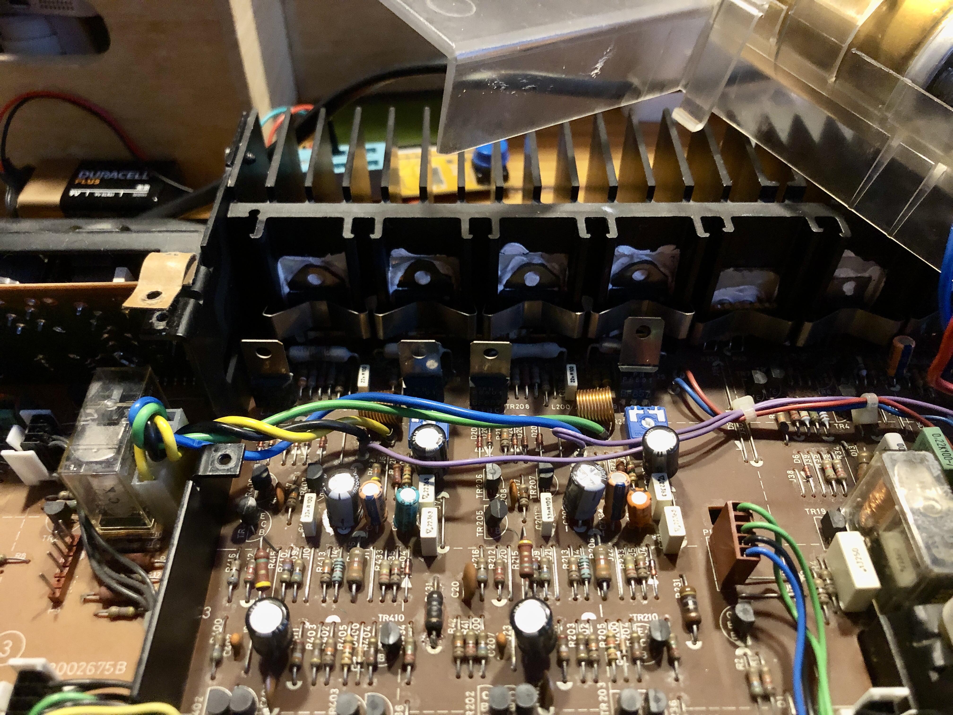
And then I looked away for 2 seconds and fireworks started in the back of the amplifier.
From what I can see two of the big grey resistors has burn marks

Unless anyone thinks this is fixable I think I will let this BM5500 rest in peace.
One side note. It is a prototype unit with Red labels that my father got when he worked at B&O. I have noticed that there are things that doesn’t line up with what the diagrams show. For example there is a transistor callled TR5 on the display board with connections to two LED’s. This is not shown in the digram
Location: Denmark
30 August 2023 at 22:08 #47804That one is on me, it seems I was mistaken in my previous message : RL1 has NC contacts, so disabling the relay just kept the amplifier powered. The relay needs to be energized to turn off the supply to the amplifier.
This could normally be done by shorting the collector and emitter pins of TR19, but it uses the same 8V supply as the display LEDs, and since those don’t work, we can not rely on that supply still operating, so let’s not do that.
It’s been a while since I worked on mine, I don’t remember if P23 can be unplugged ? If so, unplugging it will prevent any power going to the amplifier (for real this time). The downside is it will also disable the 50/60Hz signal going to the CPU, and I don’t know if this signal is only used for time keeping, or for other purposes.
Once you’ve done that, you should check that the display is operating normally.
Not having the proper schematics certainly won’t help, that’s for sure, but I don’t think there is any irreplaceable parts in those models except for the ROM and maybe the transformer, so it’s most definitely fixable.
Seeing how the magic smoke escaped from the amplifier area, you might simply have a shorted output transistor (and the blown power resistor of course).
Location: France
My B&O Icons:
18 September 2023 at 09:55 #47805MadskpGOLD MemberJust to let you know a fellow Beoworlder offered to take over the project in exchange for some spare part to other projects, so I have choosen to focus my time on these instead of trying to revive this BM5500 myself.
But thank for the input
Location: Denmark
-
AuthorPosts


- You must be logged in to reply to this topic.