Forum Replies Created
-
AuthorPosts
-
 MadskpGOLD Member
Hi. I did not receive a PM
Location: Denmark
MadskpGOLD MemberGood afternoon, I am trying to play music from my iPhone using my old Beolab 3500 speakers. I purchased a device from Bluetooth Solutions to interphase with my phone. I connected as instructed but the speaker remains dormant. I have tried Red-list, then go to Lopt and press 2 and 6 as those settings have been recommended in this website. Speaker does not respond. I was wondering if you can help me. I am attaching a picture. Thanks.
Hello. I don’t know this bluetooth Solutions product, but can you tell how it is connected to the Beolab 3500? Is it a DIN connector?
If so the MK1 and MK2 versions of the BL3500 has different pin assignments in the connector, so could be a cable issue. Please see one of the first pists in this thread to tell if you havd a MK1 or MK2 BL3500.
Next thing I wonder is if this product is supposed to activate the BL3500? Based on my findings in this thread I would not think so, but interesting if it does.
If it does not have this feature, and the connection is via the DIN connector the only way to activate the BL3500 is to use this key sequence on a BEO4 remote:
For BL3500 MK1: Menu + 0+ 4 + GO
For BL3500 MK12: Menu + Menu + 0+ 4 + GO
Note than when the speaker is activated with this sequence any keypress on the remote control will make it go to stand by. So volume control is done on the bluetooth part of it.
Hope this gets you further. You are welcome to make follow up questions
Location: Denmark
MadskpGOLD MemberOn a beo4 with joystick you can select ‘mode’. There are 3 modes. With your ‘mode’ setting pressing the ‘play’ button instead of the joystick should do the trick.
Yes of course. Thanks for reminding me. I Did not think that far when I was trying to use it, and had the other BEO4 near by.
Location: Denmark
MadskpGOLD MemberAn observation I did today was that my BL35000 MK1 would not react to the Menu + 0 + x + GO sequence from my Beo4 with joystick. I don’t know if the press on the Joystick sends a different command than GO on the older Beo4’s. But worth noting if a BL3500 do not react on a Beo4.
In my case I could just find a Beo4 with GO button and complete what I had to do
Location: Denmark
MadskpGOLD MemberHi Madskp, thanks for that! I will see to find an ML power box and share photographs of its content, just out of curiosity! Regards, Johan
It could be very interesting to see whats inside it
Location: Denmark
MadskpGOLD MemberI have now tried to a 1611 converter to the setup, so both the BLC NL/ML, BLC 1611 and BL3500.
Now the BL3500 says ML OK
The voltage on the Pink wire power + is 10.9V
The voltage on the blue vire power – is -10.9V
The voltage on the Green wire data + is 0.25V
The voltage on the green/white wire data – is -0.25V
So it seems that the BLC NL/ML does not have enough power to pull the voltages to the correct levels when a piece of ML equipment is connected.
So it might be that the options are:
- The ML power box
- A BLC 1611
- B3OHACK3R’s solution
- or a real ML audiomaster
Location: Denmark
MadskpGOLD MemberA little update from at testing session today.
I tried to connect the BLC to a BL3500 MK1 with a ML cable, and also connected the network link to my network.
On the BL3500 when I press Menu, 0, 2, GO it says No ML, so not registering it.
The voltages are also different when connected:
The pink Power + is now +4,68V
The Blue power – is now – 4,68V
Data + and Data – both are reading +0.4V which mean that at least the Data – can not pull the voltage to the correct level (-0.25V).
Also when I disconnect again and measure the data voltages they are both positive, and arround 0,3V. They might also both have been positive when I measured yesterday, so it could be that the missing negative data voltage is what the power box does?
Location: Denmark
MadskpGOLD MemberCould it be the BLC only fails to supply the POWER+
According to my measurements it does supply that.
What I noticed when I tried measuring again is that power + and – starts at a low voltage 3-5V when the BLC is booting, but then changes to the +10,8V and -10.8V when it is ready.
One thing I did not mention before is the blue/white wire for ML sense. That has no voltage, but should not be relevant to the BL2000. Also in the RJ45 ML cables it is connected to power+
If I can find the time in the weekend I will try to connect a BL3500 to see if I can make it do anything
Location: Denmark
MadskpGOLD MemberJust to see what the BLC supplies I took mine out and connected it to power and a ML cable with loose ends.
On the the data + and – lines I can meassure 0.2-0.3V and – 0.2-0.3V so I would say that might be 0.25V (when taking my shaking hands into account 😉 )
On the pink vire I measure 10.8V and on the blue wire -10.8 V
So the BLC seems to have all the voltages coming out of it.
Now I am really confused what the ML power box does?
Location: Denmark
MadskpGOLD MemberThe service manual describes a testing procedure for when the door does not close, or only slides down. In that case it says that if 3.3V is measured on pin 2 in the connector P1 when the door is in the lower position, the PCB with the magnetic switch should be replaced.
I do measure 3.3V even when it is not in that position, so might be an indication that something is wrong.
However the 6V that should also be in that connector, which I would guess is a supply is not there, so maybe something else is also wrong. I tried to measure for the 6V 2 PCB’s down, but still nothing.
I might have to start replacing the magnetic switch, provided I can finde. a replacement, and see what happens then
Location: Denmark
MadskpGOLD MemberHope someone else has been wondering about this also
I have been wondering about that powerbox indeed, and would very much like to know how much there is in it.
It migth be that it has to generate both the positive and the negative voltage to support the systems that need both.
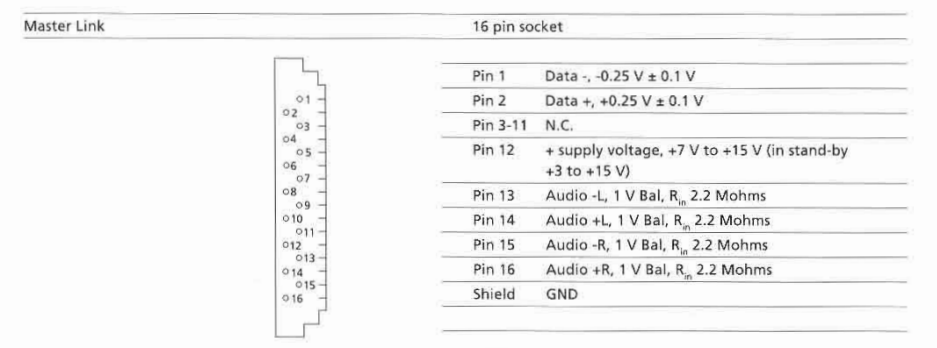
However the Beolab 2000 among others only has connections for the positive voltage according to the specifications in the servicemanual for it:

And on the diagram

So it might be that by supplying the postive voltage to pin 12 is enough.
In some of my testing with the BL3500 this was not enough for stand alone operation, but in this case where you also has the ML data signals from the BLC it might be that could be enough.
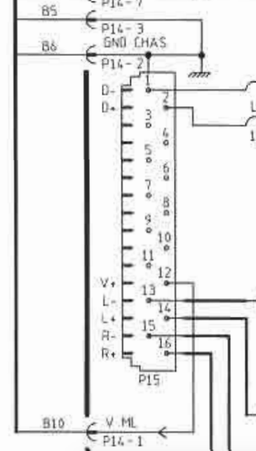
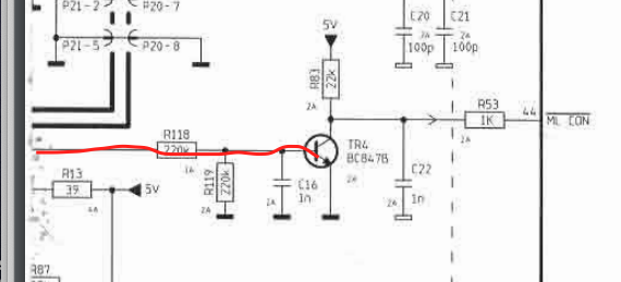
Looking at one of the other diagrams for the BL2000 I can see that the positive voltage fromt the ML connector is used to activate a transistor that activates a conenction called ML CON, which I assume is a way to tell the BL2000 that it is connected to ML.

I don’t know if it is this simple, but If you have some pieces of ML cables that are cut on the middle you could probably try to make an adapter.
I can also try some testing with a BL3500 but might not be before next week I have the time for it
Location: Denmark
MadskpGOLD MemberJust found this old thread about the ML Power box https://archivedforum2.beoworld.org/forums/p/16217/141383.aspx
There is especially on post that mention this:

Where the last part I have underlined with red might be a dealbreaker.
Location: Denmark
MadskpGOLD MemberOne extra piece of advice. The double sided tape that holds the glass plates may not have the propper strenght anymore.
Therefor there is a risk of the glass plates falling of when the top lid is open
Location: Denmark
MadskpGOLD MemberLooking very good ?
I went the cheap way for my RL45’s and bought an extra set to get on replacement strap.
Ironic the used equipment are sometimes cheaper than the spare parts for itLocation: Denmark
MadskpGOLD MemberGreat to hear you worked it out ?
Location: Denmark
MadskpGOLD Member2020 is the one with the Antenna port.
The other ones are without. The differences lies in which setup type the where bought for and if the had the IR eye or not. For your setup it should not matter
Location: Denmark
MadskpGOLD MemberI would not suspect anything else at this point.
Location: Denmark
MadskpGOLD MemberLovely Beocave!
Thanks ? though it is allready reorganised since the picture was taken to make space for more items ?
Location: Denmark
MadskpGOLD MemberI’ll also look into which capacitors I need to replace first for laser.
Unless you have good experience with mounting SMD caps I will recommend the Approach Guy have in the linked thread where he use standard capacitors instead. In my experience the SMD ones are not easy to solder on to the board with a soldering iron
Location: Denmark
MadskpGOLD MemberWhen you are going to replace it a piece of advise is to also disconnect the power for the Beosystem 4500 to avoid any risk of damage anything in the process
Location: Denmark
-
AuthorPosts