


Home › Forums › Product Discussion & Questions › BeoLab › BeoLink Converter 1611 Innovative Configurations
- This topic has 507 replies, 21 voices, and was last updated 2 months, 3 weeks ago by
 Madskp.
-
AuthorPosts
-
15 January 2023 at 15:25 #42334
 Moderator
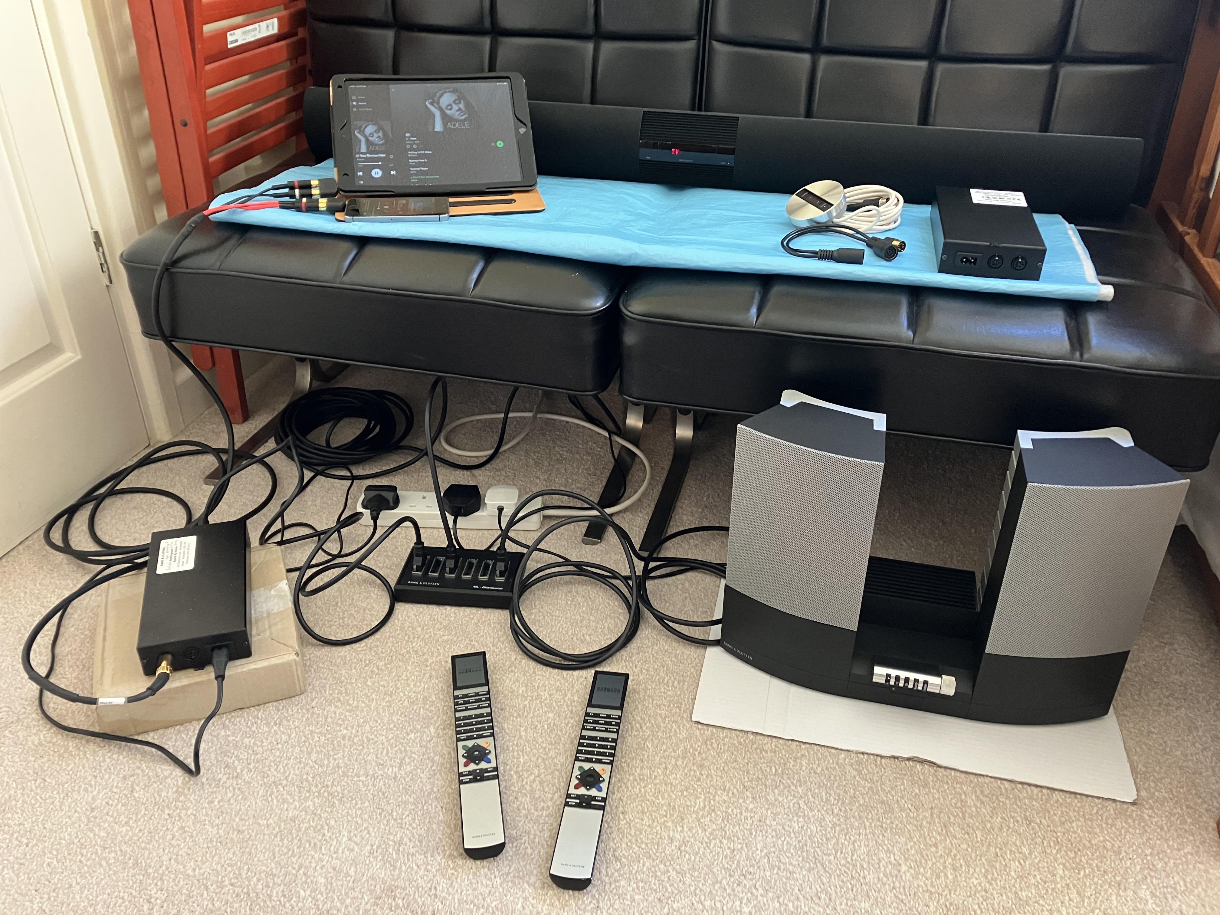
OK so Test 7 ongoing – I had to tidy my test setup!

- BL1611, BL2000 and BL3500 connected by ML
- To avoid putting BeoLabs in separate rooms, BL3500 is in L.OPT 4 and BL2000 is in L.OPT 6:
- Left Beo4 is in permanent LINK mode, to control BL3500
- Right Beo4 normal mode, to control BL2000
- BL1611 audio source is iPhone 5s
- BL1611 video source is iPad
It all works pretty much as I would expect to work with a ‘normal’ audiomaster. I can select video (iPad) or audio (iPhone) sources with both Beolabs, including the front panel on the BL2000. I am unable to have ‘video’ source on one Beolab with ‘audio’ source on the other – but I expected this because ML can only carry a single source in each direction.
Two observations:
- With both Beolabs playing a video (iPad) source, pressing PC (or A.AUX) on the BL3500 remote switches both Beolabs to the audio (iPhone) source. In the same situation, pressing PC (or A.AUX) on the BL2000 does nothing. This confirms the inability of my BL2000 to do anything with those two commands.
- If I change the source using the BL2000 remote, the source also changes on the BL3500 (as expected) but the display continues to show the original source. (It may well behave like this with a normal audiomaster.)
I will leave it running for a while in case anyone has anything further to suggest or test.
Location: Warwickshire, UK
My B&O Icons:
 15 January 2023 at 16:13 #42335
I have no intention of going anywhere near a Wireless 1
Unless SW 3.3 make the powerlink socket behave like we are used to…
Whilst a lot of people talk about the 8 pin din being a PowerLink socket we all know that is not really true. It just used the old MCL din socket so that a new module would not need to be designed.

Location: Hampshire, England
15 January 2023 at 16:15 #42336MadskpGOLD MemberI have no intention of going anywhere near a Wireless 1
Unless SW 3.3 make the powerlink socket behave like we are used to…
The text on the Beoworld product page regarding Beolink Wireless
suggest that the powelink socket in the BL3500 was first added after release of the Wireless 1 and that a special powerlink cable is needed
BeoLink Wireless 1 can be used with any pair of active loudspeakers except BeoLab 3500. BeoLab 3500 will later be updated to include a PowerLink socket to enable it to be compatible with BeoLink Wireless 1. It will not be possible to upgrade any existing BeoLab 3500 loudspeakers to include this new connection.
To ensure that the control data can pass as well as the sound signals the loudspeakers must be connected using a fully-mounted 3.5mm PowerLink cable. Only BeoLab 5 loudspeakers are supplied with this cable so users should order required cables.
Location: Denmark
15 January 2023 at 16:31 #42337MadskpGOLD MemberOn the other hand i may just be a fully mounted powerlink cable, which was not common anymore at the release of the wireless 1.
Location: Denmark
15 January 2023 at 16:33 #42338OK so Test 7 ongoing – I had to tidy my test setup!
So cute, you didnt vacuum today but you still protected the carpet under the converter and the 2000! 😀
Location: Paris France
15 January 2023 at 16:48 #42339Quick report on Test 8: PL trigger of BL1611
Part A, BL2000:
So I rigged up a 3v source (2x 1.5V cells). I then tested this with BL2000 (in L.OPT 6), injecting the voltage between pins 4 (+) and 2 of the BL1611’s PL socket with the usual two audio sources connected to AAL.
With the BL2000 powered down, applying 3v does nothing. The BL2000 does not switch on.
If playing an audio source, this is unaffected by voltage application.
If playing a video source, with voltage application the BL2000 switches to an audio source.
Having injected and then removed the voltage to the BL1611, it remains ‘audio source only’. I cannot then get a video source on the BL2000 with either the remote or the front panel. It stays like this until I disconnect the mains power to the BL1611, wait a few seconds (EDIT: minimum 10 seconds), re-connect mains power and wait a few seconds more. It then returns to normal dual input behaviour.
Hence the PL trigger voltage seems to force BL1611 into audio mode which is only then cleared with a power cycle.
Again, any suggestions for further testing are welcome whilst I repeat the above with BL3500.
EDIT 2: I repeated the above with the BL2000 in L.OPT 0. No change to behaviour. I see no merit in trying L.OPTs 4 or 5.
Location: Warwickshire, UK
My B&O Icons:
15 January 2023 at 16:50 #42340So cute, you didnt vacuum today but you still protected the carpet under the converter and the 2000!
Hey, I am in a rental house and who knows what may burst into flames ?. The cardboard will protect the carpet!
Location: Warwickshire, UK
My B&O Icons:
15 January 2023 at 17:07 #42341Further report on Test 8: PL trigger of BL1611
Part B, BL3500:
BL3500 behaves exactly as BL2000 above. The only ‘funny’ is that when the PL voltage forces a switch from video to audio, the BL3500 display continues showing the original video source.
Note that the BL1611 does require at least 10 seconds of ‘power off’ to clear the audio-only mode. It then takes about another 10 seconds to re-configure when the power is re-connected.
Location: Warwickshire, UK
My B&O Icons:
15 January 2023 at 17:21 #42342Whilst a lot of people talk about the 8 pin din being a PowerLink socket we all know that is not really true. It just used the old MCL din socket so that a new module would not need to be designed.
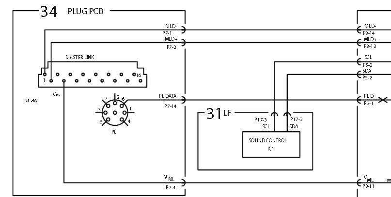
I may be missing something, but that diagram shows pins 6 and 7 transposed with pins 4 and 5. Is that a typo?
Location: Warwickshire, UK
My B&O Icons:
15 January 2023 at 17:39 #42343I am stopping the tests for today. Some may have noticed that I have deliberately avoided anything that involves soldering, but I will be forced to make up a few leads to try most other options!
I am happy to repeat anything that I have tried so far if you want more info or there is something that I have missed.
Attached is a fresh copy of the test schedule with new notes in Blue.
Location: Warwickshire, UK
My B&O Icons:
15 January 2023 at 17:52 #42344MadskpGOLD MemberWhilst a lot of people talk about the 8 pin din being a PowerLink socket we all know that is not really true. It just used the old MCL din socket so that a new module would not need to be designed.
I may be missing something, but that diagram shows pins 6 and 7 transposed with pins 4 and 5. Is that a typo?
to me it seems more like pin 2 is placed in the opposite end of the connector than it should be. But as it only is a block diagram and not a full one it might be a typo
Location: Denmark
15 January 2023 at 19:26 #42345Whilst a lot of people talk about the 8 pin din being a PowerLink socket we all know that is not really true. It just used the old MCL din socket so that a new module would not need to be designed.
I don’t understand.
Apparently, MCL Beolabs can be started with a 5V trigger voltage. MK2 (or beyond a certain SW can’t). But it is often mentioned that the DIN socket was changed from MCL to Powerlink to comply with Beolink Wireless 1, even if the BLW1 guide say it must be connected through ML and not PL.
So the question is what is this socket, what was it along the evolution of the speaker and what is it for?
Please note that this is just out of curiosity since I now know that the 3500 will never be as better as with a 1611 to drive it!
Location: Paris France
15 January 2023 at 19:33 #42346MadskpGOLD MemberQuick report on Test 8: PL trigger of BL1611 Part A, BL2000: So I rigged up a 3v source (2x 1.5V cells). I then tested this with BL2000 (in L.OPT 6), injecting the voltage between pins 4 (+) and 2 of the BL1611’s PL socket with the usual two audio sources connected to AAL. With the BL2000 powered down, applying 3v does nothing. The BL2000 does not switch on. If playing an audio source, this is unaffected by voltage application. If playing a video source, with voltage application the BL2000 switches to an audio source. Having injected and then removed the voltage to the BL1611, it remains ‘audio source only’. I cannot then get a video source on the BL2000 with either the remote or the front panel. It stays like this until I disconnect the mains power to the BL1611, wait a few seconds (EDIT: minimum 10 seconds), re-connect mains power and wait a few seconds more. It then returns to normal dual input behaviour. Hence the PL trigger voltage seems to force BL1611 into audio mode which is only then cleared with a power cycle. Again, any suggestions for further testing are welcome whilst I repeat the above with BL3500. EDIT 2: I repeated the above with the BL2000 in L.OPT 0. No change to behaviour. I see no merit in trying L.OPTs 4 or 5.
Just a note. In my experiment I injected the power on pin 4 and 7, but as mentioned pin 2 and 7 is soldered together in my 1611, and conneted to the ground plane in the 1611. As you see some kind of reaction Im not sure if it will make any difference in your case. But if you have a multimeter handy you could try to measure if pin 2 is connected to the ground i one of the connectors just to verify.
Then again it might not be a thing with the BL2000 and BL3500 as they in all official use cases has to be turned on in the link room.
Location: Denmark
15 January 2023 at 19:33 #42347the PL trigger voltage seems to force BL1611 into audio mode.
Seems logical since this is why a powerlink was fitted to the converter, to “tell” the masterlink source, audio was started localy from the AAL side.
which is only then cleared with a power cycle.
This is less logical. Or maybe not: the converter was meant to be connected to a Video AAL or Audio AAL, but not both at the same time. Then without Y splitting adapter or similar in which scenario would the converter need to revert to video mode after have been triggered by Powerlink?
Location: Paris France
15 January 2023 at 19:40 #42348MadskpGOLD MemberWhilst a lot of people talk about the 8 pin din being a PowerLink socket we all know that is not really true. It just used the old MCL din socket so that a new module would not need to be designed.
I don’t understand. Apparently, MCL Beolabs can be started with a 5V trigger voltage. MK2 (or beyond a certain SW can’t). But it is often mentioned that the DIN socket was changed from MCL to Powerlink to comply with Beolink Wireless 1, even if the BLW1 guide say it must be connected through ML and not PL. So the question is what is this socket, what was it along the evolution of the speaker and what is it for? Please note that this is just out of curiosity since I now know that the 3500 will never be as better as with a 1611 to drive it!
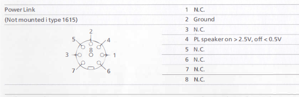
I dont undestand it either. The MCL pinouts on the Beotech page has a DC supply of 7.5-8.5 Volt on pin 2 where powerlink on/off pins can be either pin 1 or 4. Furthermore MCL normally caries speaker level signals, where powerlink caries line level signals.
Im confused
Location: Denmark
15 January 2023 at 20:30 #42349Just a note. In my experiment I injected the power on pin 4 and 7, but as mentioned pin 2 and 7 is soldered together in my 1611, and conneted to the ground plane in the 1611. As you see some kind of reaction Im not sure if it will make any difference in your case. But if you have a multimeter handy you could try to measure if pin 2 is connected to the ground i one of the connectors just to verify.
We now have a copy of the BL1611 Service Manual (I’ll PM you a copy) – here’s the PL socket:

I just opened my BL1611 up again to check internally with my multimeter – there is no continuity between pin 7 and anything else as far as I can tell. Pin 2 has continuity with the ground plane.
Location: Warwickshire, UK
My B&O Icons:
15 January 2023 at 21:03 #42350I dont undestand it either. The MCL pinouts on the Beotech page has a DC supply of 7.5-8.5 Volt on pin 2 where powerlink on/off pins can be either pin 1 or 4. Furthermore MCL normally caries speaker level signals, where powerlink caries line level signals.
I suppose that in MCL mode the BL3500 (LCS9000) worked a bit like an MCL2AV. That too used the speaker level input and turned it into a volume controlled PL output. The MCL2AV also had its own power supply, hence didn’t need the 7.5-8.5v supply. I suspect that (like the MCL2AV) the ‘MCL BL3500’ volume would also go up and down slightly as the ‘master volume’ in the audiomaster was varied.
Location: Warwickshire, UK
My B&O Icons:
15 January 2023 at 21:32 #42351This is less logical. Or maybe not: the converter was meant to be connected to a Video AAL or Audio AAL, but not both at the same time. Then without Y splitting adapter or similar in which scenario would the converter need to revert to video mode after have been triggered by Powerlink?
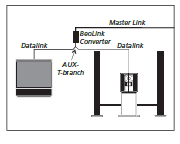
It could be connected to both video and audio AAL at the same time, hence this diagram in the ML handbook.

But I can’t work out how it triggered a return to videomaster. Perhaps something in the data triggers the switch back. I have just tried shorting the PL pin 4 to ground, but that makes no difference.
EDIT: Actually it must be a request over masterlink that triggers the switching between audio and videomaster, in the same way that we are using it with the Beolabs.
Location: Warwickshire, UK
My B&O Icons:
15 January 2023 at 22:06 #42352It could be connected to both video and audio AAL at the same time, hence this diagram in the ML handbook.
Of course idiot me. I forget it even if it was this diagram that started the dual input trick.
Location: Paris France
16 January 2023 at 06:39 #42354MadskpGOLD MemberSo tonight I made an attempt at Test 12 – making use of the BL1611 AAL pin 6 datalink input. I don’t have any pure datalink source devices other than my BG6500 turntable and that is packed away so carefully that I am not prepared to get it out for this project! However, I do have a DVD1 for which I previously made a special SCART to 7-pin DIN cable for the project described here: https://archivedforum2.beoworld.org/forums/p/45162/327485.aspx#327485 Basically, the cable connects SCART data pin 8 to DIN pin 6, plus audio to DIN pins 3 and 5. It previously worked well to connect an extra ‘CD’ player (the DVD1) directly to my BC9500’s AUX/TV socket, which also uses pin 6 for data. Anyway, for this test I used the BL3500 as the controlling ML device and the DVD1 was connected to the BL1611’s AAL socket. Audio (a CD) played fine with a video source connected, but no datalink control of the DVD1 was possible (I couldn’t start up the DVD1, play, stop, or change tracks with the remote, hence had to use the DVD1’s front panel). However, when I tried a long-press of the Beo4’s ‘off’ button, the entire system did shut down including the DVD1. Hence some data is being passed from BL3500 to the DVD1 via the BL1611, but just not the full spectrum of normal datalink commands. I hope that Test 15 (Control of OneRemote radio) will be more successful, once I have made that (nameless) adaptor!
sounds more or less as the experience I had with the BV6, 1611 and Beocord 3500. Didnt try the long press off though. Will test that for my next testing session
Location: Denmark
-
AuthorPosts


- You must be logged in to reply to this topic.