Forum Replies Created
-
AuthorPosts
-
 BRONZE Member
I have:
- BeoLab 4000 – 2x
- BeoLab 6000 – 4x
- BeoLab 8000 – 6x
- BeoVox 600 -2x
- BeoVox 1200 – 2x
- Grundig AudioRama 7000 – 2x
They are positioned throughout my house, so I use all of them.
My daughter will get the BeoVox 1200 set.
I also used to have a pair of S80 with a damaged coil on the mid tone driver. But after repair and restoration I gave them to my son.
(B&O throughout the family!)Location: The Netherlands
Favourite Product: BeoSound 9000
My B&O Icons:
 20 December 2022 at 12:22 in reply to: BeoLab 8000: 5-pin cable from RCA-PCB to LED-PCB sensitive #39862
Thanks @ Die_Bogener, for your recommendations.
What I did next:
I swapped the PCB01 TRAFO board from a working BeoLab 8000, into the troubling unit. I kept the other unit the same (PCB02 Power Supply & Amplifier board).Result:
- No issues with Auto stand-by, just smoothly switching from ON to OFF/Stand-by when it should.
- When the BeoLab with this (swapped) Trafo board is on, there is also no noise/buzz.
- When I touch the 5-pin cable when the BeoLab is ON, there is some noise/buzz.
- When I touch the 5-pin cable when the BeoLab is OFF, it does not cause the BeoLab to switch to ON.
Conclusion:
The amplifier seems to be fine. But the Trafo board/PCB 01 must be having the problem.
Question:
Since the voltage measurement (see earlier post) on the T2 trafo shows a non-symmetric load (20 Volt vs 23 Volt):
- Is the T2 trafo the problem source, or could it still be some other part or component on PCB01?
- If T2 has to be replaced, what is a good source to find a (reliable & affordable) replacement?
Location: The Netherlands
Favourite Product: BeoSound 9000
My B&O Icons:
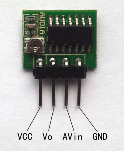
In the meantime I found this circuit. This seems to be a audio signal monitor that can push a trigger signal to switch an amplifier from standby to on.
Does anyone have experience with this?

Power supply voltage: DC 3V-15V
Standby current: 3V — — 0.7mA, 5V — — 1.2mA, 12V——3.3mA
Output:
- AUD1A: output high level 3mA or low level 3mA. A high level is detected after the effective signal is detected.
- AUD1B: output high level 1500mA or open circuit state. A high level is detected after the effective signal is detected. The output terminal has protective diodes, which can be directly connected to various loads (including inductive load).
Sensitivity: Audio or video signals with an amplitude not less than 180 mVp-p can trigger work effectively (the actual video signals are all 2V-2.5v).
Pin configuration:
- VCC— — power supply positive electrode
- Vo— — output terminal
- AVin— — AV signal input terminal
- GND— — power supply negative pole
The potentiometer in the lower left corner of the module is used to adjust the delay time, and the clockwise adjustment time is extended.
Be careful: Even if there is no audio/video trigger signal, the circuit will output a high-level pulse signal at the moment of power-on, and then enter the normal working state.
Productinfo and descriptions can be found here.
Location: The Netherlands
Favourite Product: BeoSound 9000
My B&O Icons:
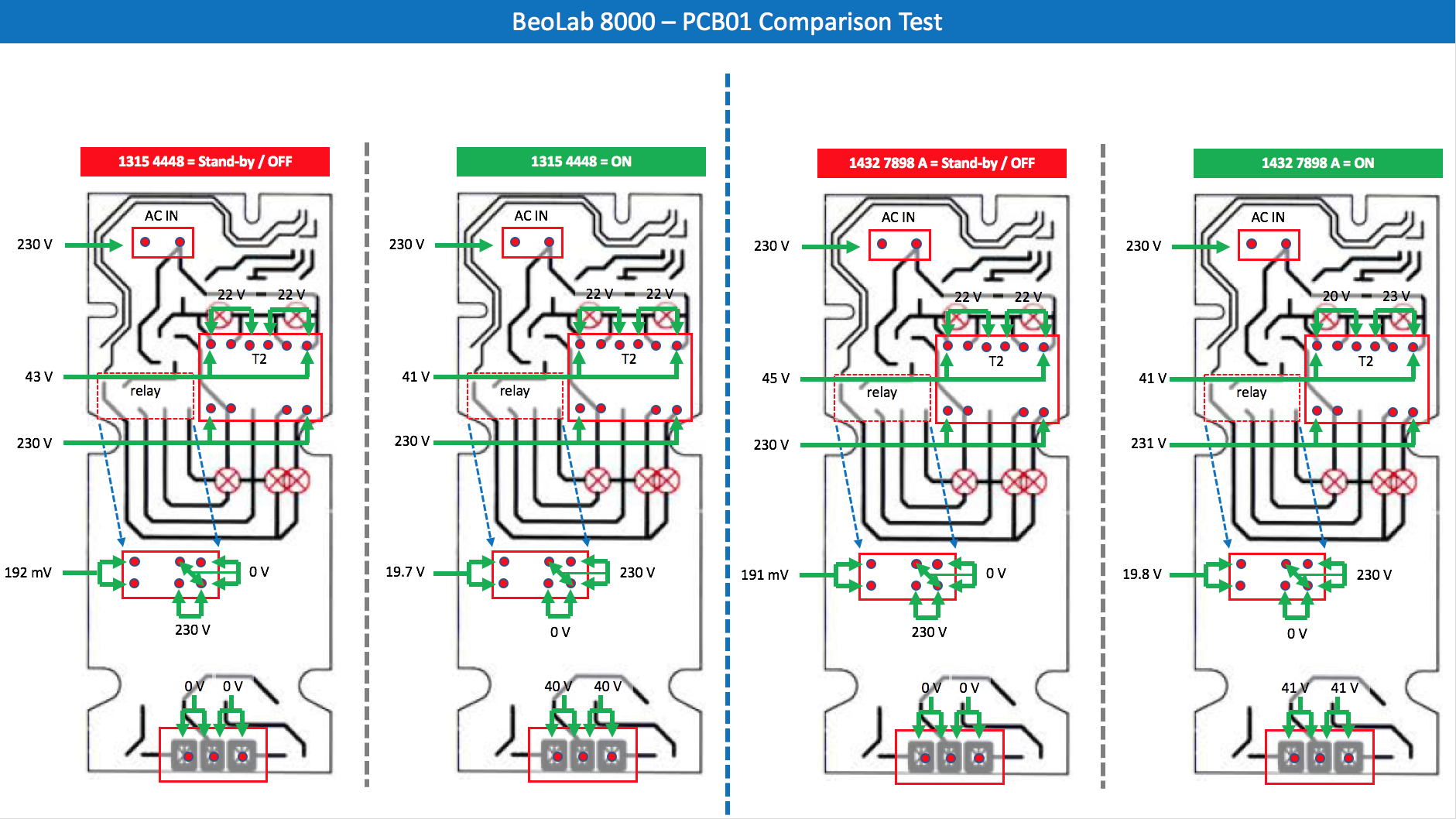
17 December 2022 at 12:04 in reply to: BeoLab 8000: 5-pin cable from RCA-PCB to LED-PCB sensitive #39860I have now been able to do some measurements on PCB 01. I did the same on another PCB 01 from a different well functioning BeoLab 8000, and put them side by side. It looks like this:
On the left side of the blue dotted line, the well functioning BeoLab 8000:
- Left/red = measurements in stand-by/Off mode.
- Right/green = measurements in On mode.
On the right side of the blue dotted line, the BeoLab 8000 with issues:
- Left/red = measurements in stand-by/Off mode.
- Right/green = measurements in On mode.

So compared, what I see:
- T2 shows 20 and 23 V, so not even.
- Else, I see no differences.
Question
Is there anything that we can conclude from this, that helps towards a solution?
Location: The Netherlands
Favourite Product: BeoSound 9000
My B&O Icons:
Thnx Guy!
Do you have a link to an example of the Playmaker?
By the way, do you know of any DIY kits, or boards that I could use for self-build integrations?
Location: The Netherlands
Favourite Product: BeoSound 9000
My B&O Icons:
Sounds Heavenly’s products are great, no doubt.
But (in this case) I am especially looking for something that works automatically: sound coming in, speaker switched on.
Location: The Netherlands
Favourite Product: BeoSound 9000
My B&O Icons:
Thnx @trackbeo
Ok, let’s check if I understood correctly what you mentioned. This is what I took from it:
- So as soon as there is 5 volt on pin 4 of the Powerlink connector, the amplifier will switch from OFF to ON.
- As long as one wants to listen to music, the 5 volt power (to pin 4) should remain active.
- In this setup there is no automatic ON/OFF switching of the amplifier. The amplifier switches ON when the 5 volt power source (connected to pin 4) is put ON. And the amplifier will switch OFF when the 5 volt power source (connected to pin 4) is put OFF.
Question
- Are my points above correct?
- If they are, how can I create a setup that automatically switches ON & OFF via a Powerlink input, when the audio source is non-B&O?
Location: The Netherlands
Favourite Product: BeoSound 9000
My B&O Icons:
Many thanks @Guy, @Mr10Percent and @Steve at Sounds Heavenly !
Very helpfull information.Just for my understanding …
Is it a matter of:
- The PowerLink connector gets 5v continuously, and an incoming audio signal is the trigger
- The PowerLink connector gets 5v as a short trigger (e.g. fraction of a second), caused by incoming audio.
I try to understand how the trigger function works.
E.g. If one takes the BeoLab 8000 and connects via the RCA input, the trigger is the audio signal coming in via the RCA.Location: The Netherlands
Favourite Product: BeoSound 9000
My B&O Icons:
6 December 2022 at 16:01 in reply to: BeoLab 8000: 5-pin cable from RCA-PCB to LED-PCB sensitive #39858New checks & tests
I have just swapped the PCB01 TRAFO board from a working BeoLab 8000, into the troubling unit. I kept the other unit the same (PCB02 Power Supply & Amplifier board).
Result: no issues with Auto stand-by, just smoothly switching from ON to OFF/Stand-by when it should. Also no noise/buzz.
So something must be wrong on PCB01 the Trafo board.
Location: The Netherlands
Favourite Product: BeoSound 9000
My B&O Icons:
OK, at least you now know how to search.
Location: The Netherlands
Favourite Product: BeoSound 9000
My B&O Icons:
Hi @Frog
Maybe the info in this thread helps:
https://beoworld.org/forums/search/MLGW/
By the way, searching is quite easy. If you click on “Forums” in the main menu of Beoworld, you will see the search field.

Location: The Netherlands
Favourite Product: BeoSound 9000
My B&O Icons:
1 December 2022 at 10:14 in reply to: BeoLab 8000: 5-pin cable from RCA-PCB to LED-PCB sensitive #39857Thnx Die_Bogener!
The issue of Auto stand-by clicking On-Off-On all the time, even happens when having no audio source connected to PL or RCA/Line in.
What about that ?
Location: The Netherlands
Favourite Product: BeoSound 9000
My B&O Icons:
@Matador: thanks for sharing the leaflet!
@Geoffmartin: check.Location: The Netherlands
Favourite Product: BeoSound 9000
My B&O Icons:
Thanks @Matador!
Very interesting document. Thanks for sharing.
Location: The Netherlands
Favourite Product: BeoSound 9000
My B&O Icons:
Very interesting @geoffmartin!
Great that you respond to this topic, as you have a lot of access to things. So very much appreciated that you like to share.
Is it possible that you share some pictures of what you describe as white and black sleeve versions?
PS.
Is this the Technical Sound Guide you are referring to?Location: The Netherlands
Favourite Product: BeoSound 9000
My B&O Icons:
Interested to know more about what this is.
Is it a record, what is on it?
Location: The Netherlands
Favourite Product: BeoSound 9000
My B&O Icons:
10 November 2022 at 18:01 in reply to: BeoLab 8000: 5-pin cable from RCA-PCB to LED-PCB sensitive #39855Thanks a lot Die_Bogener !
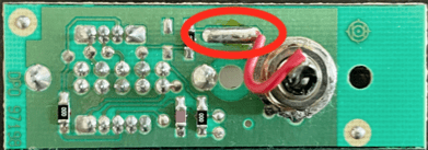
I now also noticed following. I touched the solder connection of the Left/Right signal wire (see red circle), with a screw driver. And immediately, the power switches ON. And when it is on, the hum/buzz gets stronger. Same happens (obviously) when I touch the back of the RCA connector (as it is the same connection of course). This does not happen when I touch the GND connection.

Concerning your advise to test by measuring (before plugging in the RCA):
- The voltage between source and 8000, both AC and DC
- Measure ground to ground
- And signal to signal
Just to be sure, do you mean …
- Ground & Signal at the RCA connector on PCB 05, at one side?
- And Ground & Signal at the P4 connector Amp PCB, as the other side?
Location: The Netherlands
Favourite Product: BeoSound 9000
My B&O Icons:
That’s a real nice model. To be honest I did not recognize it first hand, but after a bit of searching I found it.
It’s the BeoLit Teena 609 AM, from 1962. AM only, battery powered, plastic casing, available in 4 colors.
Reference links:
- https://beocentral.com/beolitteena609am
- https://www.radiomuseum.org/r/bang_beolit_teena_609_am_exp_iii.html
BeoLit Teena 609 with FM: https://www.radiomuseum.org/r/bang_beolit_teena_609.html
Location: The Netherlands
Favourite Product: BeoSound 9000
My B&O Icons:
4 November 2022 at 13:02 in reply to: BeoLab 8000: 5-pin cable from RCA-PCB to LED-PCB sensitive #39853Here’s another update. I made several other checks.
(Check 1) PCB 05 exchanged – I took the ‘PCB 05 Link shift board’ from another BeoLab 8000 and put it in the ‘trouble BeoLab 8000’.
(1) Result – Nothing changed. So, when nothing is connected to the RCA input on PCB 05: still a loud Hum. When an iPhone is connected to the RCA input, the hum is gone, Auto stand-by goes to OFF, but it also goes back ON again when I touch the 5-pin cable P4 on PCB 05.
So I conclude that the problem is not in PCB 05.
Observation: I noticed that when I touched the 3-pin JST cable from PCB 06 to the Amp, the Auto stand-by also switches to on. Same as when touching the 5-pin cable on P4 of PCB 05.
(Check 2) 3-pin JST cable changed – I hand-made another 3-pin JST cable to check if the original cable is the issue. This is to check if there is something wrong with the original cable between PCB 06 and the Amp.
(2) Result – When powering on, a slight hum/noise can be heard. Though it seems to be a higher pitch than before. Unfortunately, this hum/noise seems a bit to strong as the Auto stand-by does not switch OFF.
Observation: In the situation with the hand-made 3-pin JST cable, I noticed that when touching this cable or the 5-pin cable on P4 of PCB 05, nothing happens. Though, the BeoLab does not switch OFF.
Location: The Netherlands
Favourite Product: BeoSound 9000
My B&O Icons:
I am not sure as I have never setup such system with new BeoLab’s. Nevertheless, maybe some questions and suggestions to think over.
- Did this setup work before (showroom/pre-owner), or is this a first install?
- Did you try to reset the BeoLab’s to factory standard?
- Did you try to reinstall or update the speaker firmware?
- Did you try to change the order in which you connect and pair the speakers?
- Did you remove the B&O configuration App from your smartphone, and than reinstall it again?
Location: The Netherlands
Favourite Product: BeoSound 9000
My B&O Icons:
-
AuthorPosts