Forum Replies Created
-
AuthorPosts
-
 Moderator
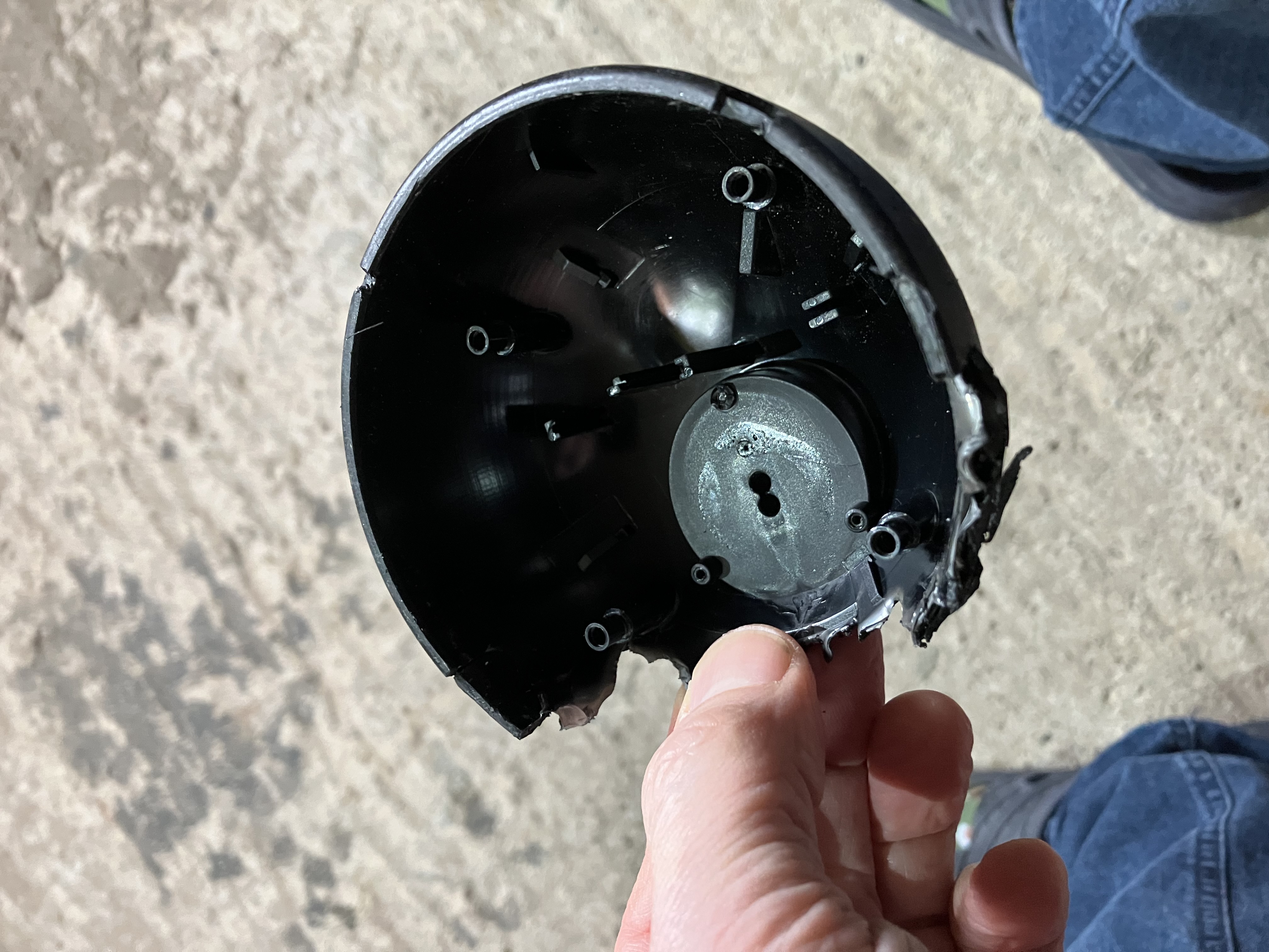
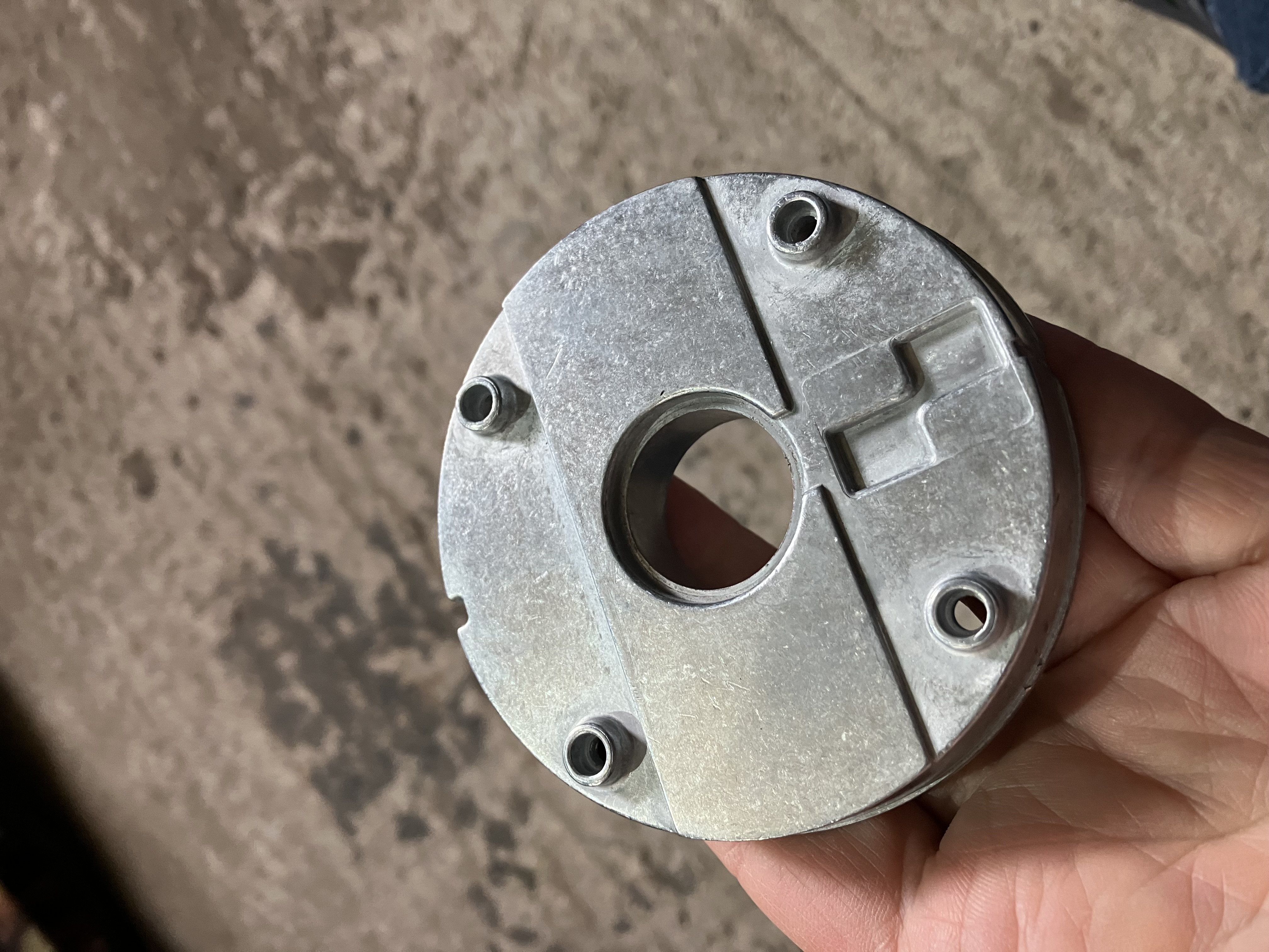
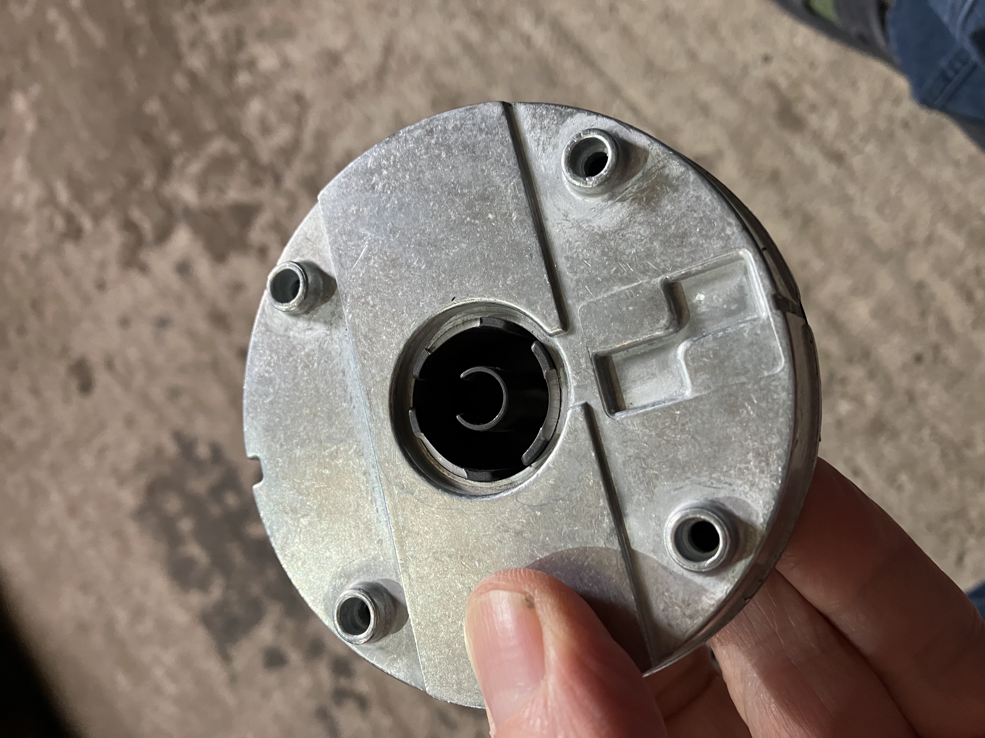
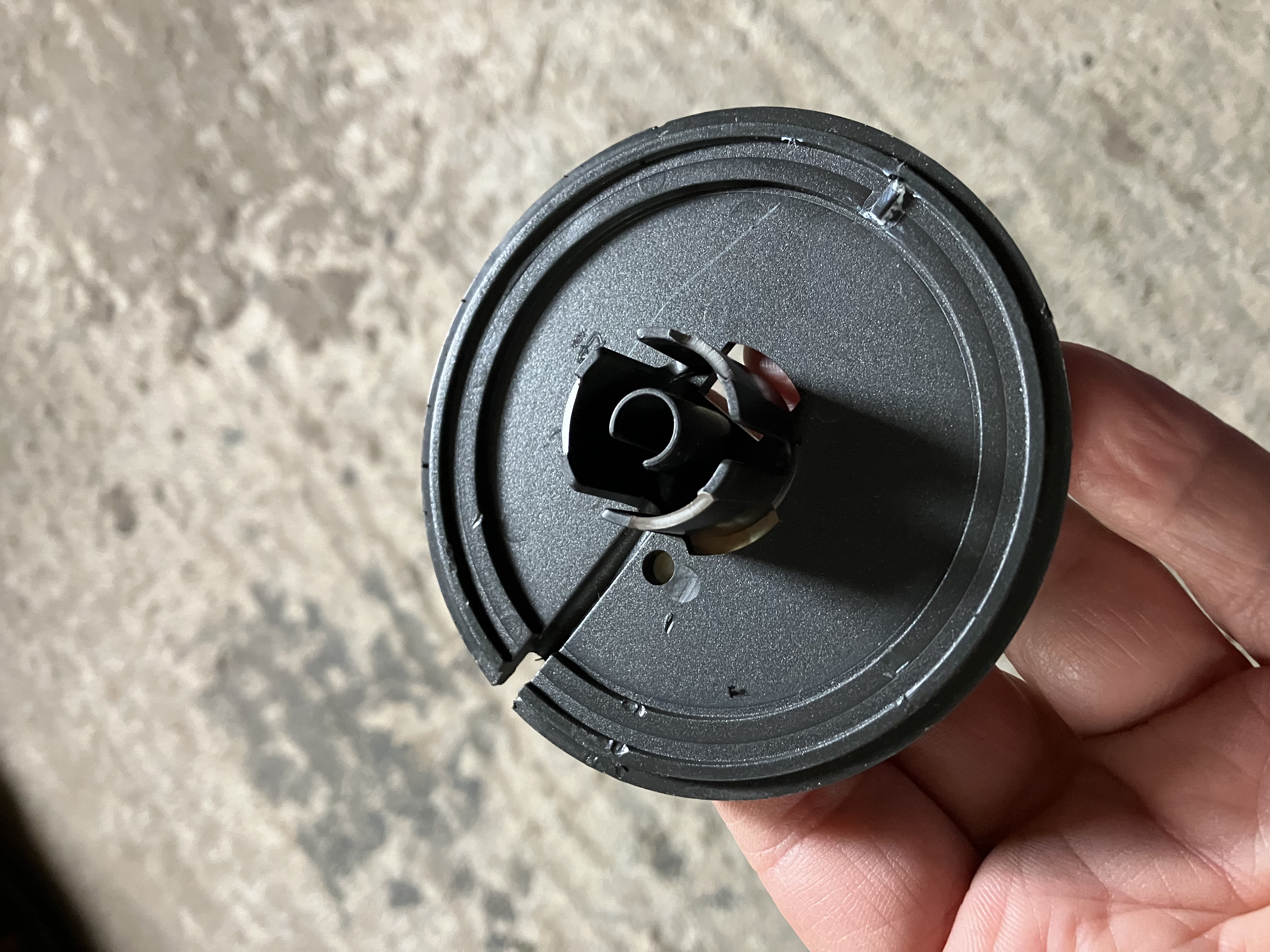
Luckily, when I destroyed mine I took some photos:
 From the bottom, I think if you slide something very thin up between the plastic tab and the metal weight, you may be able to unclip the three plastic base tabs inwards so that they release out of the weight, thus exposing the screws that enable you to proceed further.
Location: Warwickshire, UK
My B&O Icons:


Hi Member 20100, Do you have a link for that part, please?
Can I ask what part you wanted a link to, in case @20100 doesn’t see your post?
There’s an amazon link in one of my posts that still works, in case it’s a replacement laser that you are after.
Location: Warwickshire, UK
My B&O Icons:
29 January 2026 at 15:47 in reply to: Beocenter 9000 Audio, CD, Cassette Player and Beolab Penta speakers guidance #72947Hi Mark and welcome to Beoworld!
The BC9000 speaker 1 sockets will accept 4-pin DIN cables like the ones available from Steve. The extra two pins on the BC9000 speaker 1 sockets are to provide data to the Penta speakers. This enables the display on the Pentas to show Volume and Source. Speakers without displays should work fine without the two extra connections.
Location: Warwickshire, UK
My B&O Icons:
According to the manual there in a ‘tone ringer’ switch under the notepad section (slide to the right) which should be set to position 9.
Location: Warwickshire, UK
My B&O Icons:
The inner wires should still be sheathed – the metal that grips the cable should cut through this sheath as the cable is pushed into place.
EDIT: I have attached the junction box instructions because I am not sure whether we have them in the library.
Attachments:
You must be logged in to view attached files.Location: Warwickshire, UK
My B&O Icons:
Hi David and welcome to Beoworld!
Can I first just check that this is the Beocenter you are referring to: https://beoworld.org/beocenter-8000/
If so, then either BeoLink 1000 (BL1000) or Beo4 should be fine to operate it. I wouldn’t bother with the aftermarket versions, just find a decent working BL1000 or Beo4 on eBay for £30 to £50.
Come back and ask if you have any further questions once you get hold of a suitable remote.
Location: Warwickshire, UK
My B&O Icons:
19 January 2026 at 16:55 in reply to: About to start my 2nd Beomaster 4400 restoration – need tuner restring advice #72711Multicare have now added the BM4401 service manual to Beoworld, and it can be found at the foot of this page: https://beoworld.org/beomaster-4401/
Location: Warwickshire, UK
My B&O Icons:
Second post here, second para states that BC2 goes to A.Opt 0 if no speakers are connected – and post was made by quite an experienced poster/founder member.
https://archivedforum.beoworld.org/forums/t/13784.aspx
And a post here says it goes to A.OPT 6:
https://archivedforum2.beoworld.org/forums/p/12695/110803.aspx#110803
And here:
https://archivedforum2.beoworld.org/forums/p/49635/349244.aspx#349244
Location: Warwickshire, UK
My B&O Icons:
Can you get into the ‘Options’ menu and turn off the Tuners? Both analogue and DVB-HD if there.
Alternatively, try going to the Service menu* and find the option ‘RESET TO FACTORY SETTINGS’. Then try setup again.
* The Service Menu must be activated while the TV SETUP menu is displayed. From
this initial state, the Service Menu is activated in the following way: Beo4: the Service Menu is activated by pressing 0 0 GO within 3 s.Location: Warwickshire, UK
My B&O Icons:
After disabling my mesh network and just going with one router everything now works fine.
Good to hear – I hope it keeps working!
I meant to say, it could also be worth checking that your M3 is at the latest SW level – it should be at 6.5.57689.212515568 which was released on 22 October 2025. Full details of this and earlier versions are listed in the release notes here: https://update.bang-olufsen.com/products/b4ebddbebc6542ad87534e36f49d6a9a
Location: Warwickshire, UK
My B&O Icons:
13 January 2026 at 20:16 in reply to: About to start my 2nd Beomaster 4400 restoration – need tuner restring advice #72527I found a copy of the service manual on the Kose trading site (hopefully attached below), but it should be on Beoworld also – I will check with Multicare.
Attachments:
You must be logged in to view attached files.Location: Warwickshire, UK
My B&O Icons:
Hi Peter and welcome to Beoworld!
Have you tried changing the Line In detection level to ‘disabled’? It’s the setting above the delay setting.
Location: Warwickshire, UK
My B&O Icons:
You have asked this question a few times on the forum so I thought I would have a look for the answer!
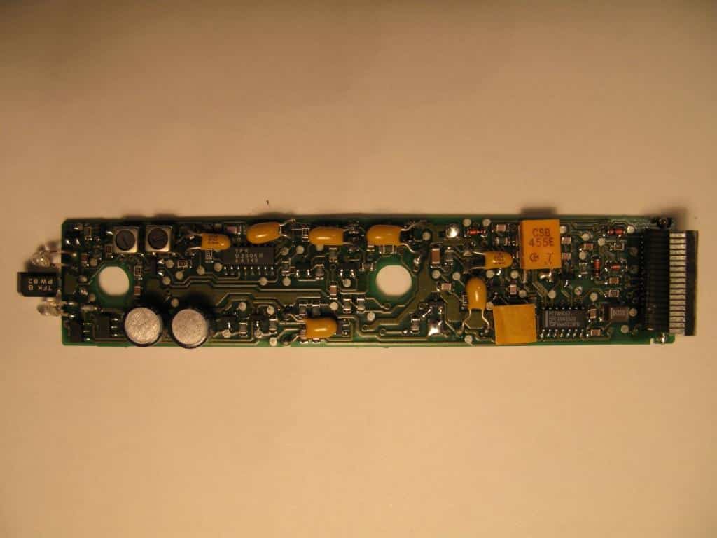
I could see from the circuit diagram in the service manual (available on Beoworld to Silver/Gold members) that it appears to be mounted on a separate board to the main PSU/Pre-Amp PCB (PCB2). I couldn’t find a diagram, so I did a search with Google AI and received this answer:
Transistor Details: The mute transistor designated as TR1 in the Beocenter 2300 is a 2SC4213 SMD transistor.
Part Number: The specific part number for the TR1 mute transistor is 2SC4213.
Type: It is an SMD (surface-mounted device) transistor.
Location: The P-L MUTE circuitry uses two identical 2SC4213 SMD transistors (TR1 and TR2) and two 8.2K ohm resistors, which are mounted on a small, vertical 4-pin sub-board on the main PCB.
Function: A failure in one or both of these transistors is a known cause for audio issues, such as a popping sound when changing sources or one channel being dead, as they control the power-link (P-L) muting function.
Replacement: Replacements for this specific transistor are available from various online electronics suppliers.
If you are experiencing a mute-related problem, it is recommended to test both TR1 and TR2 and their associated components, as either or both can be the source of the fault.I am guessing slightly but I think the small vertical PCB may well be the one that you can see the edge of (between the PL sockets and the 3 capacitors) in the PCB photo at this link: https://kosetrading.com/product/bang-olufsen-bo-beocenter-2300-dab-radio-type-7400-power-supply-part-pcb-2/?srsltid=AfmBOoqX2I4oeoPjxBq0Qiioegkc5mxQQZ2tYzAHYY9v579QJKmKr1MoLocation: Warwickshire, UK
My B&O Icons:
I guess, I’d have to find a descreet place for an IR-Eye…
The Beo4 remotes are so powerful that the IR-eye can probably sit hidden behind another object and still work perfectly. The IR signal will most likely bounce off the walls to reach the sensor.
EDIT: And on the Beo4 with navi button you can adjust the IR power as follows:
Access the service menu by pressing Stby (red dot) + LIST at the same time, and then MENU + (joystick) at the same time. Press ^ several times until the display reads IRPWR: X. Again, 1 is the lowest and 7 is the max IR signal strength (default is 4)
Location: Warwickshire, UK
My B&O Icons:
Hi Nils and welcome to Beoworld!
I posted some details back here that may help: https://forum.beoworld.org/forums/topic/hdmi-connection-for-beovision-7-mk1/#post-33294
And B&O even have some official advice here (but they don’t propose a solution for potential HDCP problems): https://support.bang-olufsen.com/hc/en-us/articles/14630866152081-How-do-I-connect-an-HDMI-device-to-a-Bang-Olufsen-TV-without-HDMI-input
You may not experience HDCP problems if your BV6-23 is HD-R.
Location: Warwickshire, UK
My B&O Icons:
I am not sure whether it helps, but be aware that you can also use a panel from BC8000, 8500, 9000, 9300. However, you need to be aware that the control panel markings are different:
Beocenter 9000 panels (and those for the 9300 and 9500) have a “TIMER” indication on the control panel glass.
Beocenter 8000 panels (and those for the 8500) do not have this “TIMER” marking.
You may be best looking for a complete ‘spares or repair’ Beocenter – then you will have lots of other spares for future problems!
(I used Google AI to get this summary – but am 99% sure that it is correct based upon my previous research!)
Location: Warwickshire, UK
My B&O Icons:
I am not sure why you can’t upload photos normally – I’ll send a message to Multicare.
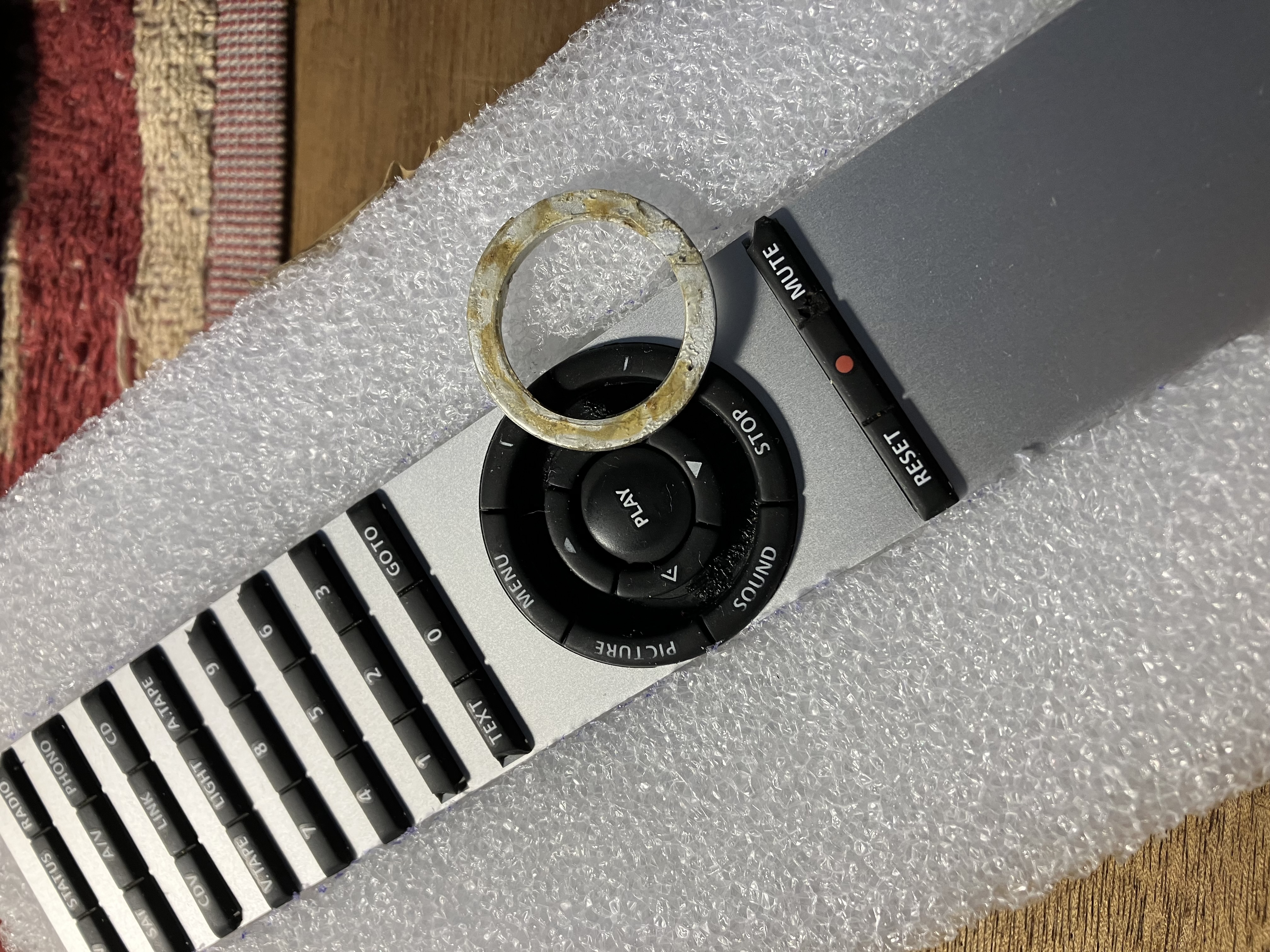
I just dug out an old BL5000 keyboard (actually one that Beoworld member Leslie sent me many years ago) and prised out the metal circle with a guitar plectrum. It came out quite easily, but looks like it was originally glued in place:
Location: Warwickshire, UK
My B&O Icons:
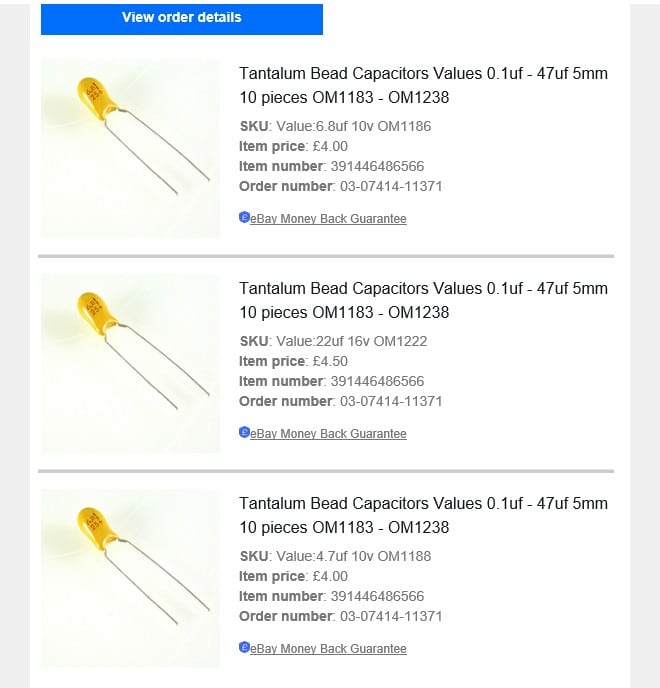
Just to add to the above, like MartinM I went for tantalum bead throughout – see my order below:
Location: Warwickshire, UK
My B&O Icons:
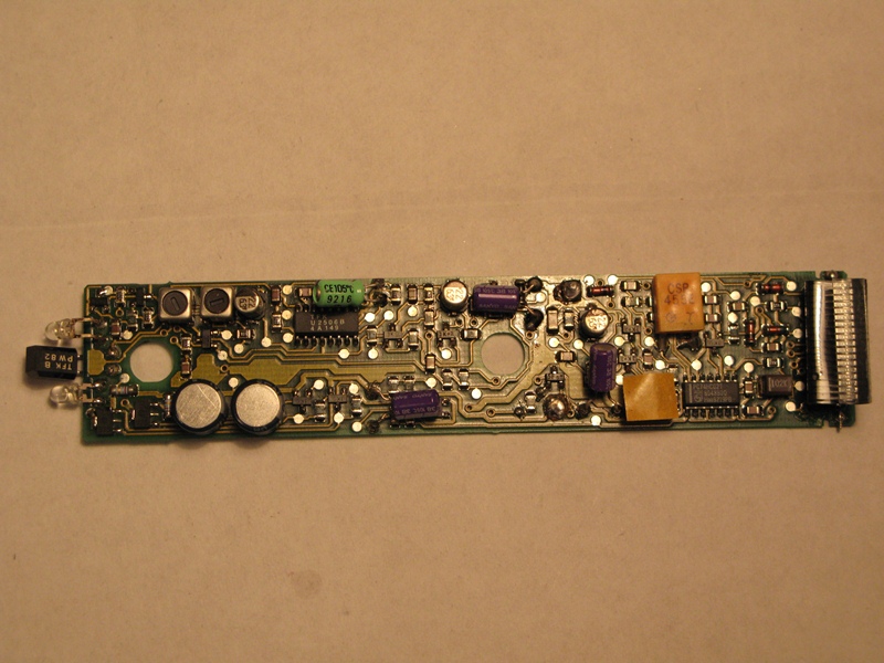
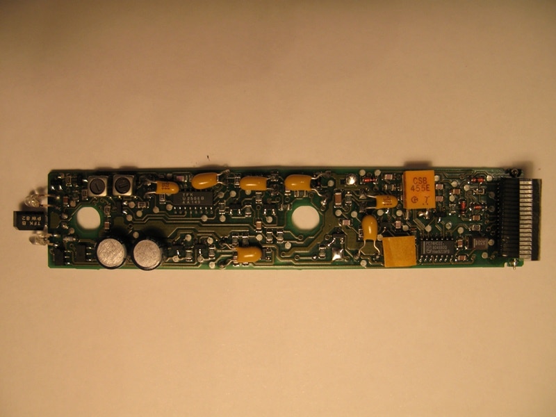
For recap of the IR PCB, there is a guide from Leslie Nelwan at the Beoworld archive showing which caps there needs to be replaced.
https://archivedforum2.beoworld.org/forums/p/9016/89901.aspx
Look a little more than half way down.When I replaced the capacitors in one of my BL5000s several years ago I found Leslie’s post very useful, especially for the capacitor values. I also made use of the photos from a 2010 post by ‘MartinM’ here: https://archivedforum.beoworld.org/forums/t/35123.aspx
The photos are no longer attached, but I kept a copy – see below:
Location: Warwickshire, UK
My B&O Icons:
Have you still got the original Beo4 (not the navi joystick version) and is there any difference in the behaviour of your system when using that?
Location: Warwickshire, UK
My B&O Icons:
-
AuthorPosts