Forum Replies Created
-
AuthorPosts
-
 DillenModerator
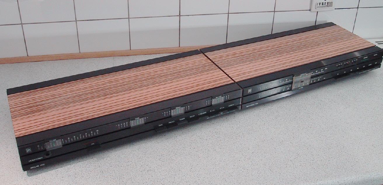
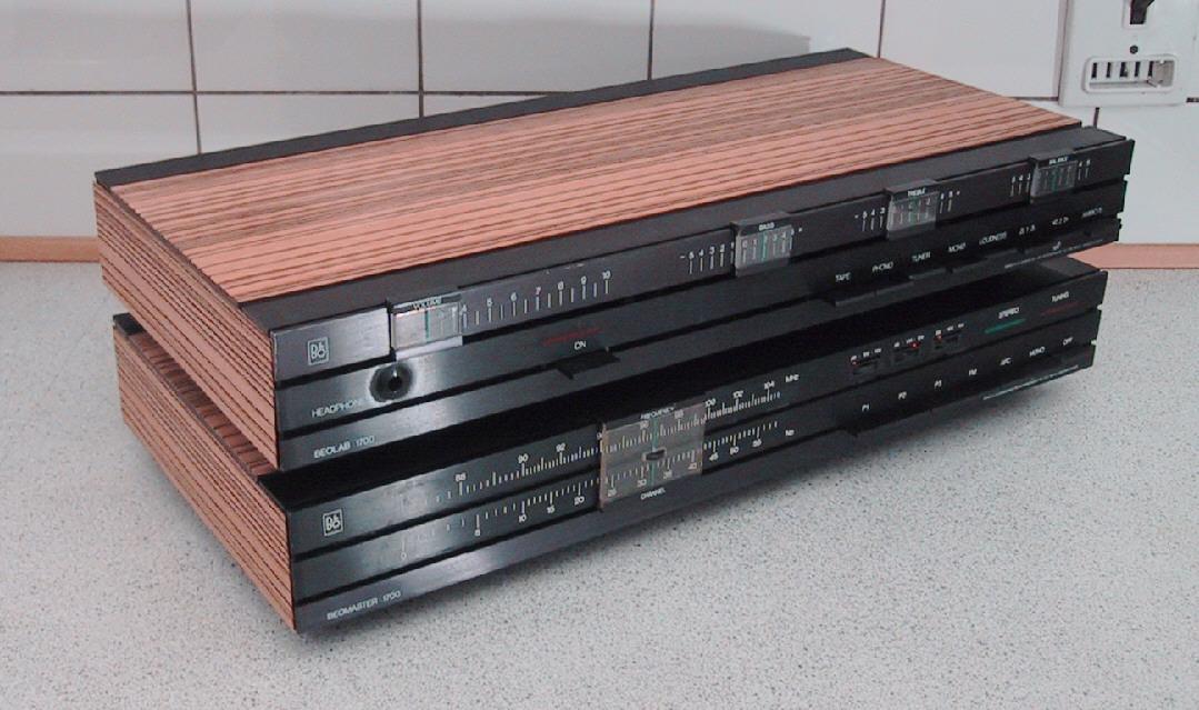
The wooden trim strips are to narrow to really make Zebrano look any good on a BG8000, I think.
I did a Beosystem 1700 in Zebrano many years ago.
To this day I am not sure if I really like it – or even if I actually liked it back then. But the original veneer was too far gone,
so something had to be done, and I was keen on trying.

Martin
DillenModeratorI don’t think I have any of them at present, but it would perhaps be helpful, if you could tell the type of
the single original woofer you have, so they can be matched.VIFA M25WN-40
SEAS 25 F-EWR
SEAS 25 F-EWMartin
DillenModeratorAnd a Beogram 4000C with several defects.
Impressive.Martin
DillenModeratorHave you tried it with a record on the platter?
With no record it will only spin briefly – while the record sensing system operates.The light staying on at all times could be as simple as a shorted transistor.
A bad batch of BC337 was used in production, so it’s not uncommon to see some fail.Martin
DillenModeratorTypical symptom of a slipping belt.
With the Beogram unpowered and platter lifted off, put a finger on top of the
motor pulley, rotate the subplatter (“skeleton” platter) by hand and feel for friction.
There should be a fair amount of friction. If the belt doesn’t “bite” the pulley but instead just
“skates” on it, replace the belt.Yes, Danish Sound Parts is both Danish, Parts and Sound.
Martin
DillenModeratorThe crossover can not introduce a signal. It’s all passive.
All sounds come from the amp.But it could be, that the diaphragm wasn’t properly centered, so it now rubs on the magnet or center pole piece.
Martin
DillenModeratorWhen the problem was with the string drive, it’s much more likely that the offset is
between the carriage and the string rather than between parts of the mechanics.
Adjust the black excentric at the foot of the carriage.Martin
DillenModeratorNot sure if this is what you are doing, but NEVER run these decks without the subplatter and platter!
Martin
DillenModeratorBeomaster 4400 rosewood.
Mint condition.
Completely restored.
Not cheap.
PM me if you are seriously interested.Martin
DillenModeratorPerhaps the spindle hole in the large pulley is worn out of shape from using a wrong belt (too tight)?
Martin
DillenModeratorA wrong belt can indeed mess things up. And it can even damage the delicate sinter bronze motor bearings.
It’s impossible to say if what they sell will work. I have seen countless wrong belts sold everywhere.
Correct belts are available from Danish Sound Parts – also the wedge-shaped one for the carriage motor.Martin
DillenModeratorAvailable in polycarbonate, injection molded :
https://www.dksoundparts.com/product/beocenter-5000-7000-7002-spring-holder-for-turntable-dust-cover/Martin
DillenModeratorStay with the original and have them refoamed.
They are unique for these models.
6,4 Ohms if I remember correctly.Size is not everything when it comes to speaker drivers. Look at the list of T/S parameters.
Martin
DillenModeratorThere should be no nylon washer – but in some Beocords you will find a bronze spring plate.
Does the large pulley wiggle on the metal spindle?
Has the thread on the spindle been damaged?Martin
DillenModeratorWas this Beogram moved to a different mains voltage area?
Replace the transformer and make sure it is set up correctly for the actual local mains voltage before connecting mains.
Having siad that – if the Beogram suffered an over-voltage situation, some of the electronics may also have been damaged.Martin
DillenModeratorBad opto sender IR LED at the threaded shaft.
https://www.dksoundparts.com/product/ir-led-for-beogram-6006-8000-8002-beomaster-8000/Martin
DillenModeratorRosewood it is.
Teak is lighter and has a finer grain pattern.
These speakers won’t ever degrade from foam rot, because no foam was used.
They are excellent speakers.Martin
DillenModeratorIt was not meant to be disconnected.
I always desolder the connector from the board.Martin
DillenModeratorNormally, these remote controls need very little attention.
Martin
DillenModeratorCheck for excess ripple on the supply voltages (bad filter capacitors).
If your CPU module has an electrolytic capacitor near the edge connectors, replace it.Martin
-
AuthorPosts