Forum Replies Created
-
AuthorPosts
-
 MadskpGOLD Member
Nice and now we know what’s the difference between the BW1 and a normal PL output. I see following in your BW1 capture (second screenshot equals the previous message): 0011 0001 1110 0111 1111 0000 0000 1001 0011 0011 0100 1100 1011 0000 0000 0101 0000 0000 0001 which equals those hex values: 31 E7 F0 09 33 4C B0 05 00 1 The Active kit sends the following: 0011 1011 1100 0000 0100 1000 0110 0100 0001 1000 1 0011 1011 1101 0001 0100 0000 0000 0000 0000 0000 1 which equals those hex values: 77 80 90 C8 31 77 A2 80 00 01 At least that “33 4C” data block I think I have seen before on AAL/MCL communication.
Would it be helpfull if I export the data to some binary files and upload them in a post?
Location: Denmark
MadskpGOLD MemberNow I have a logic analyse and have tried connecting it up to the datalink pin 6 in the powerlink connection between the BW1 and the BL3500 MK2:
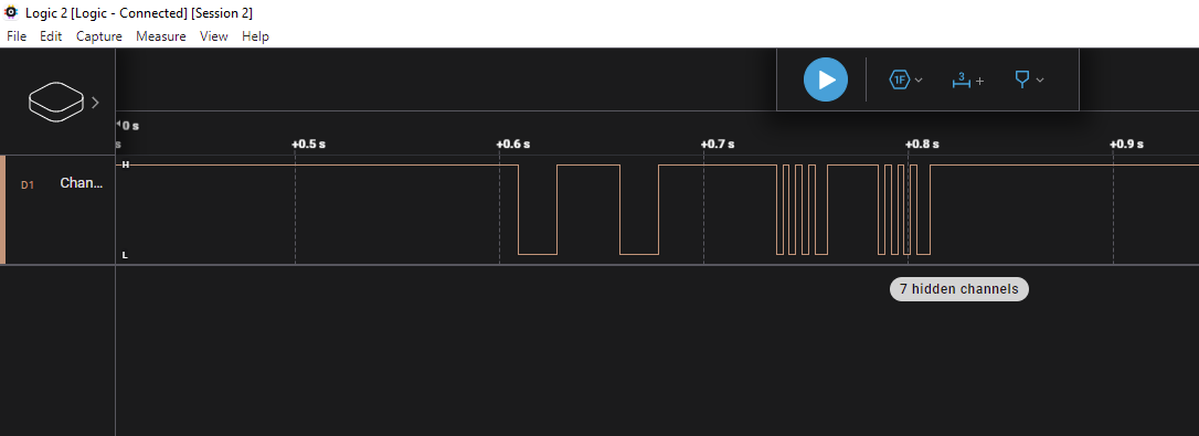
When activating the BL3500 MK2 via the BW1 with an ATAPE command I get this

Followed by this

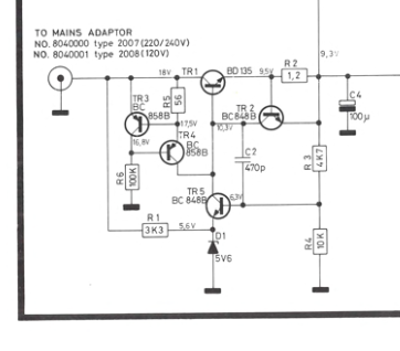
Not that I am able to make sense of this command. But I have insted tried to compare it with the datasignal on pin 6 in a powerlink cable from a Beolink Active conencted to the BL3500 MK2
 I can see that there are some differences in the structure of the first two parts of the signal, but also the part from the second picture from the BW1 data signal is not at all in the signal from the Beolink active, so clearly a different datasignal from the BW1 compared to a Beolink active
When presing standby with the BW1 connected to the BL3500MK2 I do not register any data at all. Probably the Bl3500 turn off because the powerlink on signal on pin 4 disappereas.
Location: Denmark
MadskpGOLD MemberHello guys and thanks for all the inputs.
Glad to hear that I am on the right track.
Now I will try with some different commands and see if I fully understand it.
Location: Denmark
MadskpGOLD MemberMadskp wrote: Found one on Ebay and ordered it. Should be nice to have for things like this Nice! I think most of these cheap ones still work with the Saleae application. It’s a straight forward to use tool.
I have got one now and it is working with the Saleae application with the excaption of the channel naming on device being 1-8 and ind the applicattion being 0-7, but I think I can mange that.
I wan’t to be comfortable using it before I am visiting my parents again next weekend and doing measurements on their BS1.
Therefor I have done some testing with different data sources, and can see that I might need some verification of what I am doing.
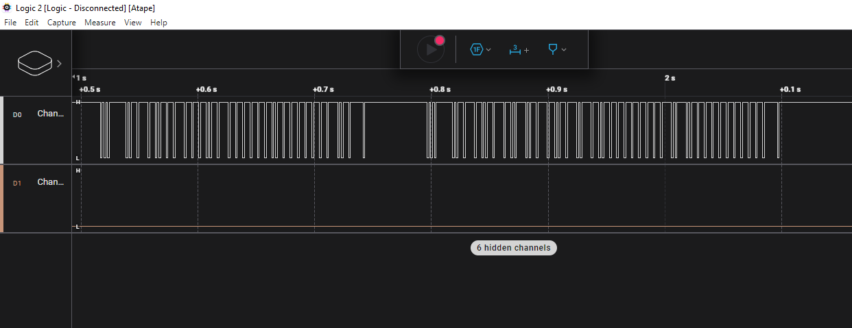
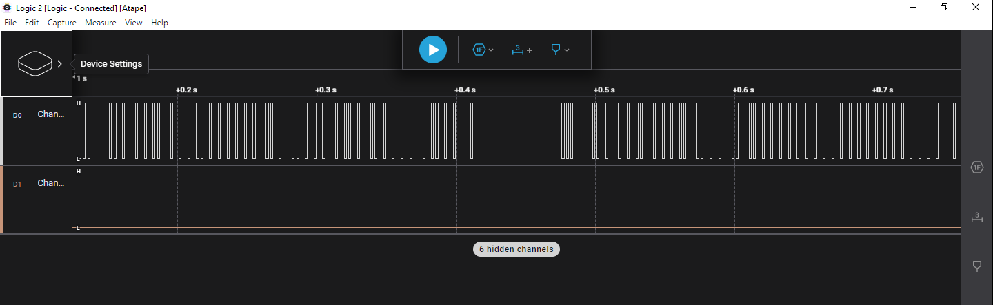
I have taken this screenshot from a recording of an A.TAPE command on the tape port on a MCL2AV:

What I need to know is does this look correct, or do I need to do some settings in the Saleae application?
Also if I export the data in binary format what is the best way to compare them to those datalink commands that are available in different online projects?
I have found a HEX editor, but unsure what format I must show the data in to be compareable (BInary, HEX, Decimal ??)
Thanks in advance
Location: Denmark
MadskpGOLD MemberIs there a red LED with lights on?
If it is the later version of the BL3500 (MK2) it will not react to source commands if it is not connected to an audiomaster.
To check for signs of life you could try to press Menu, 0, 0, GO on your remote (is it a BEO4 remote you have?)
This should give som basic information in the display like sw version
Location: Denmark
17 January 2024 at 11:11 in reply to: Setup BeoLab 2000 to get audio from Beolink 1611 converter #51163MadskpGOLD MemberGood to hear that the problem was solveable and your setup is working again ?
Location: Denmark
MadskpGOLD MemberSad to hear that it ha come to this point although I fully understand the reasoning behind it from your perspective Lee. Good luck on finding a buyer.
I just hope that the forums can continue to exist in some form in the future.
Regarding the Archived forums, the product pages, the FAQ’s and the Beotech sections, and also the current forums those can actually be acessed through the Wayback machine on archive.org.
However none of the search, and/or filtering functions seems to work in these archived versions of the pages, so a very manual process to find information that way.
Location: Denmark
MadskpGOLD MemberOne thing to notice. If my memory serves me well maybe the 0 button has to be pressed in and stay in for the TV to be off.
Location: Denmark
MadskpGOLD MemberA multimeter reading does indeed show negative polarity (the DC output voltage on the old unit is now indicating 19-volts, hence the need for the new 12v DC power supply).
You might not need a new power supply. If the power supply is unregulated, it will read “high” if there is not a load applied. You might want to take the multimeter reading again with the either the device connected to the power supply or a dummy load that simulates the device load. Glitch
I remember from another thread that the forum user GUY had the same experience with the power supply for a MCL2AV, where he meassured it at 20V even though it was rated for 15V
Location: Denmark
MadskpGOLD MemberCan you tell/see, if the laser lens moves in and out to search for focus, when you press CD with no disc loaded?
When I press CD without a CD loaded nothing happens with the laser, and the display shows CD
If I press CD once more the laser will move ind and out and the display will show CD <>
Location: Denmark
MadskpGOLD MemberSome time have passed and based on some older forum post’s I tried a recap of the Philips CDM board on the drive mechanism.
After that I played a full CD. However after playing that first CD it would not play anymore, but after trying some of the test modes from the service manual I have now been able to play several CD’s without problems.
However there is one issue that I notice. When I press CD it will close the clamper and show CD in the display, but not start playing before I press CD once more.
This also applies if I start from standby by pressing CD. Then the display will show CD 1 but not start to rotate before I press CD once again.
A minor issue, but not the way it was supposed to work. Any suggestions as to what this could be?
Location: Denmark
MadskpGOLD MemberAn archived post indicates that the center pin on the 12v DC input for the MCL 2 Expander is NEGATIVE. Can anyone else confirm this with absolute certainty?
The diagram in the service manual also show this

I can confirm that my MCL2AV also has the center pin negative (even though the service manual diagram for that shows the opposite).
If you wan’t to be sure and have acces to a multimeter you should make a continuity test between the center pin and a ground point like the shield screw terminal
Location: Denmark
MadskpGOLD MemberFrom memory back when we had something like that at home you just press one of the number buttons to turn on the channel that number is tuned to.
You turn it off by pressing 0
Hope this helps
Location: Denmark
MadskpGOLD MemberDid you use a B&O original 8-pin cable, and connected that to your DIN to Mini-Jack cable?
No the cable itself is from af B&O 7 pin DIN cable, but i have soldered new conenctors in both ends of it.
I think the big difference with the B&O original cable is that the B&O cable has a shield, besides the GND for the Left and the Right channel.
Yes, but I have used the shield in this cable as ground.
And that this shielding is connected to pin 3, 5 & 7 on the male connector. Do you agree?
Yes I have connected that shield to pin 3, 5 and 7 on the 8 Pin male DIN connector in the BL3500 end.
Do you think that I could use a DIN to Mini-Jack cable that could do the same, if it has separate leads for Left, Right, Ground Left, Ground Right and shielding?
It could be worth a try. The shielding should then probably only be connected to the outer ring of the DIN connector and not be connected to the ground pins (3, 5 and 7).
BTW on my adapter cable there is no connection between the ground pins and the outer ring in the DIN connector
Location: Denmark
MadskpGOLD MemberI have just tried to make a test with my BL3500 MK1.
I could not find my adapter cable I have made for it at first so I started by making a minijack to 7 pin DIN cable where I connected pin 3 and 5 in the DIN plug to ground on the minijack, and and pin 1 and 4 in the DIN plug to L and R in the minijack.
Connected to my Macbook pro connected to power I was getting a noticeable hum when nothing was playing. When I removed the power cord from the Macbook the hum disappered.
Later I found the adapter which is a 8 Pin male DIN plug in the speaker end. Pin 3, 5 and 7 is soldered together and is connected to the screen in the cable (original B&O AUX cable used for this) and connected to PIN 2 in a 7 Pin female DIN connector in the other end of the adapter.
Pin 1 and 4 from the 8 Pin male DIN is connected to pin 3 and 5 in the 7 Pin female DIN connector in the other end of the adapter.
Also I have pin 6 (data) connected between the two DIN plugs.
When I use this adapter with a normal minijack to 5 Pin DIN cable I get no hum (that I can hear). Why this makes a difference I can’t tell.
So this hum issue could both be because of power sources and signal cables or a combination of these.
Location: Denmark
MadskpGOLD MemberI forgot, something that still bugging me: Whatever the preferences I check or not no way to display song name on the Beolab 3500 screen. Any idea? Thanks.
It seems that this might never have worked for the Beolab 3500 display, but only on BS3000, BC2, and maybe other music systems according to this post https://forum.beoworld.org/forums/topic/masterlink-usb-adapter/page/2/#post-28470
Location: Denmark
MadskpGOLD Member
@Madskp: from my Linkplayer experience: • BS3000 displayed, on activation, that the source was either N.RADIO or N.MUSIC. It then displayed the song and the author via horizontally scrolling displayed; or, the radio station and the song. • BL3500 only displayed N.MUSIC or N.RADIO; no additional data was displayed.Thanks for clarifying this. Also explains why user Matador never got the BL3500 showing Metadata in a BL3500 when he was playing with the Beoport and LInkplayer software earlier this year.
Location: Denmark
10 January 2024 at 11:05 in reply to: Controlling a Beomaster 6500 via the TV/Aux Datalink’86 pin #51976MadskpGOLD MemberAnd success! I found the “secret” commands to unmute/mute the Powerlink speaker: unmute – 0x1C mute – 0x1D Prerequisite is an already running Beomaster.
Just to understand this correctly. You can then activate the Beomaster in a muted state via the datalink’86, and then afterwards unmute it also with datalink’86. Is that correct?
Location: Denmark
MadskpGOLD MemberVisually it looks like a Beovox C30/C40 or CX50, but I haven’t heard of this variant before, Guess there can’t be many differences, but maybe someone else can chime in. I can see that the various repair shops has parts for it, so can’t be that rare parts vise
Location: Denmark
MadskpGOLD MemberAbout BeoLab 3500 MK1 In the meantime I learned that BeoLab 3500 til serial number 19343452, are MK1. All serial numbers from 19343452 and up are MK2. So mine (ser. 1787 xxxx) is a MK1 (like you mentioned before Madskp). Also I read on the archived forum (post by Keith Saunders) that the Service Manuals for the BeoLab 3500 MK1 and LCS9000 are the same. In the service manual of the LCS9000 the Pin layout of the DIN connector is shown like this: This is the way I created a Mini-Jack to DIN cable before for a LCS9000. And it worked. Using the same cable for the 3500 MK1 gives a hum.
Btw I am no really sure where you are going with this as your wirering seems to be as it should according to the specifications in the servicemanual for the LC9000/BL3500 MK1
I will see if I can replicate the hum on my BL3500 MK1 and repport back with my findings.
Location: Denmark
-
AuthorPosts

 I can see that there are some differences in the structure of the first two parts of the signal, but also the part from the second picture from the BW1 data signal is not at all in the signal from the Beolink active, so clearly a different datasignal from the BW1 compared to a Beolink active