Forum Replies Created
-
AuthorPosts
-
 MadskpGOLD Member
When I press Menu it activates the timer with display “On 0:00”.
Ok that would indicate that you need to press Menu once more to get the timer away. Else the numbers are going into the timer settings.
I have tried this many times probably because I was pressing Menu Menu to fast in a row, so try to adjust the timing between the key presses
the document with the MLGW compatibility is attached. You can find it on the site https://mlgw.bang-olufsen.dk/source/documents/
Thanks a lot. Very usefull. I have nvewer looked at info for the ML gateway, so thats why I did not have that info
Location: Denmark
MadskpGOLD MemberIt is in a working setup with BS5 as audiomaster and a beolink converter NL/ML as videomaster to get access to my Beovision Avant 55 MKI. All commands seem to work properly.
Then it sound odd that the Menu 0 0 Go command does not work.
How about Menu 0 2 Go (shows status of Masterlink)?
I removed it from the wall and the type plate shows sw: 2.0 Type No:1601.
When it was delivered with SW 2.0 it is most probable a MK1 version. To verify that further you can see if MCL is engraved in the metal beneath the 8 Pin DIN connector on the back. You can also check the serial number MK1 has serial numbers lower than 19343452
If you did not buy the BL3500 from new there is of course a slight chance that a former owner updated the software, but the only wa to confirm is the Menu 0 0 Go command
And BTW since it’s most likely a MK1 the key sequence is only with one press on Menu.
I would like to reroute the light commands from my BL3500 to my Beolink Gateway which is only working from sw version 3.3.
Can you tell where you have the info regarding the Light commands and software version from? Reason for asking is that in another thread https://forum.beoworld.org/forums/topic/bl3500-and-the-mcl-pl-connector/page/3/#post-22047 I am trying to keep a list of software changes in the BL3500 and would like to get as much info as possible, and with sources if possible.
Thanks in advance
Location: Denmark
MadskpGOLD MemberI tried to find out the sw version of my BL3500 (from 1994) but neither combination (“Menu Menu 00 go” or “Menu 00 go” worked. Any idea what can cause this? Kind regards, Luc
Is the BL3500 in a working setup and/or does it react to other remote commands?
Location: Denmark
MadskpGOLD MemberI still have to take the video engine board out to see if there is corrosion, from the top it looks fine. I found the capacitor on ebay, https://www.ebay.ie/itm/292412377560 just €8. I will update you guys if that fixes it. Thanks for all the help!
Nice. Looking forward to your findings. Would be great if replacing this could make these great TV’sluve a little longer
Location: Denmark
MadskpGOLD MemberBtw do you see any corrosion on other components arround this capacitor on the board?
Hopefully it did not damage other things than itselfLocation: Denmark
MadskpGOLD MemberBased on the markings on the plastic 0.22uf 5.5V ina Google search it is not a battery but a super- / backup capacitor.
It seems to be widely available and at a fair price
Very interesting if replacing it actually solves the problem. The on you have seems fairly corroded indeed
Location: Denmark
MadskpGOLD MemberAnother possibility for testing the TV is if you have an Apple TV with one of the confirmed working remotes mentioned in this thread https://forum.beoworld.org/forums/topic/apple-tv-siri-remotes-and-ir-beovision
you could be lucky that would start the TV although limited to turning on and volume control
Location: Denmark
MadskpGOLD MemberHi all, Please let me know if there are any issues since the site transfer
Hello Mark.
It lools like the member status has not been transfered correctly on the forums. In the posts I have been looking at I only see bronze members where I know more than one of them were Gold members including myself.
On the main web site my member status seems to be correct.Location: Denmark
MadskpGOLD MemberUnfortunatly it doesn’t solve the pin situation. Right after clicking STOP I am at the snowscreen again.
I Hve tried to acces the Pin code menu on my Beocenter 6 Bey pressing Menu + << + << + stop, and that seems to work fine, so the command is right.
To reproduce the Behaviour you have I tried to set a new Pin code and let the TV be with out power for 30 minuttes. After that I used the service Pin code 11111.
When I did that I get the same behaviour that you are experiencing.
I have not been able to find anything that documents why this is so, but my best guess is that the only reason for acesing the Pin code menu is to change a pin code or to delete it.
This can only be done by having the correct pin code or the Master pin code, so no need for this to function when the service pin code is used.
So You will have to get the right pin code or the Master pin code from a dealer to get it working. The service pin code can only be used for 12 hours according to the service manual.
EDIT: I solved this by going into the TV with the Master Code 11111 and then with 0 0 and go to enter the system menu and reset to factory settings. Strangely I got back the option for TUNING.
Great that you got that part working.
Location: Denmark
MadskpGOLD MemberWow, who knew this soldering thing would be so difficult! Ive melted the plug! think I need a finer, smaller soldering iron and finer solder…
Sound like it. Those plugs can be quite fidely to work on
Location: Denmark
MadskpGOLD MemberJudging by the Peter Pan thread it was a way to keep legislation. I guess a cheaper way than to reconstruct the products
Location: Denmark
MadskpGOLD MemberTry pressing menu twice in the sequence.
If I remember correctly you have to be in the menu before doing what the manual saysRegarding scarts you have to assign a source (V.tape/DVD etc.) in the connection menu
Location: Denmark
MadskpGOLD MemberIf I get it working I was going to buy a beomaster 2000 to go with it
Then the datalink connection on pin 6 will be relevant
Location: Denmark
MadskpGOLD MemberLast question, honest… do all of these wires have to be soldered into the plug?
If you not gonna use it with a datalink compatible Beomaster the yellow wire is not needed.
The rest is mandatory
Location: Denmark
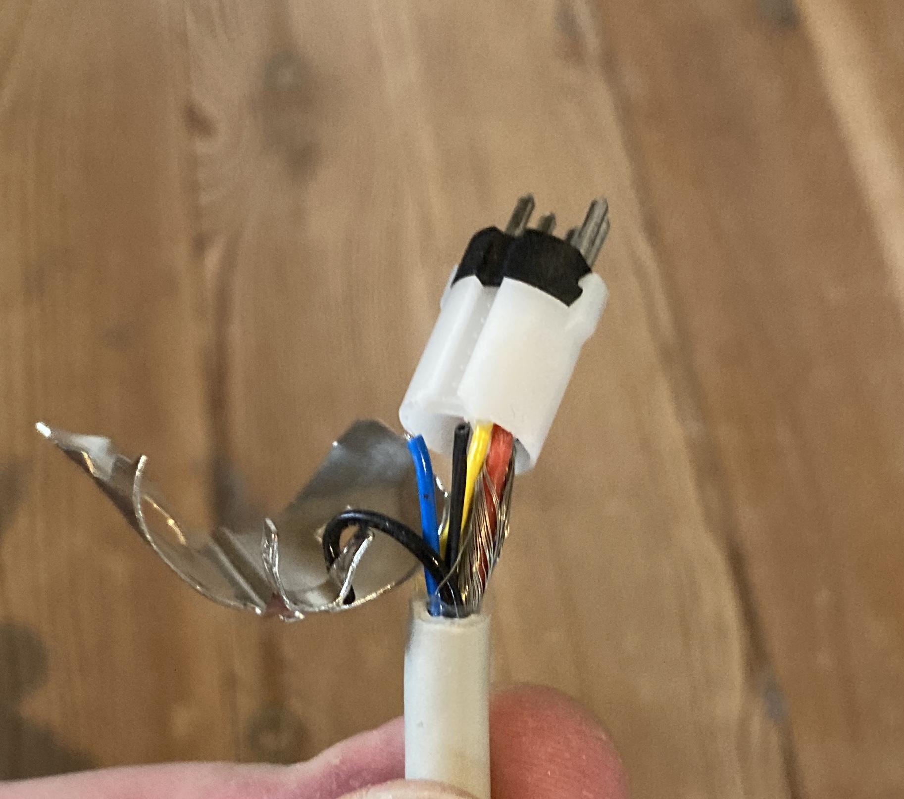
MadskpGOLD MemberThank you again. just for an idiot guide and to be totally clear, you mean shield are the bare wires that surround the coloured wires inside the cable when I cut it back? there is no other bare wire or wires so I guess that’s what you mean?
That is correct
Location: Denmark
MadskpGOLD MemberShield is the bare metal wire
Take a look at this post fo the pinout. On some connector the numbers are engrave in the plastic
https://forum.beoworld.org/forums/topic/wiring-diagram/#post-25003
Location: Denmark
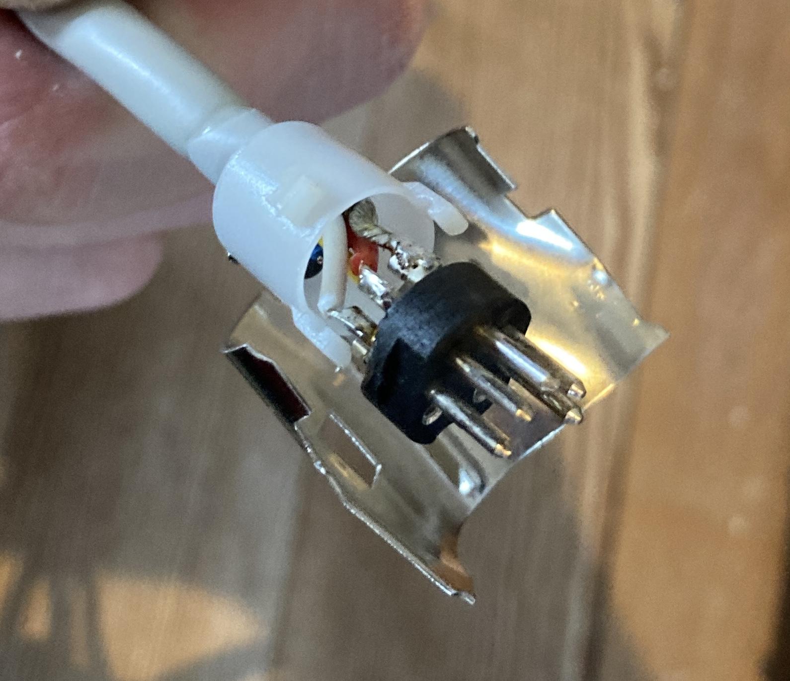
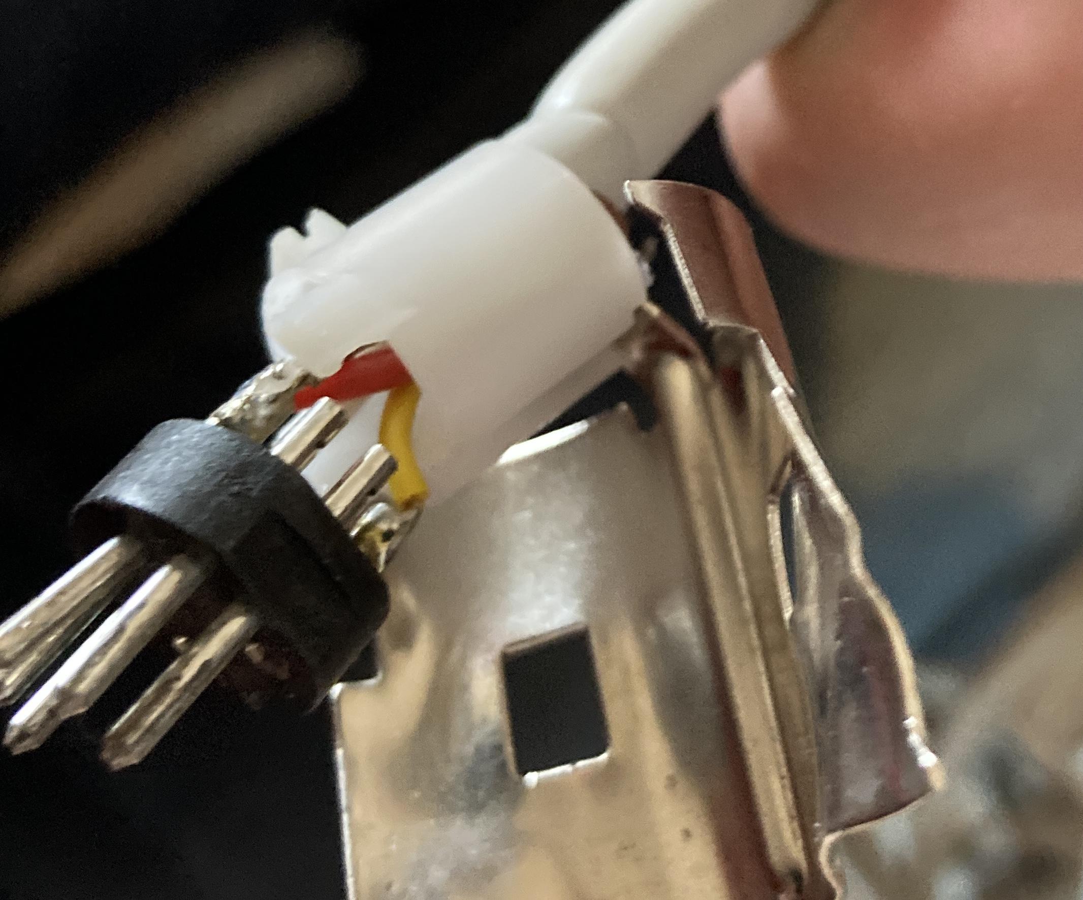
MadskpGOLD MemberI have opened up the DIN connector on a broken Beogram 2000 I have and these are my findings:
Blue and thin black wire is not connected. Thick black wire is connected to the metal part of the plug

Shield is connected to pin 2 in the DIN connector, red to pin 5 and white to pin 3 (note that pin 6 and 7 is unscrewed in this connector)

Yellow is as you have noted yourself datalink and is connected to pin 6

Hope this helps in getting the Beogram functional again
Location: Denmark
MadskpGOLD MemberIt’s thread drift for this thread, but I am helping a relative sort out some tech/AV gear and have a Google Chromecast HD for a few days. I just tested it with my BV10-32 and realised that you can setup the Google Chromecast remote to control the TV’s volume in the same way that a siri remote does! The Chromecast menu also offers the facility to turn the TV off/on (I could only get ‘off’ to work) and to change inputs, but I couldn’t get the latter to work. I am quite impressed that such a cheap device (£35 in UK) has the IR codes to control a Beovision!
It is indeed quite interesting how both Apple and Google are integrating these B&O IR codes. Maybe they are just using common libraries of IR codes that are available. However in case of B&O they also need the transmitter to be able to transmit 455Khz IR codes that other brands are not using, so I guess the hardware must also be made for it.
Sound like the Google Chromecast is not perfectly working though which was also the case with the 1st. Gen siri remote.
Location: Denmark
MadskpGOLD MemberJust read your post again, and can see that I did not get the turntable in the cabinet in my first reading.
It could be a Beocenter 7700 wich also fits the description of the remote
https://www.beoworld.org/prod_details.asp?pid=407Location: Denmark
MadskpGOLD MemberBang and Olufsen really have had many systems with smoked glas and red LED lightning. Just a few examples here that might hint something more:
Beosystem 6000
https://www.beoworld.org/prod_details.asp?pid=1253
Beocenter 9000
https://beocentral.com/beocenter9000
Beosystem 4500
https://www.beoworld.org/prod_details.asp?pid=419
Location: Denmark
-
AuthorPosts