Forum Replies Created
-
AuthorPosts
-
 MadskpGOLD Member
Looking at the diagram for the MCL2A the data line has no connection to anything in the relay box which might suggest that the option settings are stored in the IR eye.

I might try with another IR eye to see if it act any different. I belive the one I am using here is one I have not used before, so it could have issues
Location: Denmark
MadskpGOLD MemberI have tried Link option 1-6 and do not see any change in behaviour no matter which one I choose, so I am not sure if the options settings does anything for this particular setup.
For the BL1615 it may also be worth trying V.OPT settings, as that is what you would do if there was a connected TV.
I have now tried L.OPT 0, A.OPT 0 and V.OPT 0, and in all cases it still reacts to the remote commands, so guess the option settings does not work in this setup
Location: Denmark
MadskpGOLD MemberFor some reason the linkroom setup responds to both normal audio commands and LINK audio commands today. Very weird. I can’t tell why it differs today, but might have to do some more long term testing.
Does the IR eye/BL1615 combination accept Option programming? This could explain the change of response. Also, I am not sure whether the Option setting is stored in the IR eye or the BL1615 – you’d have to swap between components to test.
Thanks for the input. I have tried Link option 1-6 and do not see any change in behaviour no matter which one I choose, so I am not sure if the options settings does anything for this particular setup.
I have yet to try option 0 though. That would at least give a hint to wheeter or not the options settings has any effect at all. That will be for my next testing run.
Location: Denmark
MadskpGOLD MemberI did a little more testing today.
For some reason the linkroom setup responds to both normal audio commands and LINK audio commands today. Very weird. I can’t tell why it differs today, but might have to do some more long term testing.
This does make scenario 2 and 3 in the first post less interesting as there is now risk of conflicting commands.
I have also added my BC6 to the ML part of the system, and the TV can be activated from the 1615 link room with normal video source commands
I have also tried to replace the 1615 with both a 1611 and 1614 Beolink converter and it seems to work the same as the 1615 except they do not react to video commands.
To be continued…
Location: Denmark
MadskpGOLD MemberPerhaps if the audio was fed into a Playmaker, auto-sense on its line-in could switch on connected PL speakers and you would have Beo4 volume control also? You’d probably need the PM in A.OPT 4 so that it will respond to the ‘link mode’ volume commands that are used to activate the BL1615,
Oh yes, didn’t think of that as an option. That would be an even more seamlessly solution, especially if the BEO4 is programmed to send link commands.
and you’d have to avoid the A.MEM command as this would put the PM into Airplay mode.
Yes A.MEM can not be used from the main room in this scenario as the PM also seems to prioritize Airplay over Line in.
Location: Denmark
MadskpGOLD MemberAnd to be complete, even the fully wired PowerLink cable might not be enough to get it working ? https://forum.beoworld.org/forums/topic/beoplay-connection-hub-beolink-passive/
Yes that’s right. This might also be an issue with the BLC
My latest plan is to use a BLC (I do have a ‘JOIN’ IR eye already) and two BL7-4s (that I now have as well). I will see to feed the L/R speakers with Left and Right signals only. I took the BL2000 to the garage for a ‘fit’ and I fear it will be a bit small in the 3x6m space. And now I have a purpose for those 7-4s!
Talking about an upgrade 🙂 But this will avoid those extra boxes for sure (unless you count the 7-4s as boxes).
The BL2000 will move to the garden I reckon (cabled).
Or you could get an extra BLC now that you have the powerbox 😉
Location: Denmark
MadskpGOLD MemberOne thing that just came to me if you have the Beolink passive in mind. If it makes sense could you use the BLC with an IR eye as the linkroom and the the passive connected via powerlink to drive passive speakers?
The powerlink cable has to be fully wire for this to work
Location: Denmark
MadskpGOLD MemberAlso a picture of my messy test setup
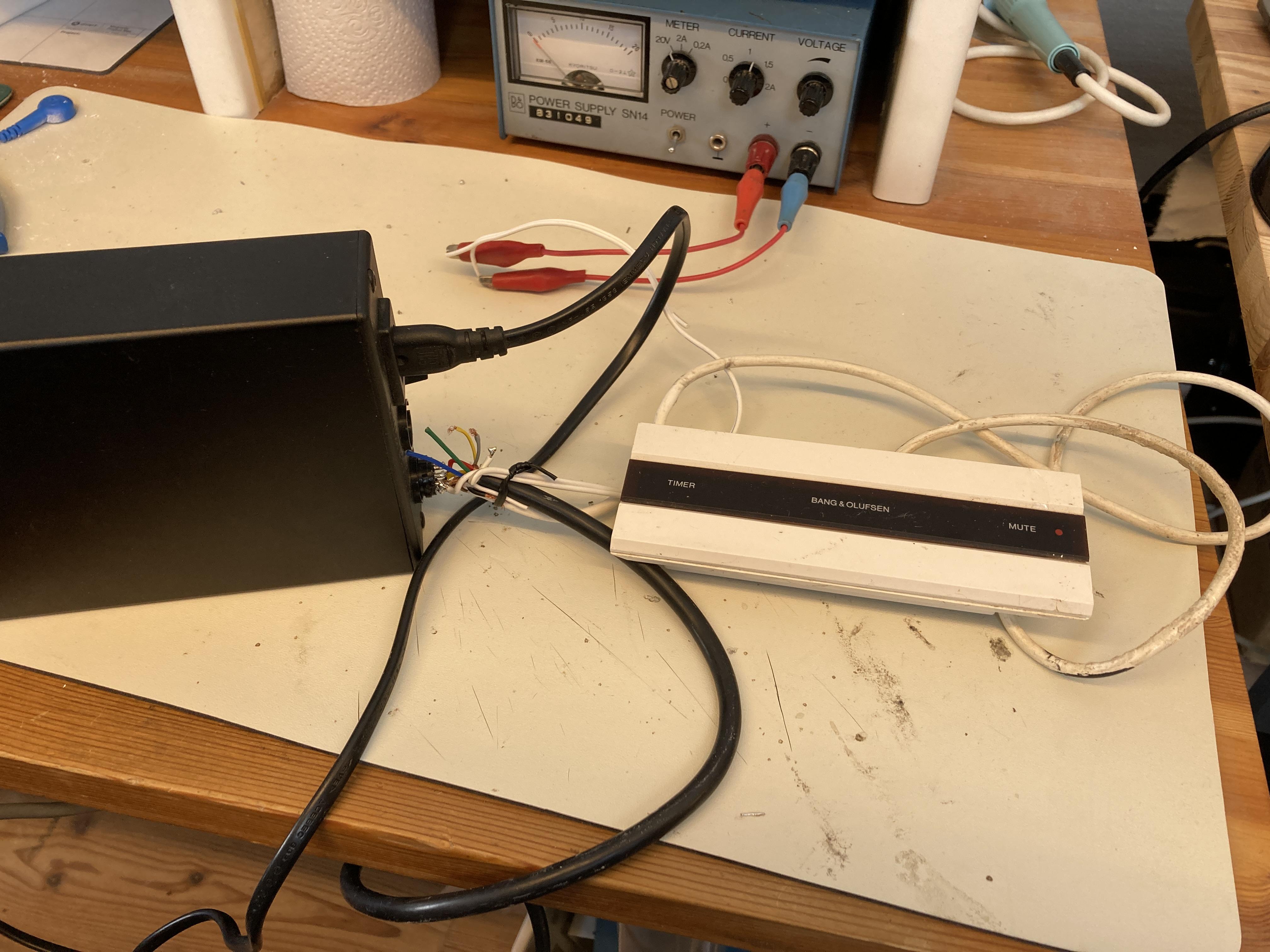
I will also do some followup with video master sources and check if other Beolink converters like the 1611 and 1614 will do the same
Location: Denmark
MadskpGOLD MemberI can try to test it if I can find the time later this weekend
I have tried now, and the Beolink passive provides 0V on both power and data lines when not connected to other ML equipment
Location: Denmark
MadskpGOLD MemberOk so if I understand correctly the ML power box only deliver the 0.25/-0.25V for the datalines and not the higher voltages on the pink and blue wires?
Yes, it provides the termination voltages for the datalines and 5V to the ML Power + pin. Probably ML Power – is also supplied with -5V but I don’t think any of the common ML devices uses that. As I said earlier everything will communicate just fine if you provide it with the data termination voltage and 5V on the pink + blue/white cable.
What could be the reason for not having the supply of the data voltages in the BLC NL/ML?
I have never looked into a BLC and there is no public schematic available. I don’t know if it is using the old ML ASIC or a discrete solution. In any case I put my bets on a hardware design issue. They either may have just forget about that feature during development or initially it was never planned for the BLC to become a master. Who knows…
Is it because there can only be one unit providing it in a ML network?
Technically you could get away with multiple “Power Master” if they have at least some reverse current protection. Maybe two or three would still work okay but the cleanest way is of course only having one.
Thanks for these answers. Helps a lot understanding how a ML system works.
Location: Denmark
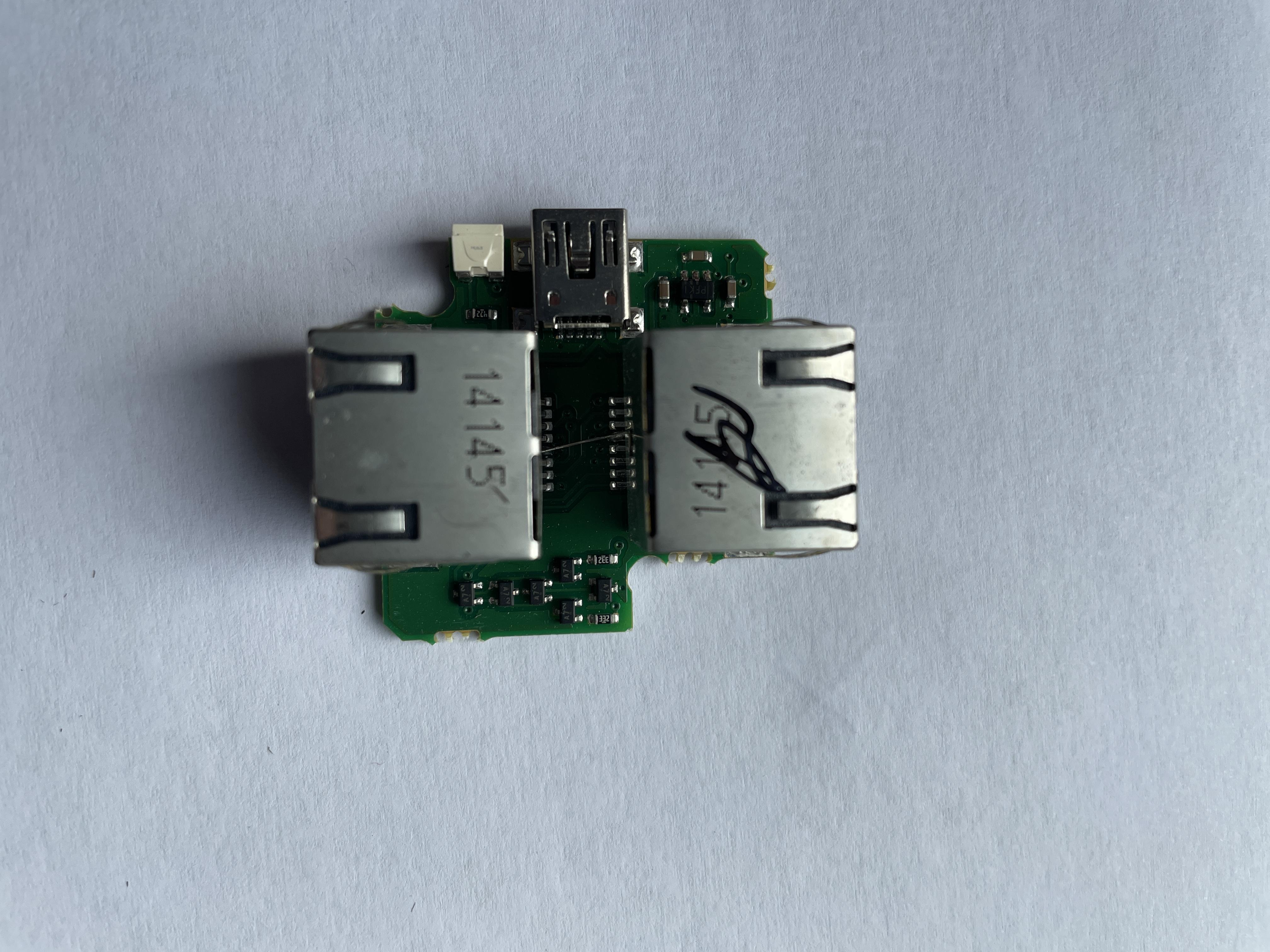
MadskpGOLD MemberInteresting. Roughly what I expected to be in there. The 5-pin chip is an unregulated charge pump used for inverting the + 5V from USB to -5V. The smaller ones on the other side of the board are indeed some diodes and two resistors. They are used for providing power to the data lines.
Ok so if I understand correctly the ML power box only deliver the 0.25/-0.25V for the datalines and not the higher voltages on the pink and blue wires?What could be the reason for not having the supply of the data voltages in the BLC NL/ML? Is it because there can only be one unit providing it in a ML network?Location: Denmark
MadskpGOLD MemberI can try to test it if I can find the time later this weekend
Location: Denmark
MadskpGOLD MemberMadskp, B3OHACK3R, would you believe that a BeoLink Passive provides the required MasterLink voltage (as the 1611 does)? I do have one of those lying around. With two CXs and an IR eye (and a remote) I could maybe also keep the number of sound factory boxes limited to two. Regards, Johan
I would think so as it is a link room product like the BL2000, although it has some converter functions in it
Location: Denmark
MadskpGOLD Memberyes that is the same PCB I have in the Ouverture
Location: Denmark
MadskpGOLD MemberNo flux capacitor! It does have an LED though
 I really cannot tell what the (tiny!) electronics do. If I did not capture a detail that is of use, let me know, and I can try to make a close-up with a camera.
Thanks for the look inside. At least it’s not just an empty box with some wirering from USB to RJ45 😉 but I can be discussed if the components inside reflects the price these boxes are sold at used.
I tried to google the 5 pin IC and it looks like it’s some kind of power regulator
https://www.indiamart.com/proddetail/pfki-24844731397.html
The small 3 legged transistor looking components seems to be some kind of diode
https://www.indiamart.com/proddetail/a7-smd-diode-19562740788.html
Location: Denmark
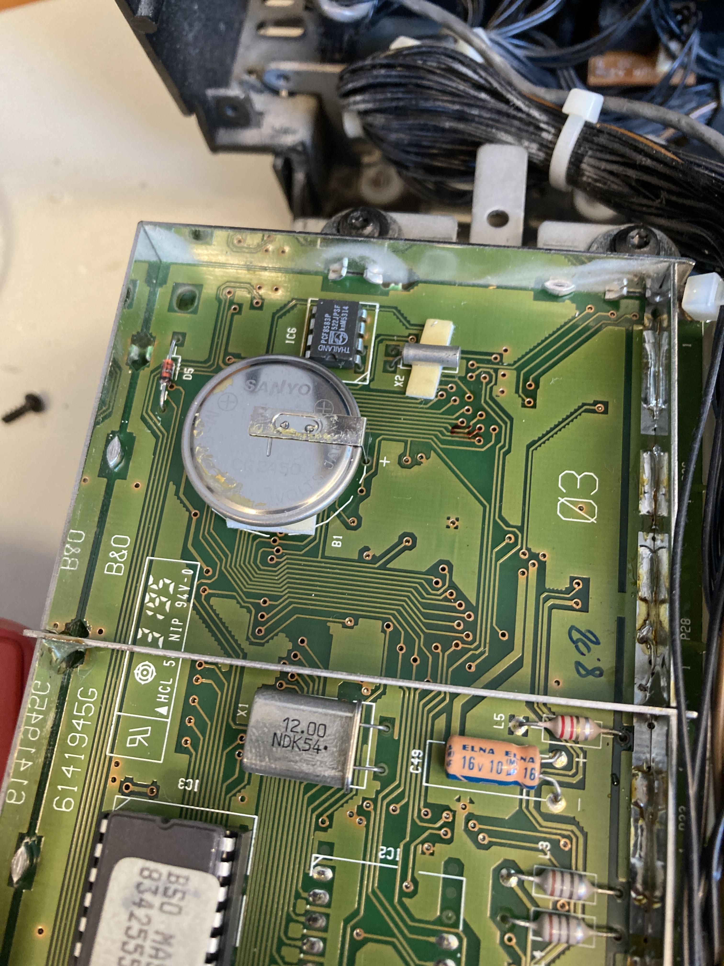
MadskpGOLD MemberI have also checked the battery to see if there should be any leakage.
It looks fine for now, and I meassure a voltage of 2,93V, so not high priority before the othe issue is solved

Location: Denmark
MadskpGOLD MemberGetting back to my Ouverture project I have now per Guy’s suggestion in another thread tried to play a CD which use the full 74 minute playtime. I have played it several times, and the Ouverture can play the whole CD without problems.
The problem that I have to press CD twice to get the CD spinning remains however.
I have tried to reflow alle the new capacitors just in case one of them had a bad connection, but that did not make any difference.
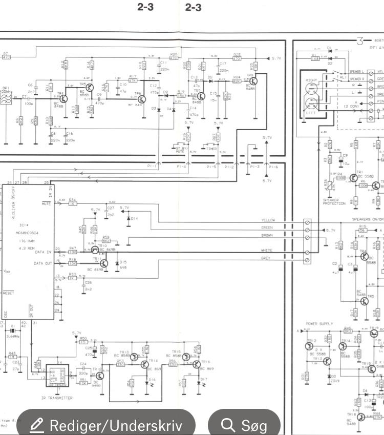
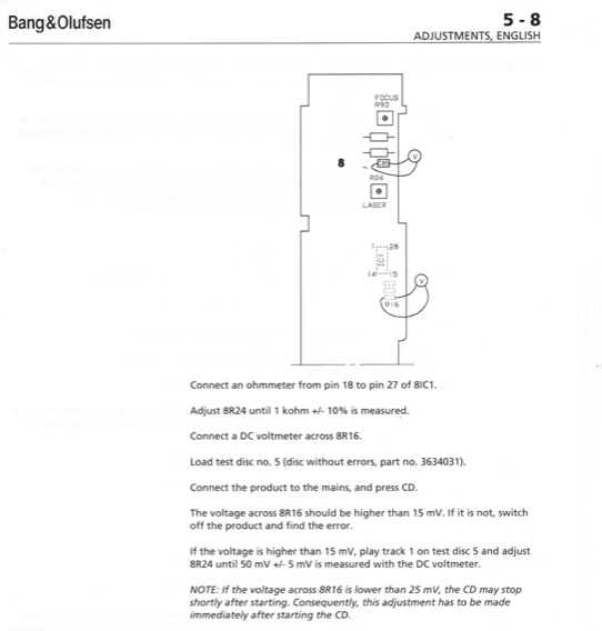
The updated part of the servicemanual for the CDM laser available at Beoworld has this passage which might very well be what I am experiencing:

However section 5 is not in the update for the servicemanual, and the procedure described in the older servicemanual is for a PCB with two trimmer potentiometers which is not on the PCB in my Ouverture

So I wonder if a newer version of section 5 in the servicemanual is available?
Also I would have to get hold of the described test CD to do these adjustments
Location: Denmark
MadskpGOLD MemberYeah those batteries can make a mess.
I don’t know if it is just the picture, but it looks like there is a crack in the diode D5
Location: Denmark
MadskpGOLD MemberWhen you use a computer, phone etc. As an input it is a good idea to set the volume to max. On that device in order to get the strongest line level input signal.
This could be the issue in your case and explain why you have to turn the volume up on the MCL2AV up.hope that helps
Location: Denmark
MadskpGOLD MemberGreat to hear that you got it all working again 🙂
Even though it’s old the MCL2AV is a brilliant and versatile box in my opinion
Location: Denmark
-
AuthorPosts