Forum Replies Created
-
AuthorPosts
-
Madskp
GOLD MemberOn CharlieWednesday saidAhm that makes sense now, thanks. As I said, I’m no electrician! Forgive me though – what is MCL2P?
MCL2P is an anplifier that has powerlink in and passive speaker output, so it can be used for driving passive speakers on anything with powerlink. As it was part of the MCL2 system it also has a 15V power out to power a MCL2AV so you only need one power outlet for using these two units togheter.
Location: Denmark
Madskp
GOLD MemberAn observation with the quote function.
Before the forum was updated it was possible to mark part of a post and press quote and only that part would be inserted in the new post.
Now when you press quote the entire post is quoted which is less optimal if you are trying to answer more than one thing from the original post, or if the original post is a long one
It would be great if it is possible to restore this functionality at some point
Thanks in advance
Location: Denmark
Madskp
GOLD MemberOn Blhu saidHi,
thanks for the response.
Master room equipment is a Beomaster 3300 or the Beomaster 3500.
The Beomaster 3500 will be prefered in a link systems as it does not have the same limitations as mentioned for the Beomaster 3300 above. Furthermore the Beomaster 3500 has the ability to be used in a Masterlink systems by use of a Beolink converter type 1611 or 1612.
i want to hook up my passive ceiling speakers in the outdoor patio and control the volume independent from the master unit. I have on order a Beolink Passive 1656, and I am about to place an eBay order for a IR eye 8089000.
I do have the Beolink MCL2A (transceiver and IR eye)
will the following work:
BM3500 (power link out socket) > power link cable MK2 ->Beolink Passive-> passive speakers.
the IR eye 8089000 will be connected to the Beolink passive for remote control and or manual control.
The IR eye will not work when the Beolink Passive is connected through powerlink. When used with powerlink the Beolink Passive works as an amplifier without volume control (this is done by the connected system) or as a converter from powerlink to drive MCL systems which is not relevant in your case as both your Beomasters has MCL capabilities built in.
Instead you can connect the Beolink passive to Masterlink where it will function as a link room zone with volume control. In order to do that you will need the above mentioned converter type 1611 or 1612.
Beomaster 3500 – 7 Pin Aux cable – Beolink converter 1611/1612 – Masterlink cable – Beolink Passive – Passive speakers
could I alternatively use the IR eye of the MCL2a hooked up to the Beolink Passive to achieve the same. If so is there a color schematic on how to wire the IR from the MCL2a to the 7 pin din. I do need to run the IR cable for about 15 meters to the Beolink passive. Any suggestion on what cable to use for the MCL IR eye. The unit only comes with a short wire.
It is possible yes. I can post the color schematics later. I don’t think the cable needs to be something special, and if you use the MCL IR eye you only need three of the wires. A network cable or a telephone cable might do the job.
Location: Denmark
Madskp
GOLD MemberAs for the damage done by the battery leakage I just gave it a good scrub in first a little white vinegar, and the 99% Isopropanyl alcohol to clean it up (sorry no after pictures)
When I connected the TV again it would still not respond to the remote. Tried starting it up by the App again, which was still working fine. Then just for the sake of it I tried holding down standby on the remote, and the it would turn off.
Still no turning, on, so I tried to set it to V.OPT 1, and bam it worked wit the remote. So might be something to check up on if doing this repair.
I still need to to some of the reassembly, and also maybe try to attach my repair wires more securely to the PCB.
Was it worth the hassle? Well if I had not broke the traces when I cut the super cap it would have been a walk in the park. However as mentioned Jacek1313 the leakage can also affect traces which again will make the repair more difficult. Under all circumstances I will recommend and inspection of the area around the super cap, and if something looks corroded do the cleaning. The affected area might vary depending on which stand is used for the TV.
I will probably do a preventive inspection on my main V1 to see if anything is on the way, and will report back when I have done that.
Location: Denmark
Madskp
GOLD MemberOK this took more time and patience than expected.
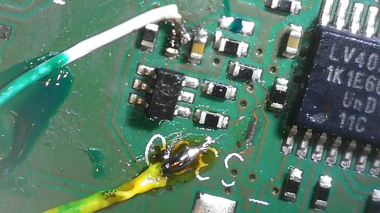
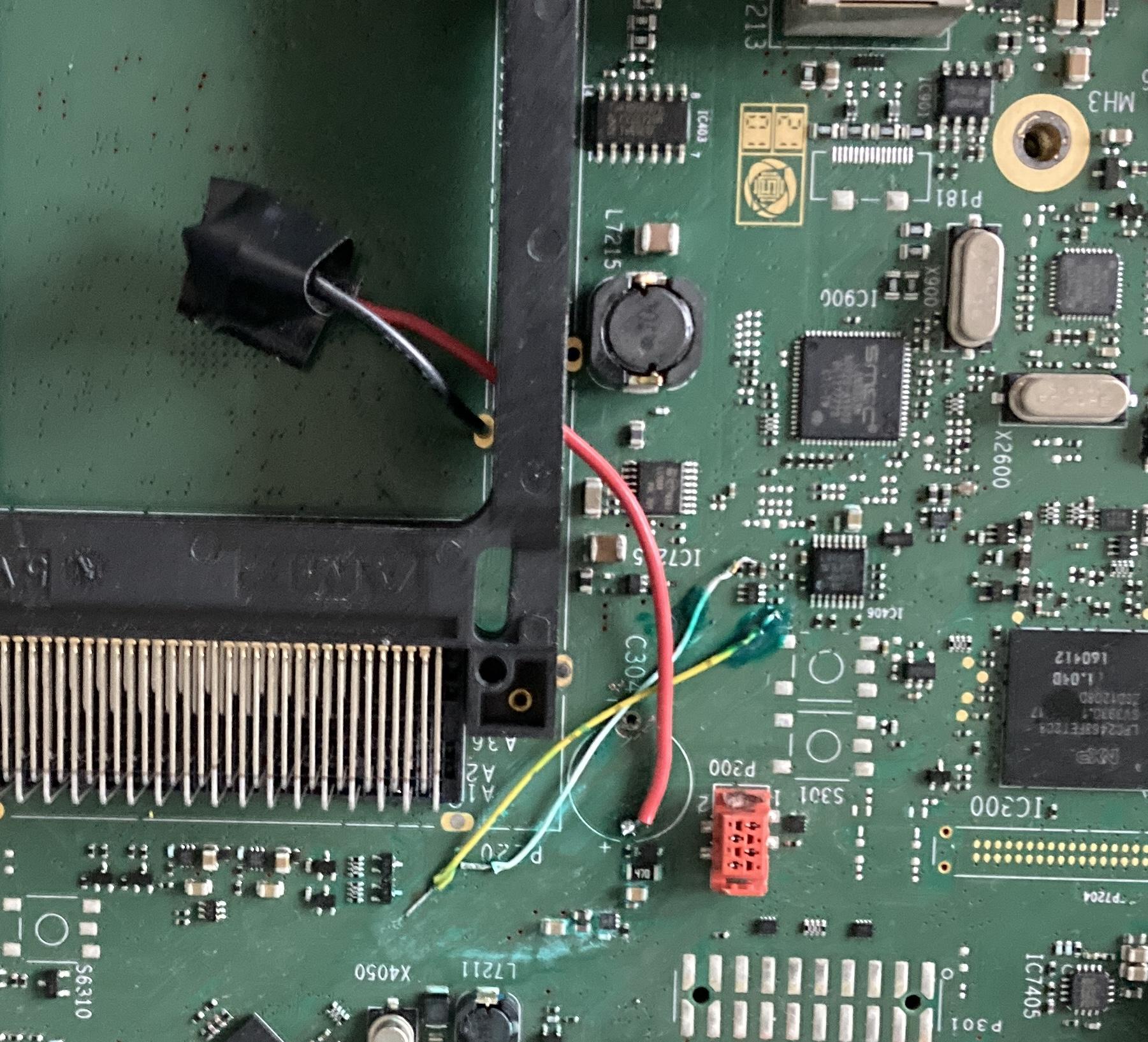
Only 2 of the traces i damaged by removing the battery seemed to have lost connection. My first approch was to just solder a short strain of wire between the two ends of the traces. However that proved to be more difficult than expected as the board seemed to suck the heat from the soldering iron in that area (I suspect a large ground plane in one of the inner layers of the PCB).
Instead I ended up making connection between two places of traces more far away from each other. Still a pain in the **** to do working under microscope with shaking hands, but better results although it does not look pretty.
To connect to the traces I scraped them down with a scalpel, gave them flux and tinned them the best I could. One of the traces ended in a component in one end, so that was far easier to solder to. The other ends was at via’s which I could not loacte on the other side of the PCB.
One of the legs from the old super cap I could not remove, I suspect the issue with getting heat enough was the issue again, so I ended up soldering wires to the PCB and place the new super cap in the common interface slot as I don’t have a need for that. This way the next time it leaks the leakage will hopefull ned in the bottom of the cable compartment where it should no make the same damage.
Location: Denmark
Madskp
GOLD MemberI have used a 15V 400 mA one for my MCL2AV, and that has not caused trouble for me yet. I think that the right polarity has far more concern.
My best guess is that the 250 mA might be a limit for what the MCL2P can deliver if that is used to supply power to the MCL2AV
Location: Denmark
Madskp
GOLD MemberOn Guy saidHere’s the link: https://dk.bosscom.com/products/details?id=1143
Interesting device. The manual does not seem to be available at the page, so I am wondering which remote buttons are used to select the inputs to not interfere with other sources on the Beosystem that it is used with. For BS Ouverture it could make sense with Tape2 and Phono as the Ouverture automatically redirect those commands to it’s AUX connection
Location: Denmark
Madskp
GOLD MemberDon’t know what makes sense with video options other than monitors for retro consoles.
For audio you could hook them up to masterlink with a Beolink Video 1615
Another option for Audio is the MCL2AV which will give you the option to control a datalink compatible Beocord or Beogram/Beogram CD
Location: Denmark
Madskp
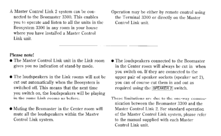
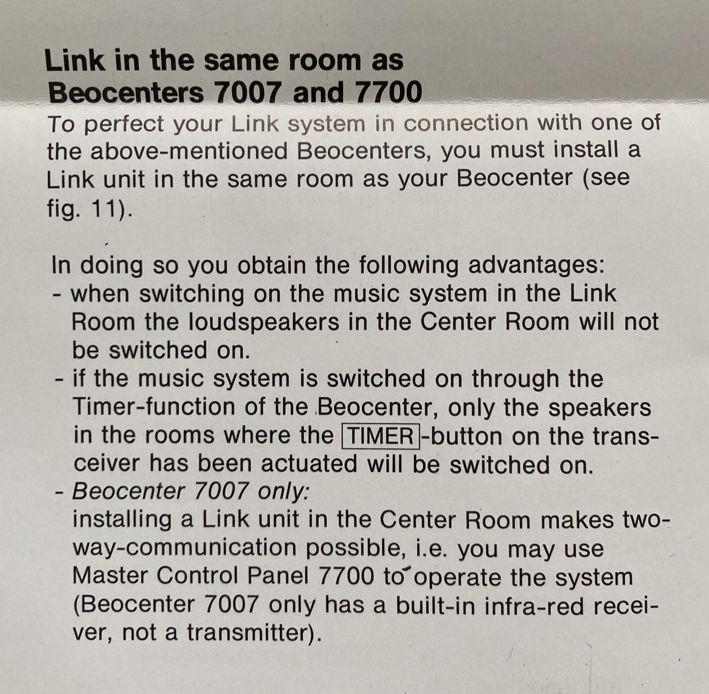
GOLD MemberAn extra note. The BM3300 do have some limitations in regards to muting the sound in the main room. See below:
Location: Denmark
Madskp
GOLD MemberHello
MCL2 is just the naming of this type of link system.
There are three types of compatible link units to use for it:
1. MCL 2A for passive speakers. This is a relative simple unit where you can control the main system. Note that volume control follow each other for the main system and all link rooms with a MCL 2A. The unit consist of a relay box and an IR eye.
2. MCL 2AV for power link speakers. This unit have extra local inputs that can be used in that link room besides the sources from the main room. Also volume control is independent of other link rooms, and to some degree of the main room. The unit consist of a electronics box, an IR eye and a power supply (which might not be included when buying used now). Be avare that the power supply has reversed polarity, so you can not use any power supply that has the sam plug.
Passive speakers can also be connected to the MCL 2AV if a MCL 2P amplifier or a Beolink passive is used in between. A fully wired powerlink cable is needed for this to work.
3. Beolab 3500 MK1 ( up to serial number 19343452). This is a dedicated link room speaker with built in IR eye. Note that if you buy one now it might have been used in a ML system and will need to be setup for MCL2.
For all 3 options you will need MCL cable and 3 pin speaker plugs for connection to the Beomaster.
For the Beolab 3500 an 8 pin DIN has to be soldered to the cable.
Hope this help you. Pleas let me know if you need any elaboration
Location: Denmark
Madskp
GOLD MemberHello and welcome to Beoworld
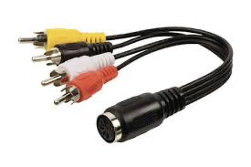
The DIN connectors use one pin for ground, 2 for left and right in 2 for left and right out, and the last two for data communication for control.
Therefor it is possible that the cable you are using is not wire correctly for this usecase.
In cases like this it is often recommended to get a cable like this where you can easily switch to the right pin configuration
Hope this helpsLocation: Denmark
Madskp
GOLD MemberLet me know if there is any information you need, and I can see if it is in the manual and take additional photos
Location: Denmark
Madskp
GOLD MemberI just discovered that I have both the usermanual and the installation manual for MCL82 along with a MCL82 kit in original box. I have not seen these manuals in Beoworlds library or other places online before.
The user manual states that you need an extra MCL82 in the main room if you do not want the main room speakers to play when you activate a link room
The installation manual kinda confirms my suspicion that you need the same remote/Master control panel in the link rooms as in the main rooms
I will try to get a scan of the full user and installation manual when I have acces to an A3 format scanner.
Location: Denmark
Madskp
GOLD MemberOn CharlieWednesday saidYou don’t happen to know if the Beolink converter 1614 is a suitable alternative to the 1611? It certainly looks exactly the same!
The 1614 cant supply the voltage to drive the masterlink network, so for this usecase it wont work. The 1611 will do this.
Location: Denmark
Madskp
GOLD MemberOn Gaea saidI still need a fix for the sticky clamper, there seems to be a fix for it, but I haven’t found it.
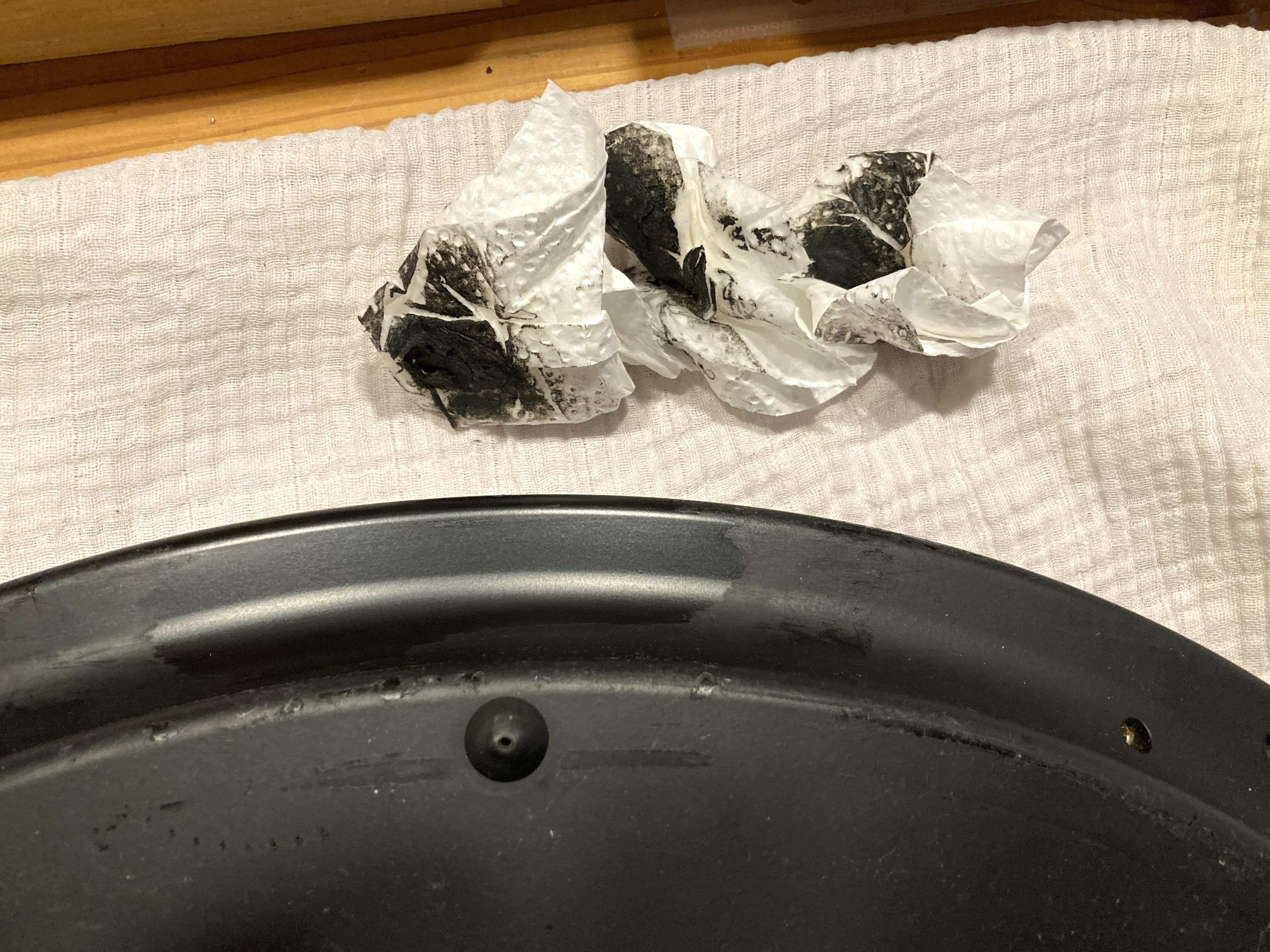
I cleaned the sticky coating on both the clamper and the bottom of the of the BC2 with 99% isopropanyl alcohol. It took a lot of rubbing.
Example from cleaning the bottom here:
Location: Denmark
Madskp
GOLD MemberBe avare that the belt Beoparts are selling is for the wings, and that might solve the problems.
The belt I mention in the thread you are linking to is for the CD clamper, where the issue in my case was that it did not close enough to hold the CD in. This belt however can not be sourced from Beoparts, so I had to find one on Ebay.
Location: Denmark
Madskp
GOLD MemberIf the problem persist with both the 1611 and 1614 converter we can probably rule those out.
I assume you used the same masterlink cable with the BS3000 so this also can be ruled out?
The output from the BC9300 is fully compatible with the converters so this should not be an issue either. The fact that you get a spinning disc confirms that the control signals are passed through the converter.
It is normal that the BC9300 start in muted mode in this setup as it is using speakers not directly connected to it ( this is decided by option 0 )
You mention noise in speakers. Are those connected to the BC9300 or the Beosystem 3?
One thing just to be sure. Is the AUX cable connected to the AUX socket on the BC9300? If you have accedently have put it in one of the powerlink sockets the control functions will probably work, but the sound will not be on the right pins in the connector
Location: Denmark
Madskp
GOLD MemberI am getting a little in doubt if my suggestion will help you. I was under the assumption that the MCL82 kit was controlled only by a terminal 5000 which might be easier to find.
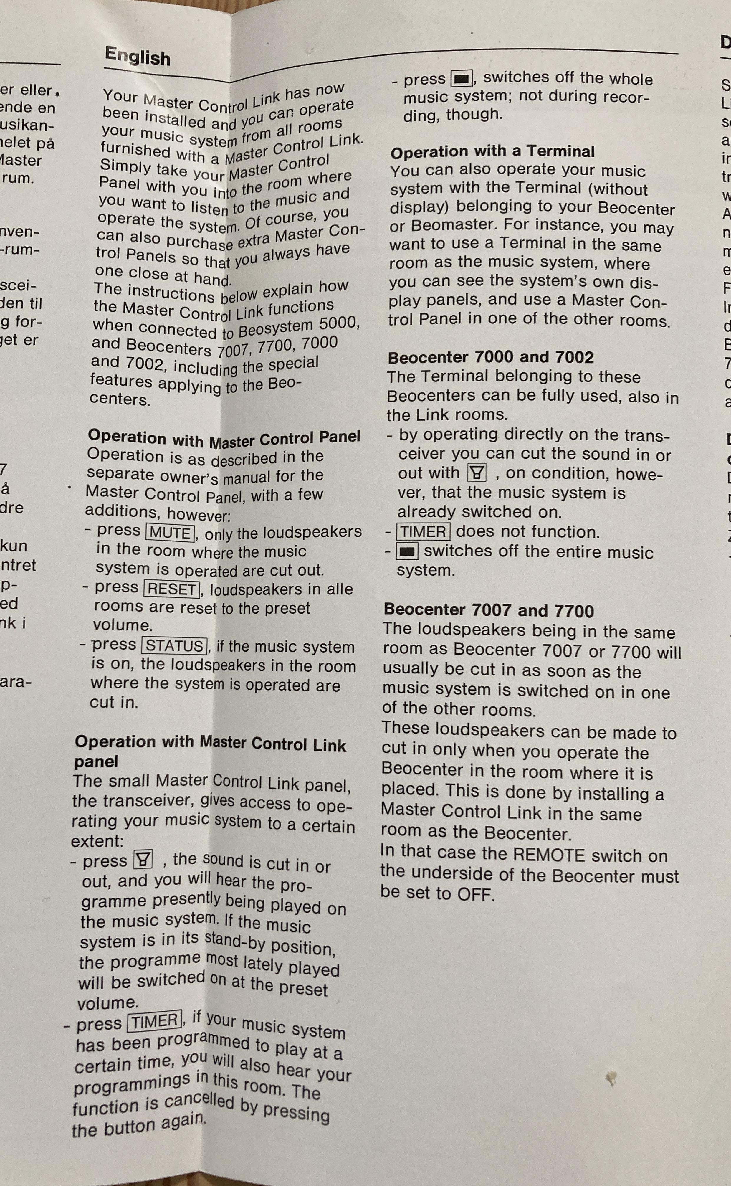
However reading the manual for the Beocenter 7007 it refers to the MCL82 being controlled by the Beocenter terminal and Master Control Panel. I guees that means those for the Beocenter 7007 which does not solve your problem.
I sm wondering if the MCL82 only works with the remotes for the main system they are connected to
Location: Denmark
Madskp
GOLD MemberThis Beotech might answer the question although it is negative.
https://beoworld.org/master-control-link-mcl30-mcl82/
A code converter was available for BM5000, and Beocenter 7700, but that does not help you much.
A possibility that comes to mind is to place a MCL82 link zone in the same room as the BC7007 and connect the speakers to the link box instead of the BC7007.
Hope this give some inspiration for the further procces.
Location: Denmark
Madskp
GOLD MemberOn mdonald said@Guy, to check the cable I looked at Beotech, is the “Aux Link cable” correct?
That is the right one yes. Basicaly its pin1 to pin 1, pin 2 to pin 2 etc.
Not all pins are needed, but for your setup you will need t least pin 1, 2, 4 and 6 to be connected
Location: Denmark
-
AuthorPosts

