
Forum Replies Created
-
AuthorPosts
-
 BRONZE Member
Solution / cause found
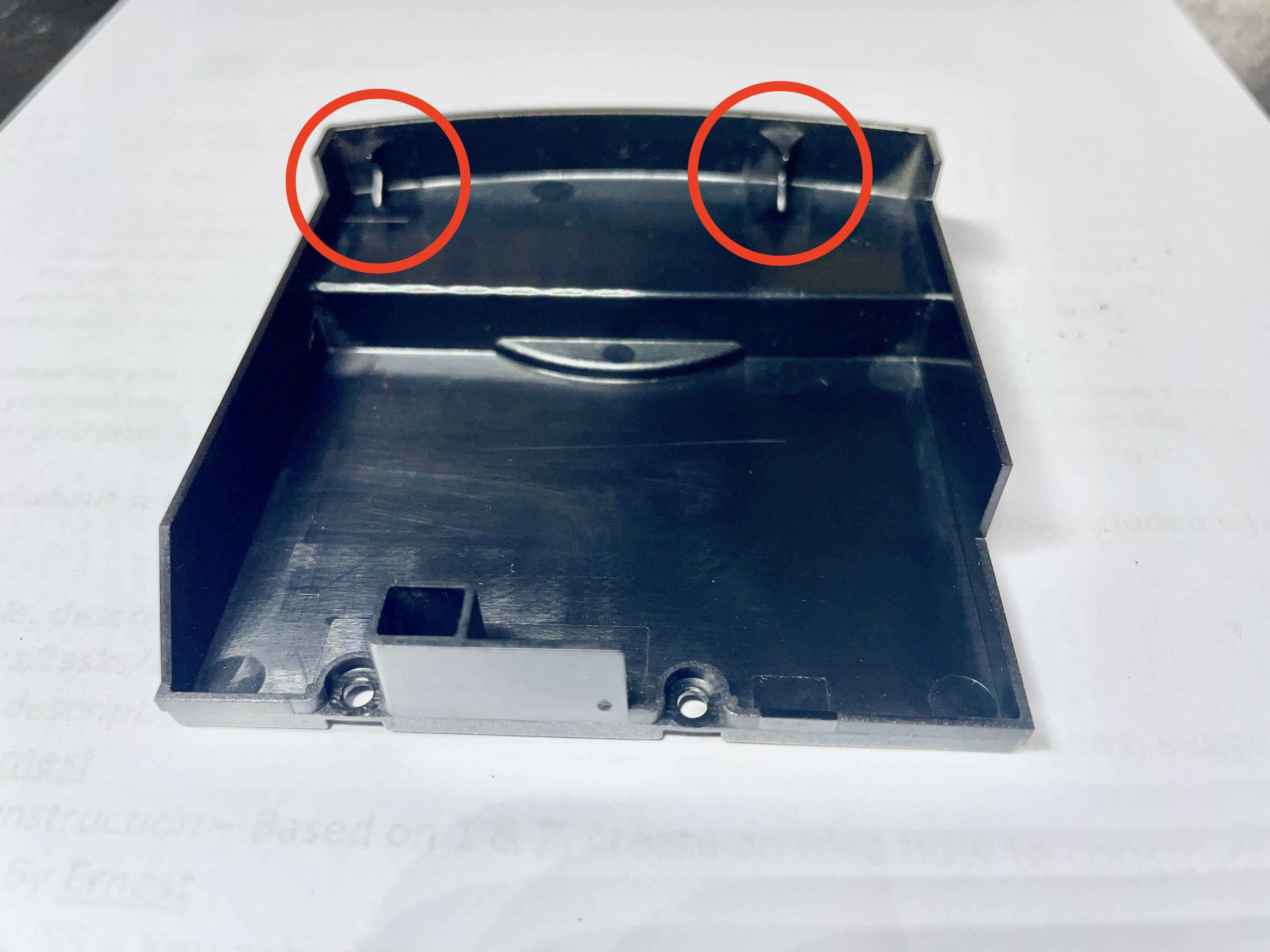
The issue was caused by the left cover panel of the sledge. After re-assembling it, I did not put it back the right way. Causing it to be too high to make the sledge move all the way to the end at the 6th disc.
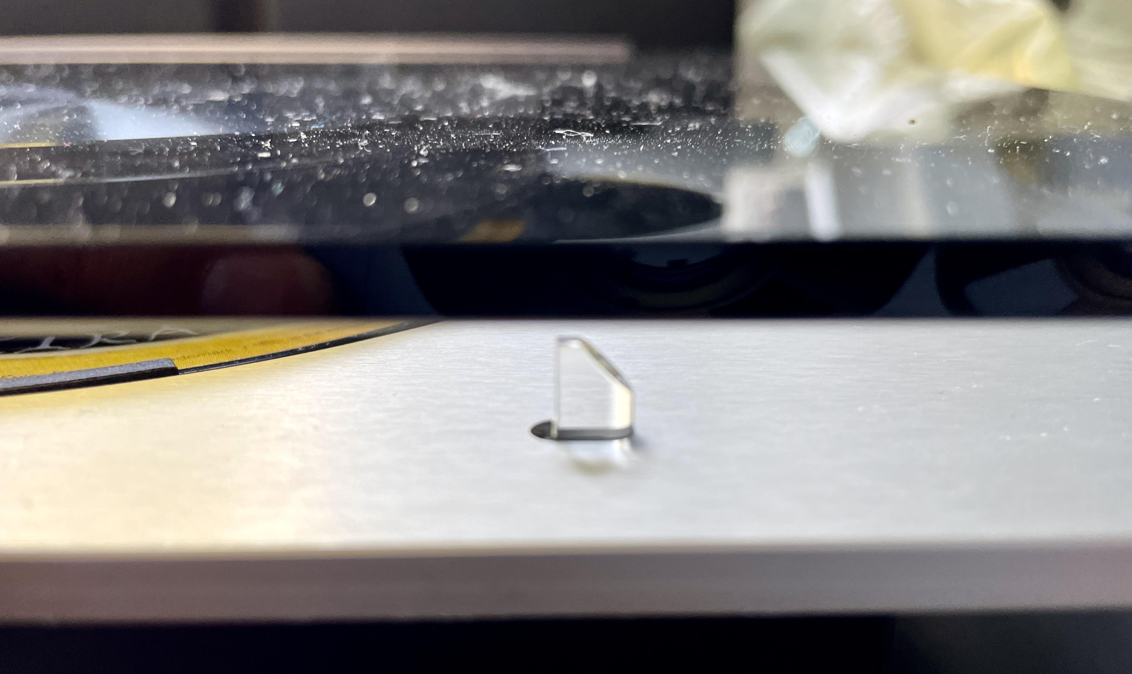
This cover panel has two clamps (see picture) that need to grasp on the edge of the PCB that it covers. If they are positioned right, everything fits well and the sledge can make the normal movements.My advise for re-assembling after working on the BS9000 laser unit is to put this cover back, and then immediately hand-move the sledge all the way left and right (while the sledge is still unblocked). This prevents that you find out later and you have to disassemble and re-assemble again.

Location: The Netherlands
Favourite Product: BeoSound 9000
My B&O Icons:

Thnx @Matador !
You are referring to the “orange part in the picture”.
Do you mean the orange PCB and its flatcable?
Location: The Netherlands
Favourite Product: BeoSound 9000
My B&O Icons:
I have disassembled the laser/lens/mirror unit, and did a cleaning according to the instructions by japcast in his video on Youtube. By the way, this is a great instruction video!
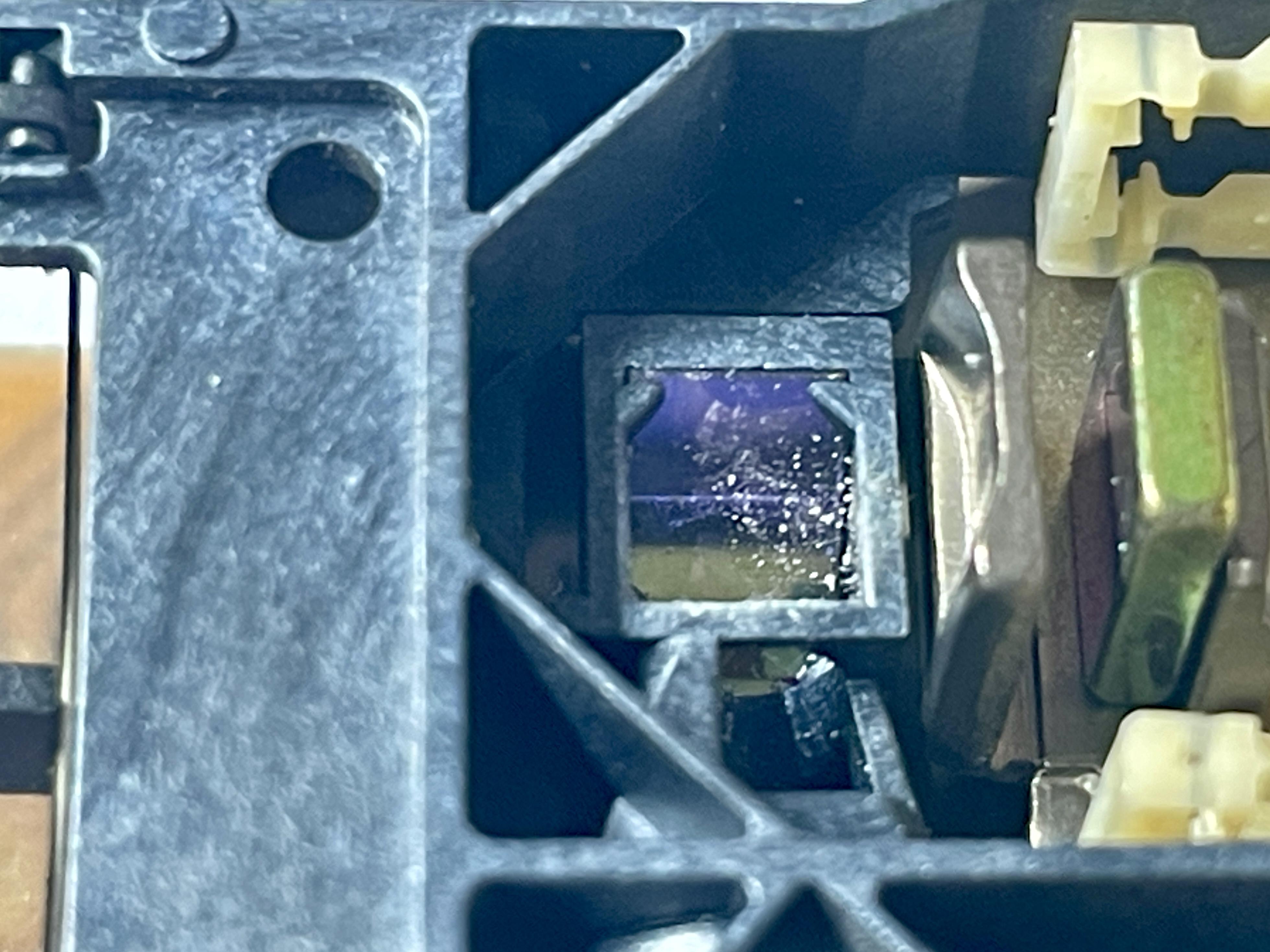
I did find after disassembly and uncovering the mirror, that it was very dirty. Look for yourself:

After cleaning and re-assembly I did a CD play test, unfortunately with still the same error as when I started.
After that I did a TestMode run #27 again. Interestingly with some different results than when I did this run before cleaning. Here’s the differences:
Before cleaning:
- NO ML ERROR
- 1 IIC ERR104 = The 35IC2 motor processor
- 1 CD ERR 2 = Focus error, it has not been possible to find focus.
- NO SER ERROR
- 1 SLG ERR 31 = microprocessor 35IC2 cannot register pulses from 9PE1.
- NO PLT ERROR
- 1 APS ERROR 15 = it has taken more than 5 seconds to carry out auto positioning. The turntable motor driver might be defective.
After cleaning:- NO ML ERROR
- NO IIC ERR
- 1 CD ERR 2 = Focus error, it has not been possible to find focus.
- NO SER ERROR
- NO SLG ERR
- NO PLT ERROR
- NO APS ERROR
So, it’s positive that most errors are gone. Though a pity that it still doesn’t play.
My questions
- I guess there is only one thing left; replacing the laser/lens/mirror unit. Correct, or are there still other possibilities?
- If I need to order a replacement laser/lens/mirror unit, where can I find it? And where can I trust it is the right one and working? (I need it for a BS9000 MK2, type 2561)
Location: The Netherlands
Favourite Product: BeoSound 9000
My B&O Icons:
I have come to the point that I have disassembled enough to have full access to the laser unit.
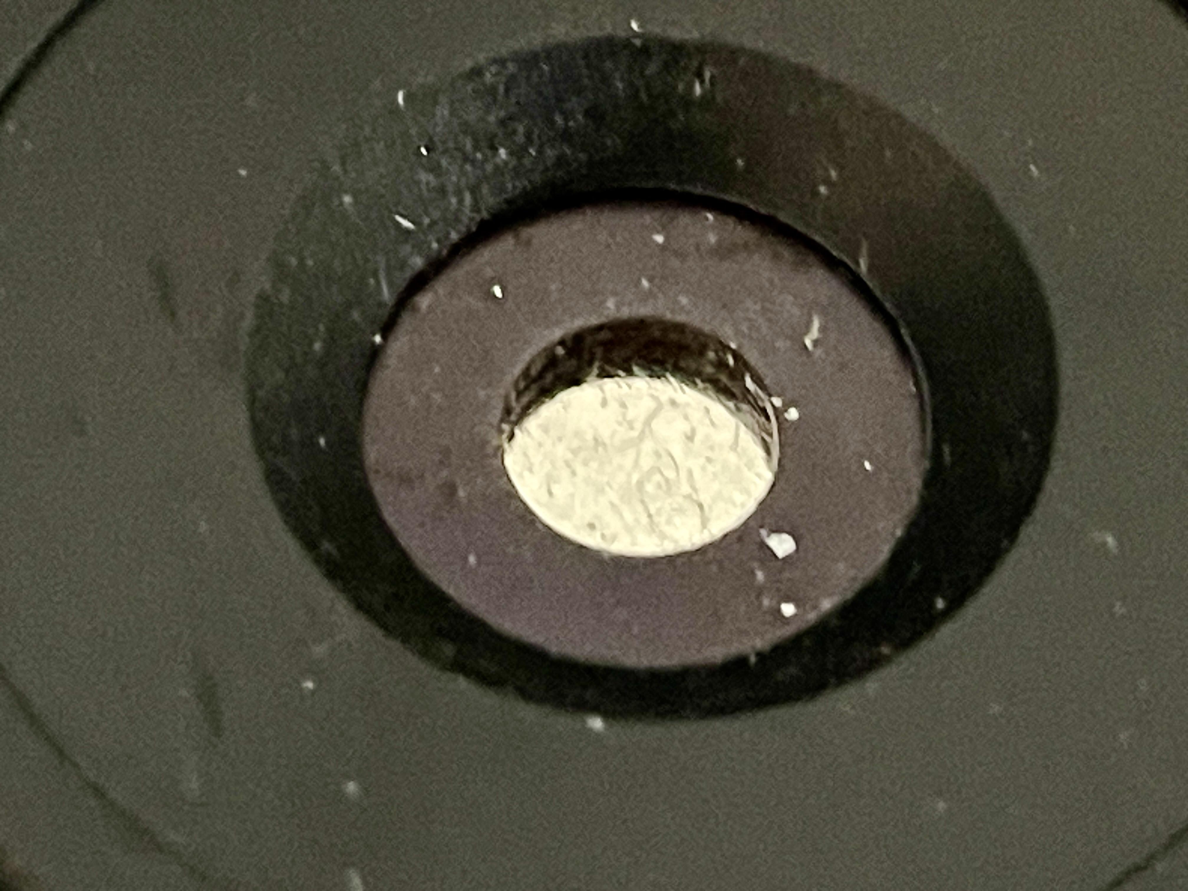
What I noticed is this part …
The middle:
The outer ring:

Question 1
It is very dirty. I think this is just the clamp and the dirt does not affect the laser/reading of the disc. Is that right?Laser unit
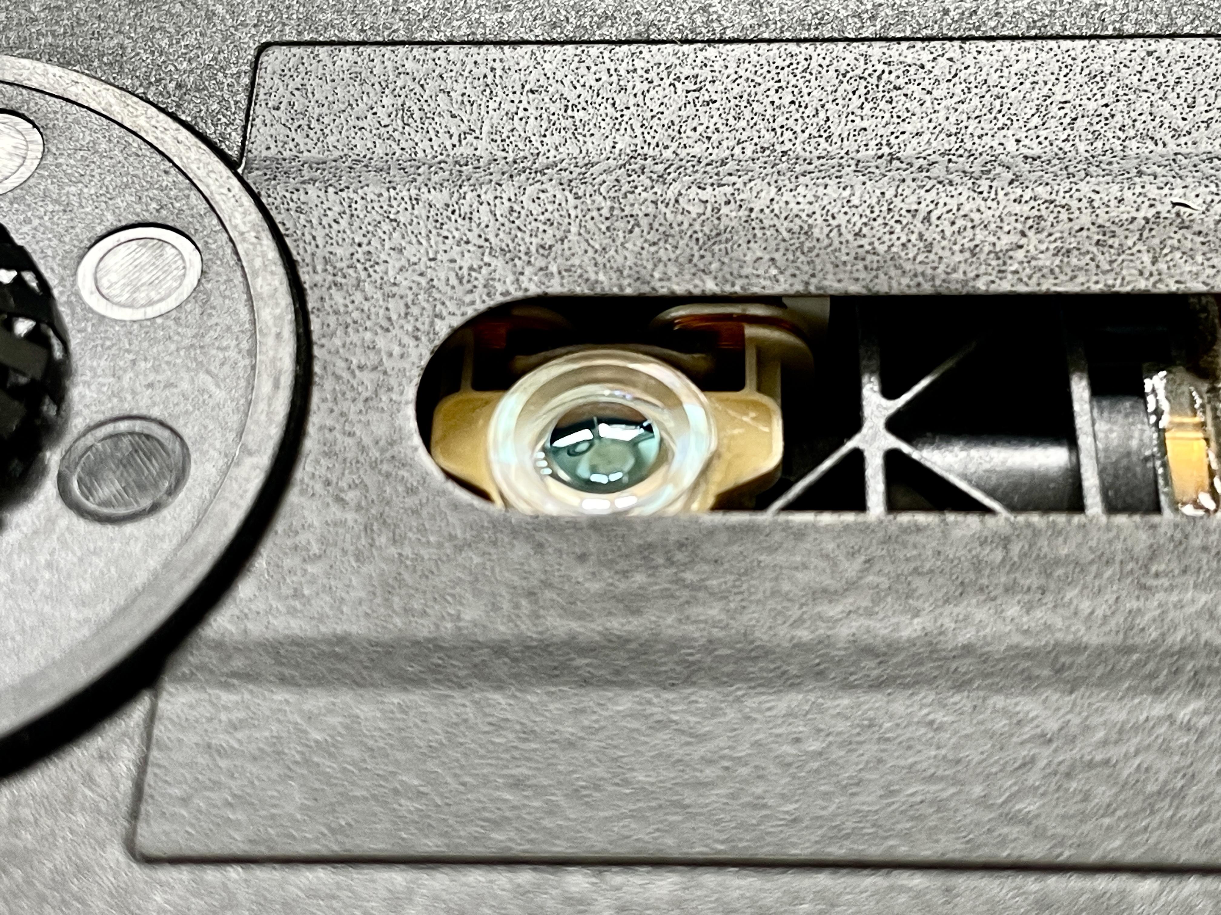
I have uncovered the laserunit. What I can see is the lens, which I will clean with isopropyl.Question 2
Besides cleaning the lens here, is there anything else I should clean?Location: The Netherlands
Favourite Product: BeoSound 9000
My B&O Icons:
Thnx @Matador !
It’s also my guess that the laserunit needs replacement.
Question
- Is there any other test run I can make in Test Mode, to confirm that?
- Do you know any reliable source to order the right replacement part for this BS9000 MK1 type 2561?
Location: The Netherlands
Favourite Product: BeoSound 9000
My B&O Icons:
Thnx @Pestria !
Since I am new to the BS9000, where can I find the two sensors you talk about?
Are these like this (see picture below)?
But I guess the sensors themselves are underneath?

Location: The Netherlands
Favourite Product: BeoSound 9000
My B&O Icons:
Hi @LPCOLLECT.
I am having the same issue here with a BS9000 type 2561, I believe that’s a Mark II.
Did you find any solution solving your issue?
Location: The Netherlands
Favourite Product: BeoSound 9000
My B&O Icons:
What input do you use: PowerLink or RCA?
Location: The Netherlands
Favourite Product: BeoSound 9000
My B&O Icons:
I have had experience with rubber rings letting loose once before. Most common causes for that:
– The glue used us a bit old and therefor dried out.
– The adhesion pressing after glueing has not been done enough.
After having done a lot of refoaming, I can conclude that it is a reliable way of repairing/restoring speaker drivers. Nevertheless, the execution has to be done accurately.
Location: The Netherlands
Favourite Product: BeoSound 9000
My B&O Icons:
13 February 2024 at 11:24 in reply to: BeoLab 3500: sometimes responds to remote control, sometimes it doesn’t ? #52574Thanks for all your help B3OHACK3R !
I couldn’t have don it without. 🙂
Location: The Netherlands
Favourite Product: BeoSound 9000
My B&O Icons:
12 February 2024 at 16:44 in reply to: BeoLab 3500: sometimes responds to remote control, sometimes it doesn’t ? #52572Another and final update.
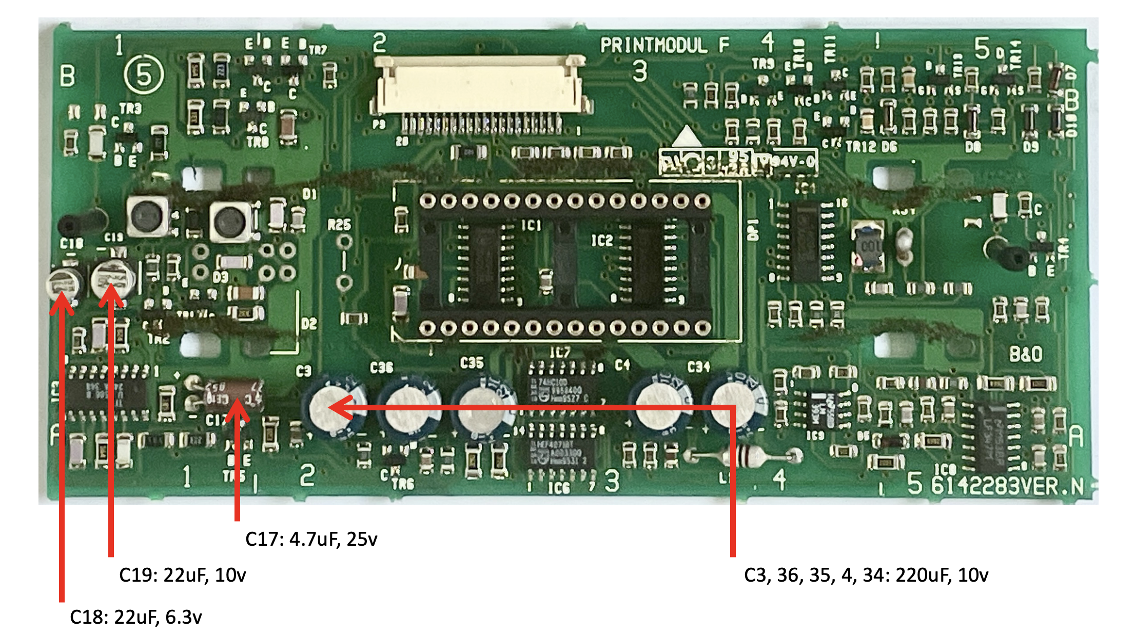
I have just replaced the capacitors C18, 19 and 17. After removing C17 and measuring its values on my capacitor tester, I noticed it was still ok. But anyhow while doing, I replaced it with a new one.
C18 & 19 I replaced with regular electrolytic capacitors. The voltage a bit higher than spec. but still small enough to fit.
Result after testing
Everything works fine again!
Like always, you need to know what you are doing. But this appeared to be very do-able.
For anyone else who needs to do the same. Here are some helpful steps.
Step 1 – Shift the two speaker covers from the middle to each respective side: appr. 1 cm. This will show the two black screws left and right in the middle. Removing those two screws will enable the IR-cover to be removed.
Step 2 – Next the two ribbon panels above and under the IR-panel have to be removed. Each has two light silver screws. Remove them and remove both panels.
Step 3 – On the top of the PCB, just slightly left from the middle, is a flat cable and its connector on the board. Push the two lock sliders on the side of the connector up to unlock it. Gently and evenly, pull the flat cable out. The whole PCB can now be lifted out.
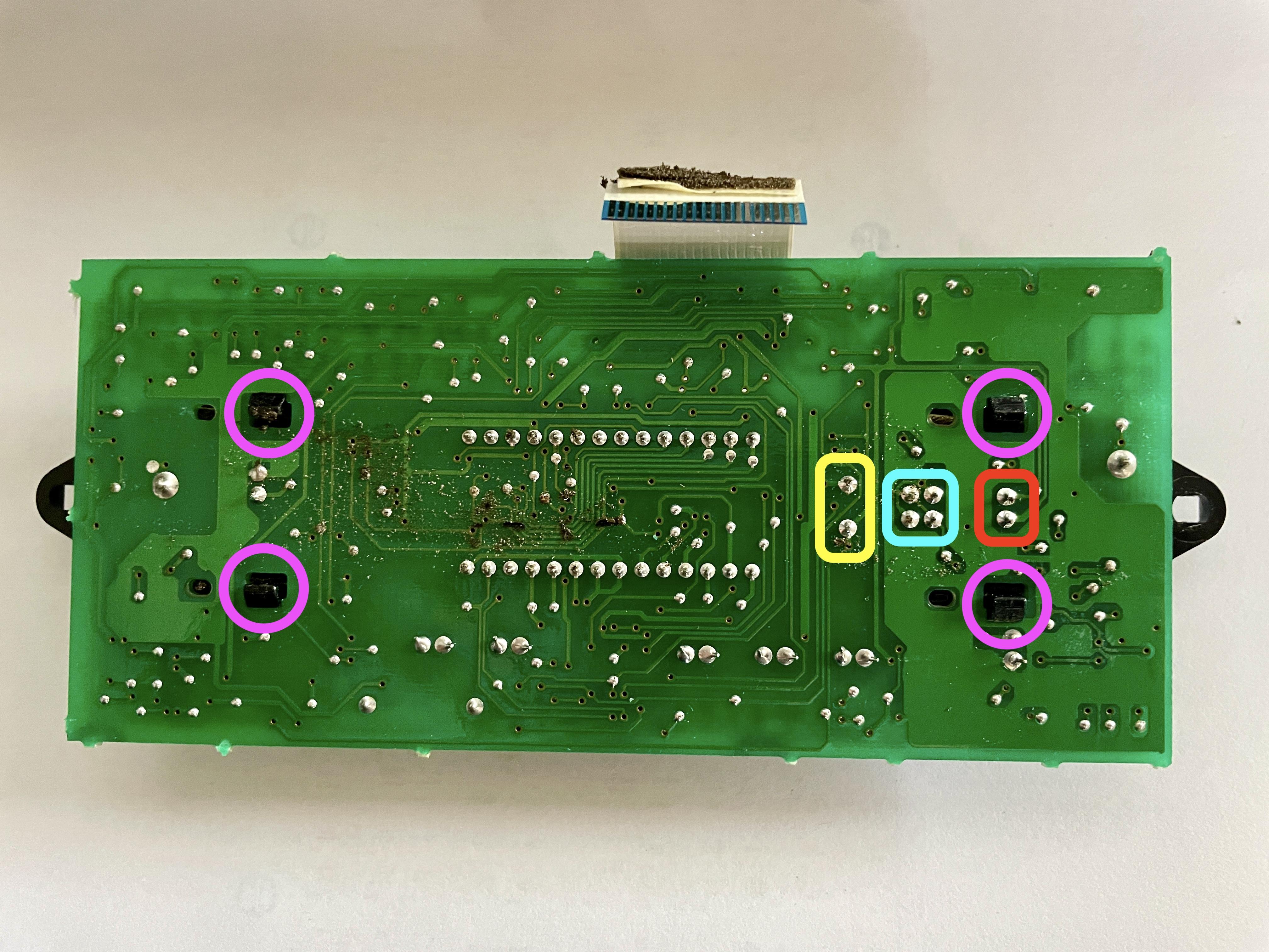
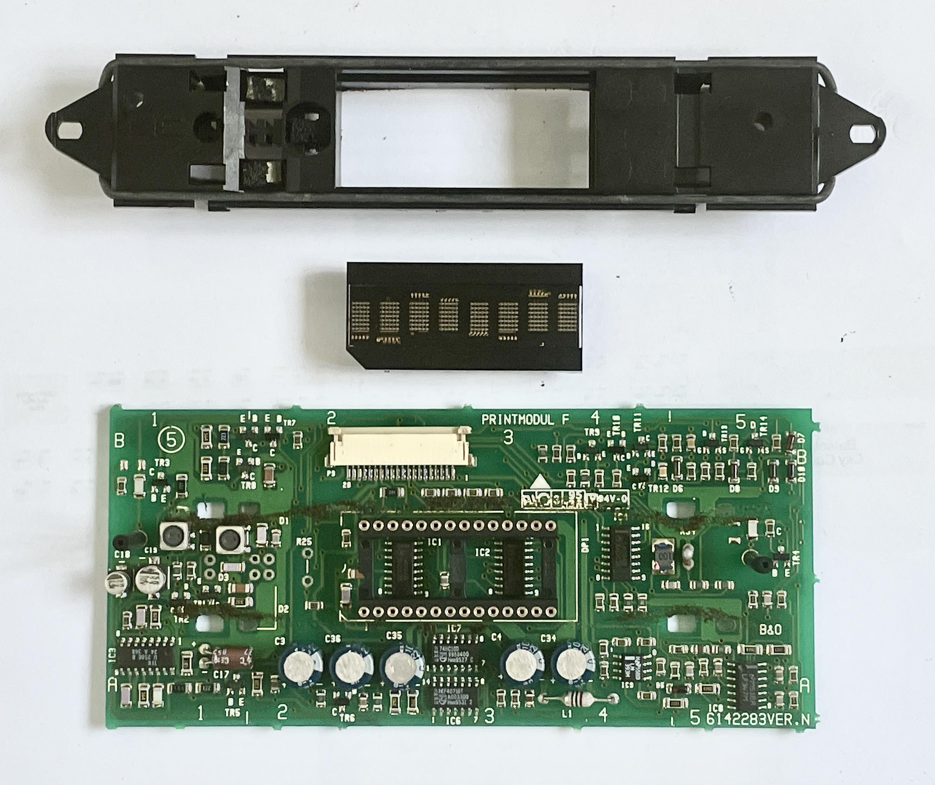
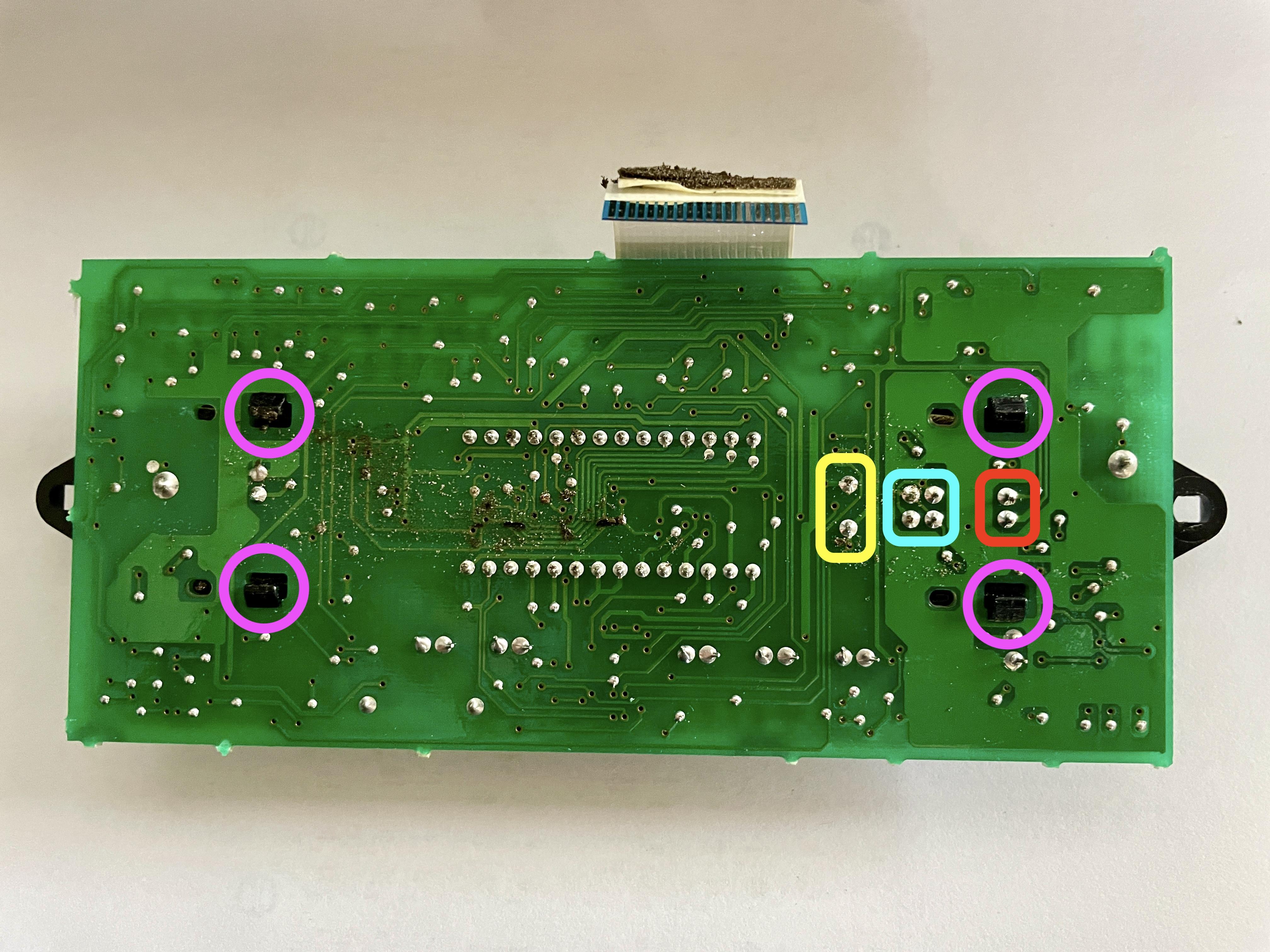
Step 4 – To whole plastic panel that sits on the PCB has to be removed, to get access to the components underneath. To do so, four components have to be de-soldered:
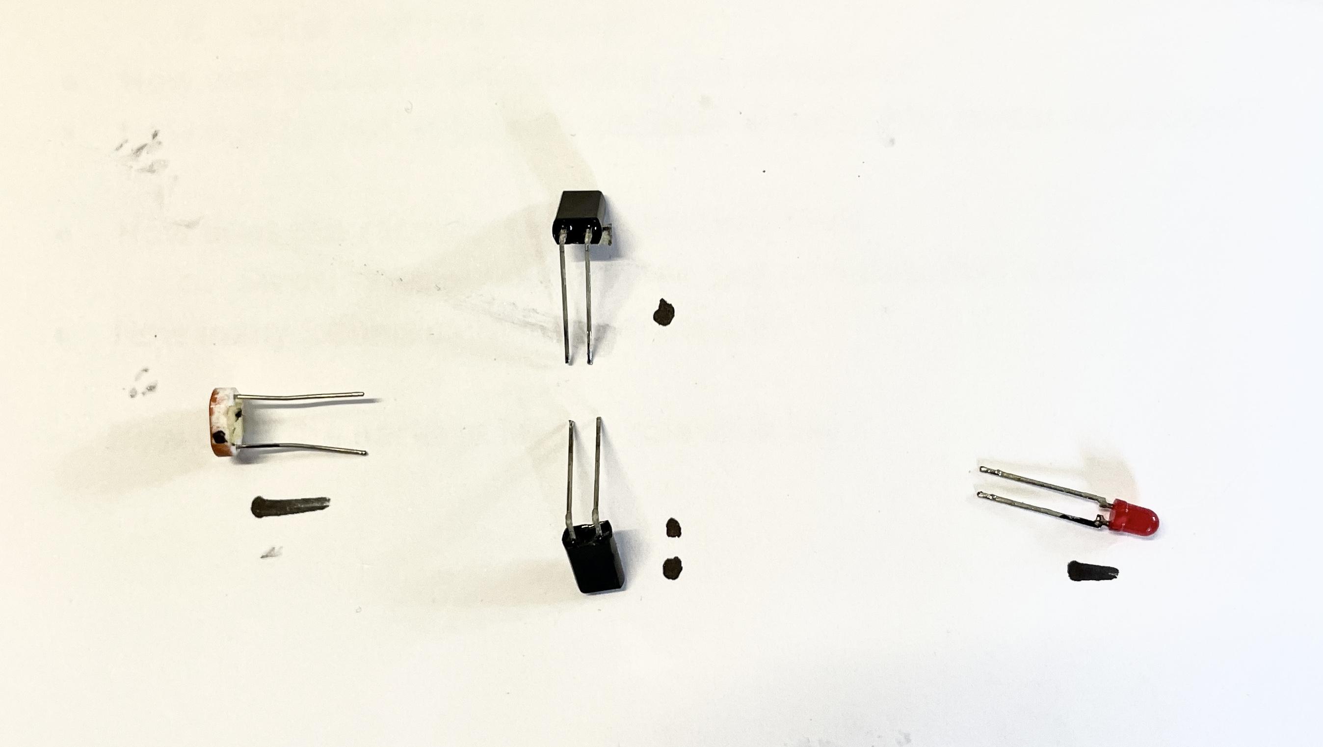
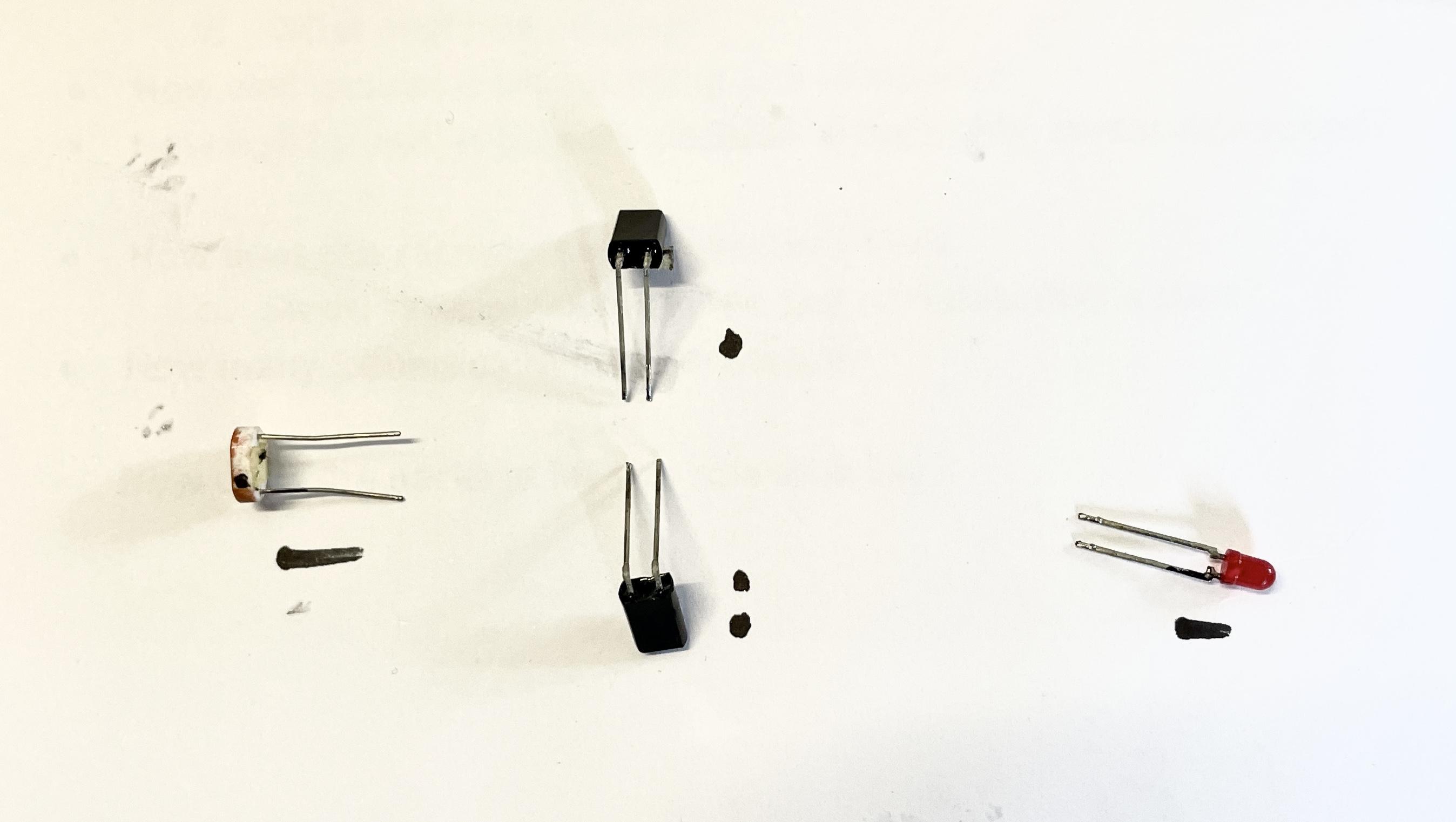
a. Yellow = the red LED.
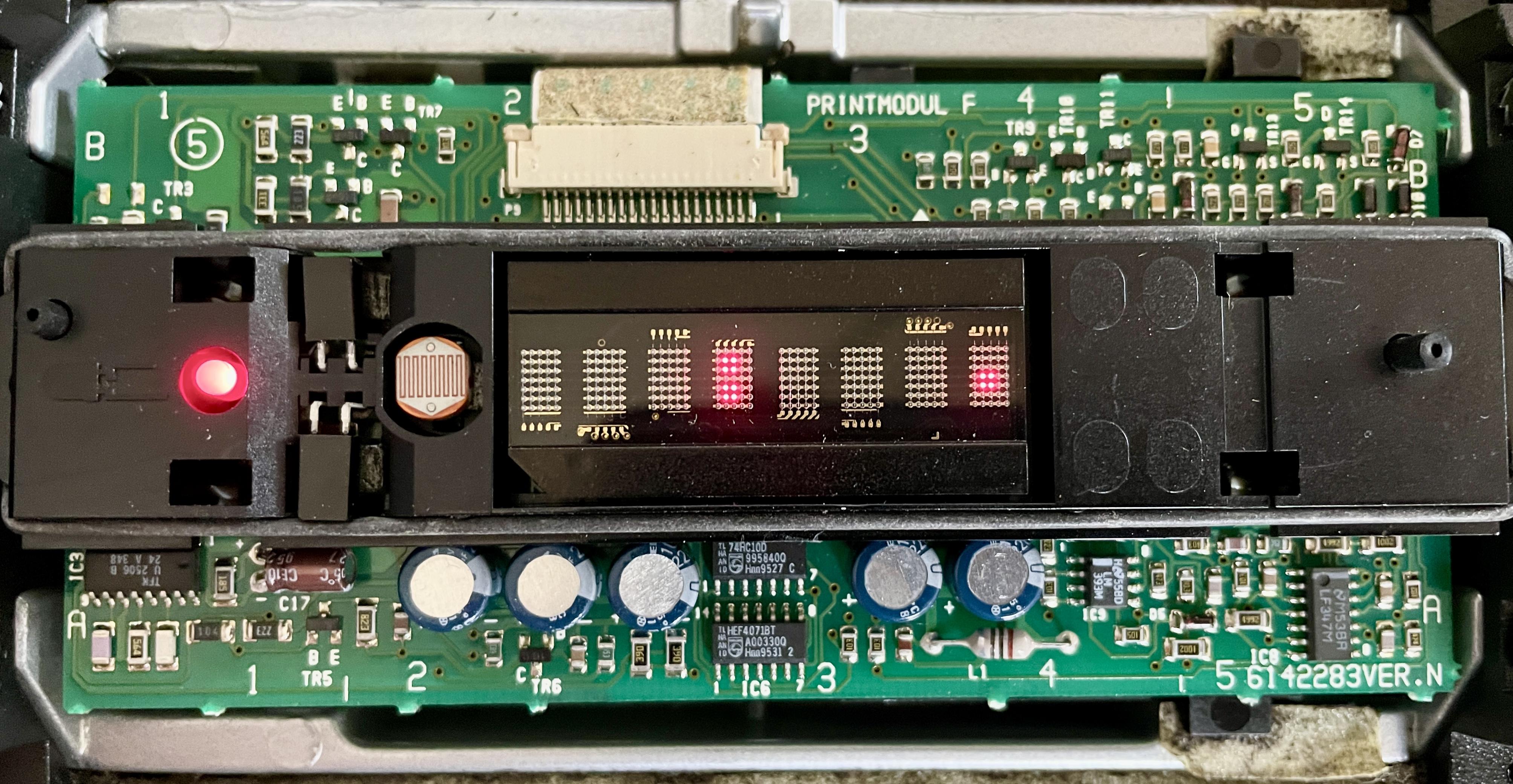
b. Blue = the two IR-sensors. The two top pins for the top sensor, the two bottom pins for the bottom sensor.
c. Red = for the light sensor.
d. Purple = push the clips (two-by-two) inwards to release the plastic panel from the board.Att! Be aware of the position of the components and their legs, removing them. When re-soldering them, the position of the legs has to be right. I marked them both on paper and a leg.

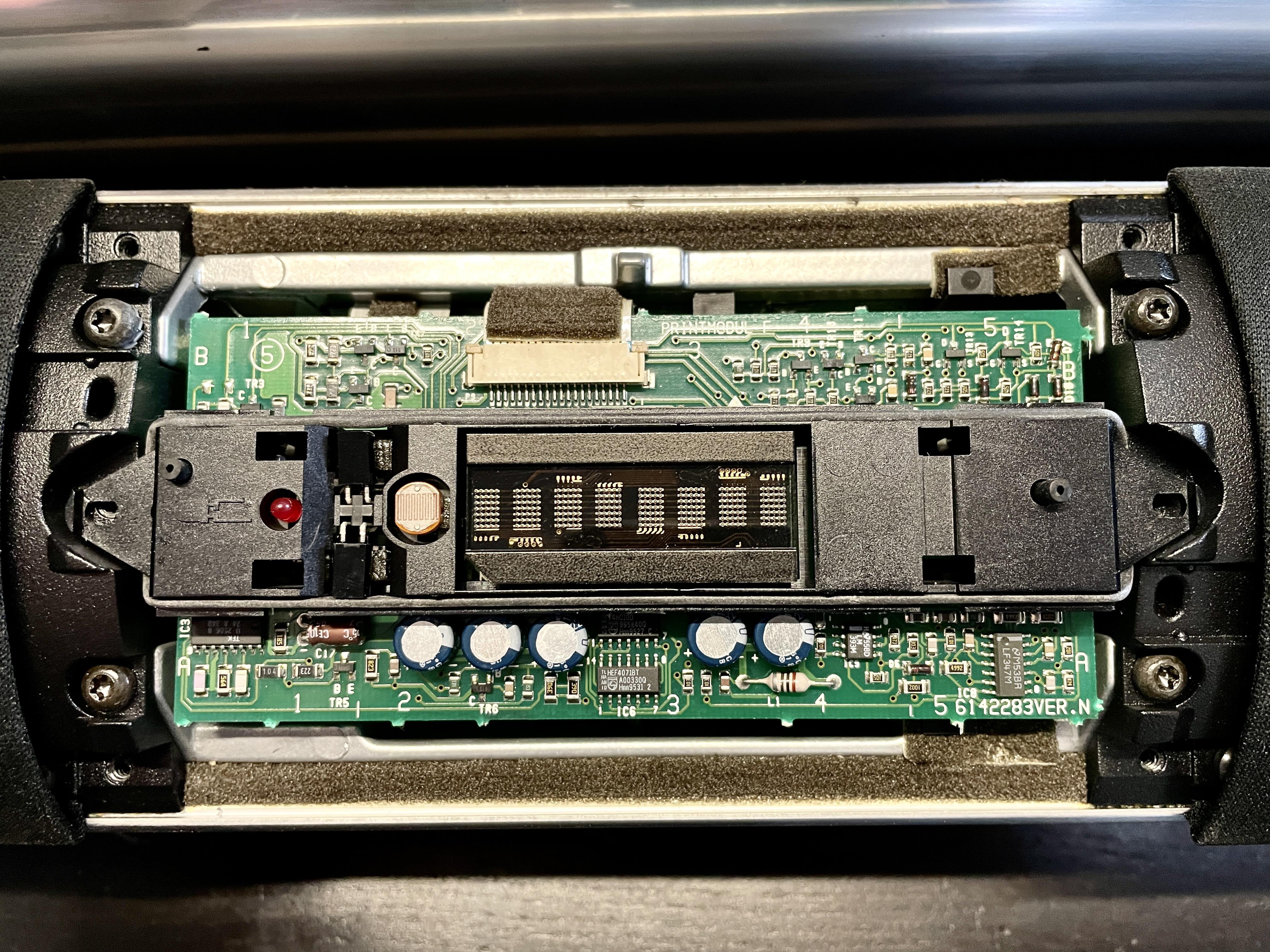
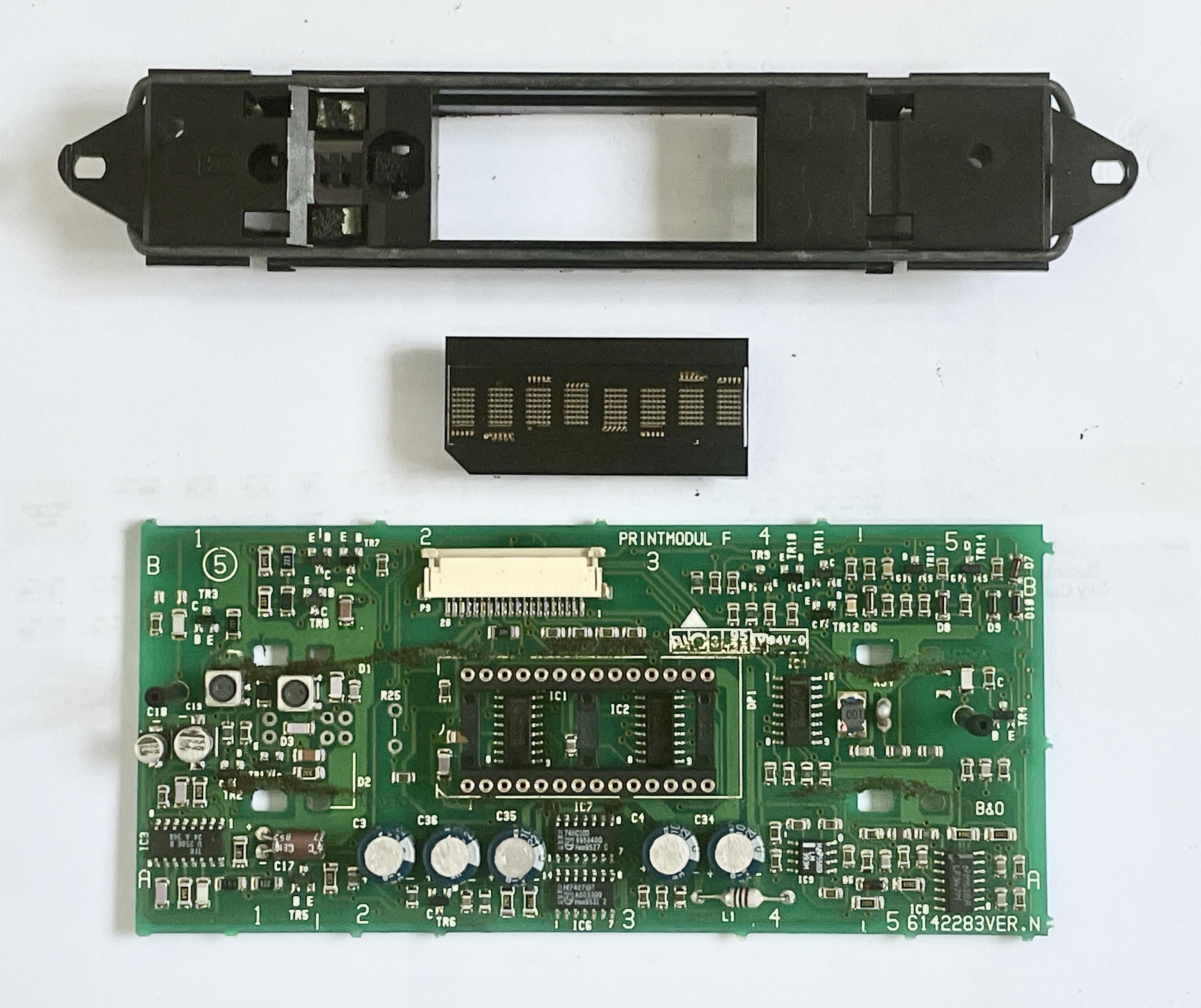
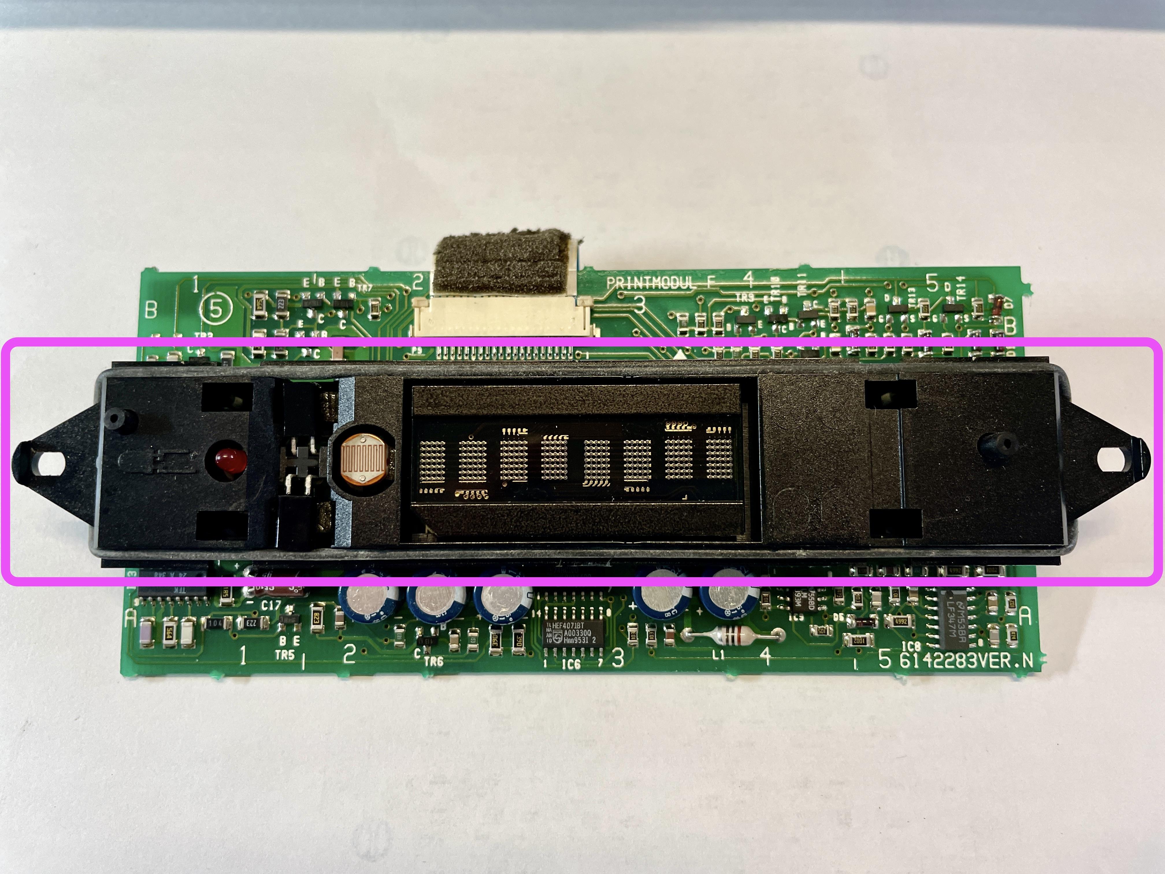
Be aware that to separate the panel from the PCB, some force is needed. Make sure to push/lift the panel even and in a horizontal movement upwards. The display module (block in the middle of the picture below) has two rows of 12 and (resp.) 14 pins. When the panel has been lifted off, the LCD module may come loose. Be aware of its position, especially the cut corner on the left bottom side.

Capacitor replacement
For solving the IR-issue, capacitors C17, C18 & C19 will have to be replaced.
After the replacement, just work in the opposite order as described above.
It makes sense to first reassemble the PCB with its plastic bracket, the LCD module, and putting back the light & IR sensors and the red LED.
Then connect the flat cable and make a test.
If right, everything else can be put together again.
Location: The Netherlands
Favourite Product: BeoSound 9000
My B&O Icons:
12 February 2024 at 13:22 in reply to: BeoLab 3500: sometimes responds to remote control, sometimes it doesn’t ? #52571Great & thanks!
I will now first get the components for C18, 19 & 17 and replace them.
And then make a test.To be continued …
Location: The Netherlands
Favourite Product: BeoSound 9000
My B&O Icons:
12 February 2024 at 13:13 in reply to: BeoLab 3500: sometimes responds to remote control, sometimes it doesn’t ? #52569Update
I have now de-soldered the light and IR-sensors and the LED. I took pictures and marked the legs to remember their position on the PCB.
Pulling the plastic panel from the PCB, indeed needed some force. But for anyone doing the same, be careful to lift the panel in an even, horizontal movement. Especially for the LCD-block in the middle; it sits with 26 pins in a foot socket on the PCB. So this way you can keep the legs all straight.
Replacing capacitors
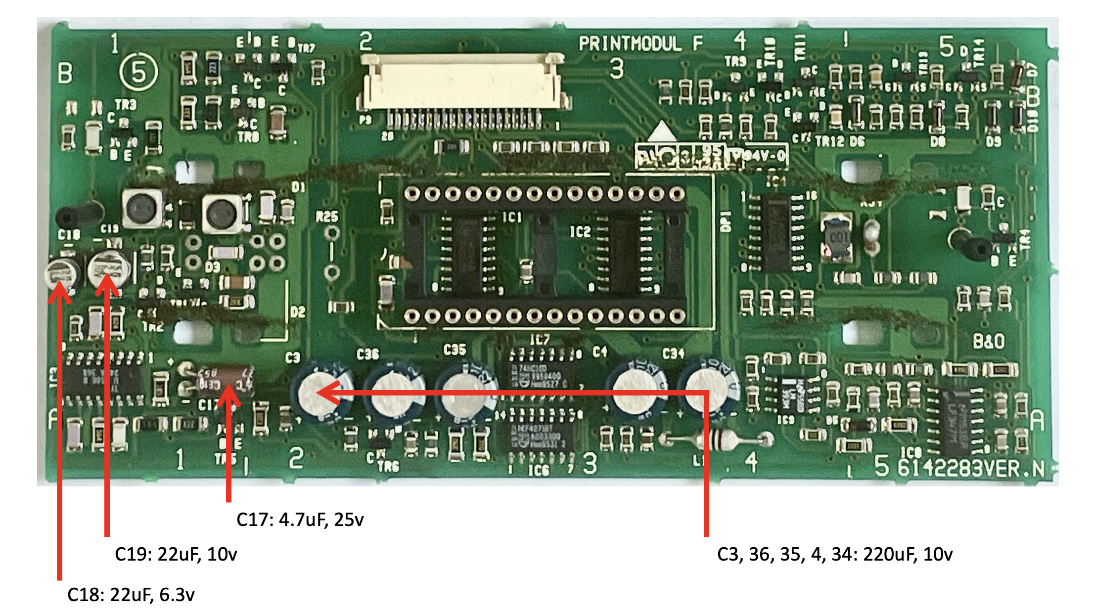
I found these capacitors on the PCB:
Questions
- If I understand wel, C18, 19 and 17 will have to be replaced, right?
- C3, 36, 35, 4 and 34 can stay in place?
Location: The Netherlands
Favourite Product: BeoSound 9000
My B&O Icons:
10 February 2024 at 15:25 in reply to: BeoLab 3500: sometimes responds to remote control, sometimes it doesn’t ? #52568Ok, thanks @B3OHACK3R !
In that case I will proceed with what you advised me to with exchanging components on the board.
Will be continued …
Location: The Netherlands
Favourite Product: BeoSound 9000
My B&O Icons:
9 February 2024 at 14:07 in reply to: BeoLab 3500: sometimes responds to remote control, sometimes it doesn’t ? #52566Here’s an update.
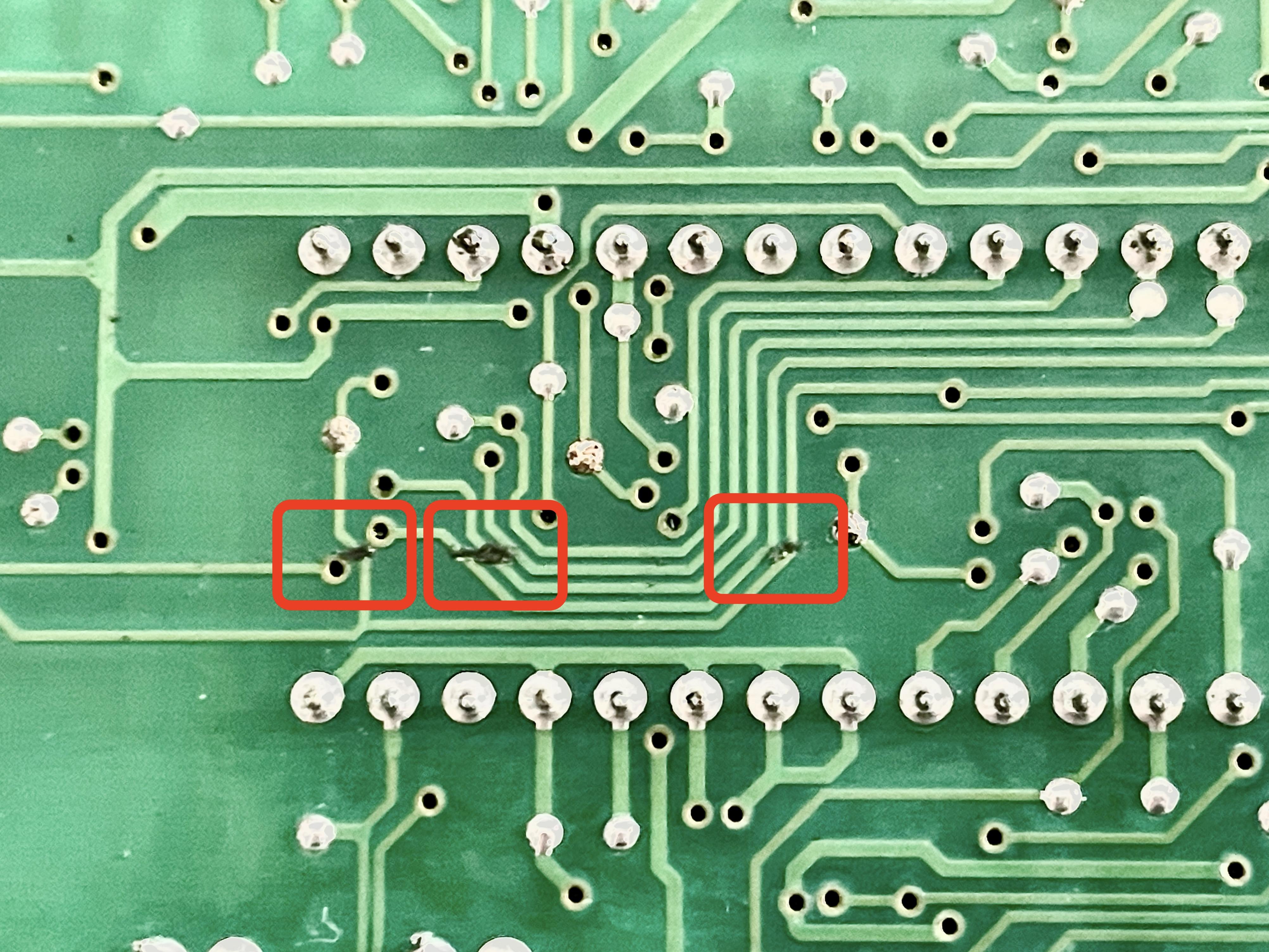
Before moving on I decided to check the IR-PCB and it’s traces more closely.
I found some foam remains sticking to and covering 2 or more traces (see 1st picture).
So I decided to clean them first, which went pretty easy. And after cleaning I placed the board back and tested it again with the remote. It did not solve my issue; the BeoLab 3500 still doesn’t not respond to the Beo4.
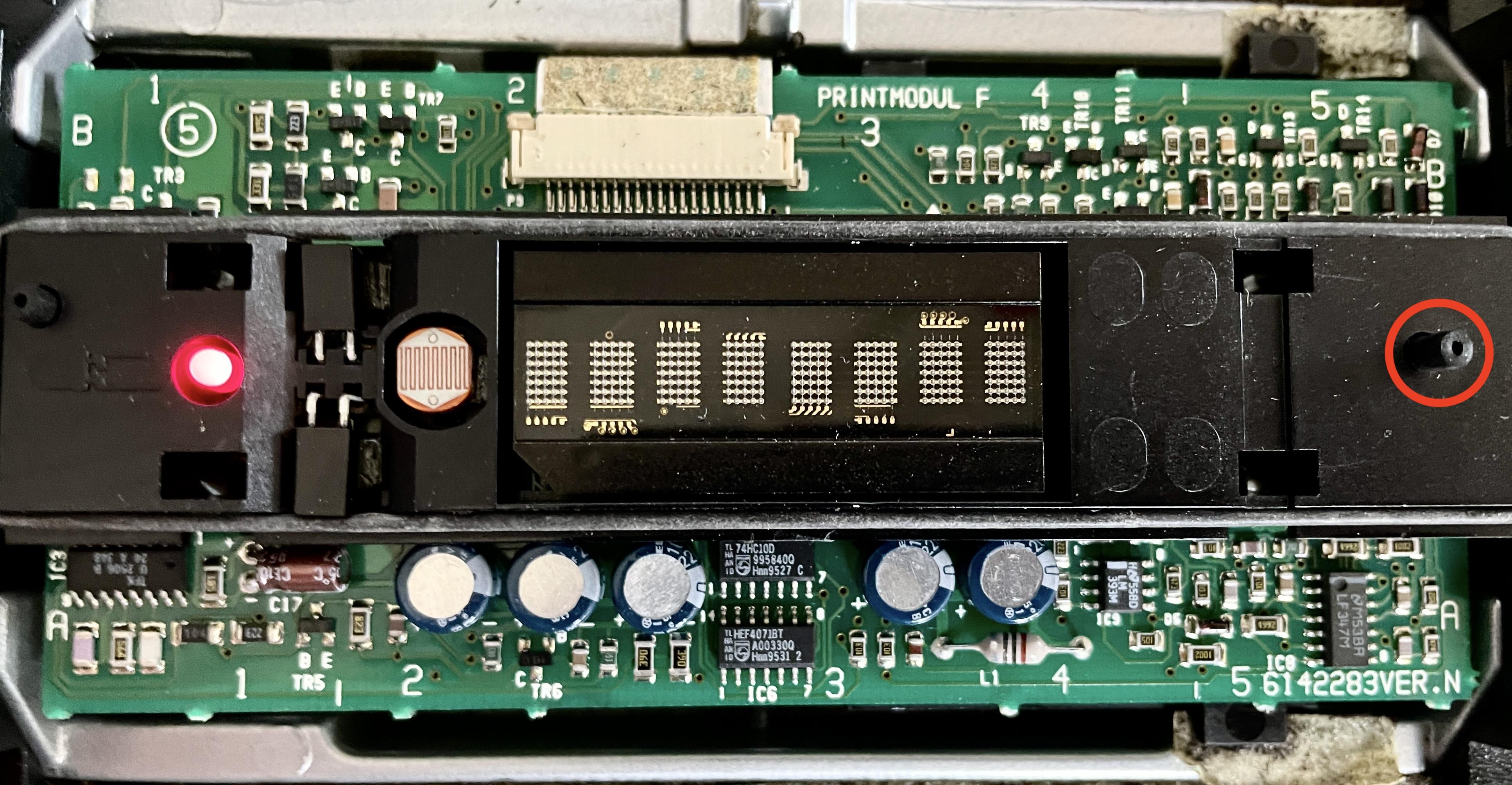
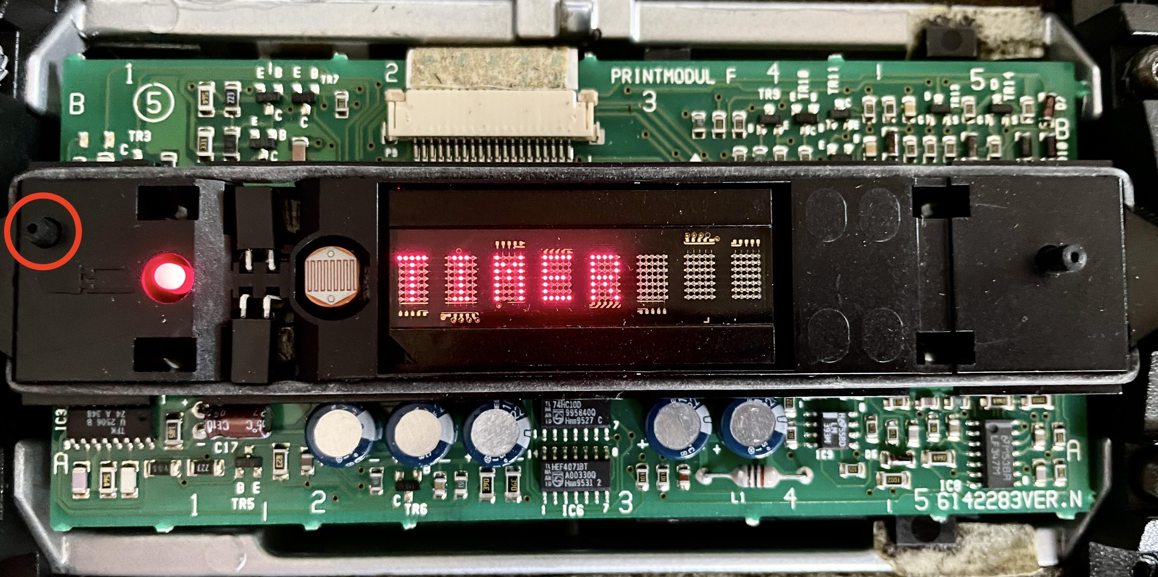
Also I would like to share what the display looks like. here’s some pictures:
(1) Display after Power On: It shows ‘:’ in the 4th segment and ‘*’ in the 8th segment.

(2) Display after pressing the Right button: all segments are blank and sometimes the red LED stains On but sometimes it goes Off.

(3) Display after pressing the Left button: the segments show ‘TIMER’.

Maybe this gives more information for additional diagnoses.
Question:
- Does this change anything for what I am about to do?
(I am about to do what B3OHACK3R advised me to do, read above)
Location: The Netherlands
Favourite Product: BeoSound 9000
My B&O Icons:
3 February 2024 at 12:35 in reply to: BeoLab 3500: sometimes responds to remote control, sometimes it doesn’t ? #52564Concerning your remark to get to the components to be replaced:
“The IR related parts are underneath the internal bracket that holds the display in place.
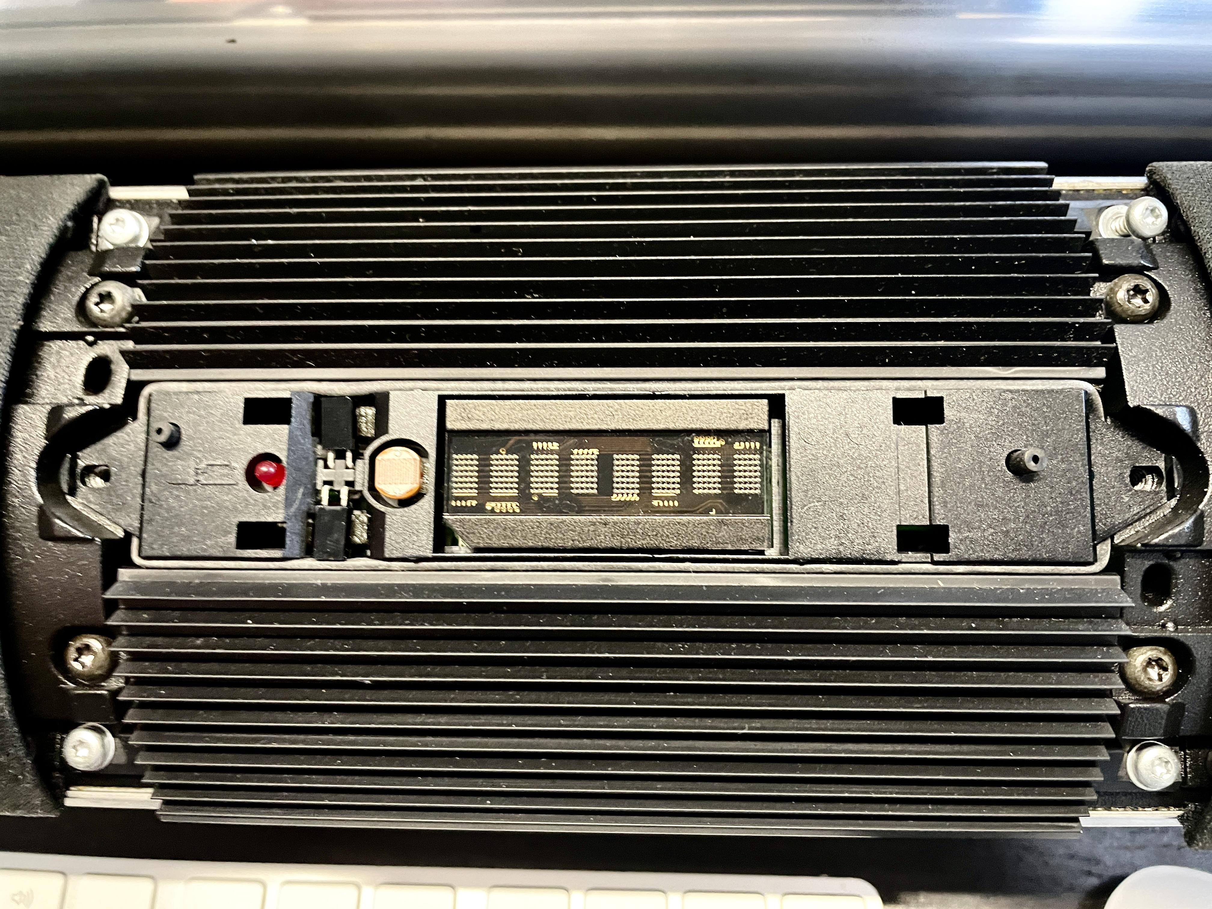
For removing that you have to carefully desolder the red LED, the photo-resistor and the two IR sensors.”I think what you mean is: (see 1st picture below)
- De-solder the 2 points in the yellow square for the photo resistor.
- De-solder the 4 points in the blue square (the legs of the two IR-sensors.
- De-solder the 2 points in the reed square for the photo resistor.
- De-clip the 4 plastic feet from the PCB and lift the plastic bracket at the front to access the components underneath. (2nd picture below)
Is this the right understanding?
Location: The Netherlands
Favourite Product: BeoSound 9000
My B&O Icons:
2 February 2024 at 15:24 in reply to: BeoLab 3500: sometimes responds to remote control, sometimes it doesn’t ? #52563Thanks for your comment Guy, nice hearing from you again!
I haven’t exactly tried what you described. Though I have tested both Beo4’s on a BeoSound Ouverture for normal operation. Both Beo4’s and the Ouverture responded well to remote control operation, each time.
Concerning the Test Mode on the BeoLab 3500, I wasn’t aware that this is a testmode command set. I just use this command to activate the DIN connector for audio input (MCL set).
But I must also add that I have been using another BeoLab 3500 (currently not in my house) this way for 2 years. It always responded well to this type of remote control operation. So my guess is that the comment by B3OHACK3R could help solve this.
Location: The Netherlands
Favourite Product: BeoSound 9000
My B&O Icons:
2 February 2024 at 11:35 in reply to: BeoLab 3500: sometimes responds to remote control, sometimes it doesn’t ? #52560Good that you mention that B3OKACK3R.
Two questions:
- Are the capacitors to be replaced electrolytic’s or SMD’s?
- Do you happen to have a picture of how that PCB looks like?
Location: The Netherlands
Favourite Product: BeoSound 9000
My B&O Icons:
1 February 2024 at 17:04 in reply to: BeoLab 3500: sometimes responds to remote control, sometimes it doesn’t ? #52558Thanks @B#OHACK3R, that’s great info!
I guess it is a matter of getting the display part out.
Is the PCB with the mentioned IR-receiver chip and capacitors, right behind that?
Location: The Netherlands
Favourite Product: BeoSound 9000
My B&O Icons:
Update > Solved
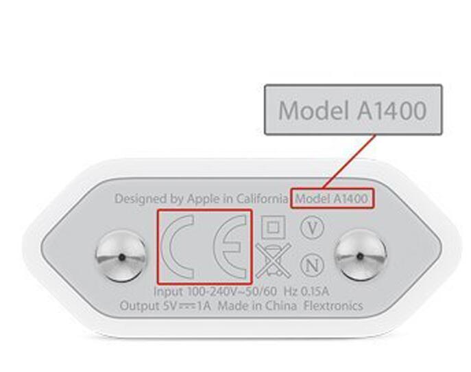
Here’s another update, after having received the Apple A1400 USB wall outlet charger.
I can now confirm it is true. This charger / step-down converter does not cause any Hum. To be exact, there is a little Hum, but only hearable when the ear is within 20cm of the speaker driver.
Important notice: there are many USB chargers that claim to be Apple Original, but are not. Since Apple sometimes changes the design, it makes sense to check the Apple website for information on checking the originality. Mine looks like this and works:

Thanks everyone for thinking with me and suggesting checks and solutions!
Location: The Netherlands
Favourite Product: BeoSound 9000
My B&O Icons:
-
AuthorPosts