Forum Replies Created
-
AuthorPosts
-
 BRONZE Member
If you don’t have/know how to handle a multimeter, try to find someone who does, and has understanding of power supplies and amplifiers.
Location: The Netherlands
Favourite Product: BeoSound 9000
My B&O Icons:

Hi mojofml,
Do you have a multimeter and know how to handle that?
Location: The Netherlands
Favourite Product: BeoSound 9000
My B&O Icons:
Very unfortunate to hear that, it is such a beautiful product.
I just ha d a look in the service manual, and noticed that the power transformers are near the PCB’s that are in the middle. Of course that are cooling elements. But I can imagine that high temperatures in such small casing, after years of use, do have impact in the electronics.
What I am saying, is that the soldering of the IR-PCB might suffer from loose connections or cracks in the soldering. If you have nothing to loose, you could try to check that, and do some reflowing of the soldering with an soldering iron, or the ‘oven trick’.
Location: The Netherlands
Favourite Product: BeoSound 9000
My B&O Icons:
Concerning your remote, so it is a BEO4?
Does the display of the BEO4 show responses when you press buttons?
Maybe stupid, but did you check the batteries?Location: The Netherlands
Favourite Product: BeoSound 9000
My B&O Icons:
Hi Jg1976.
You mention you can’t activate your BeoLab 3500 MK1 to listen to the MCL socket.
What does your display show after pressing ‘Menu > Menu > 0 > 4 > Go’ ? (This sequence should switch the BeoLab 3500 to the MCL input)
You could also check your BeoLab 3500 in ‘Test mode’. To do this press ‘Menu > 0 > 2 > Go’
And then check what you see in the display:- ML OK = Master Link Connection is OK
- NO ML = Master Link is not connected
- Error 1 = Address configuration not possible
- Error 2 = Master Link data pulled low
- Error 3 = Master Link data pulled high
- Error 4 = Data collision on Master Link
If you see ‘ML OK’, the BeoLab functions properly, and your cable will probably be wrong. Connections and pins used might be the problem.
If you are handy yourself, you can make such cable yourself. Lots of info on this forum.
You can also ask @Steve of SoundsHeavenly to help you with the right cable.Location: The Netherlands
Favourite Product: BeoSound 9000
My B&O Icons:
Thnx Guy.
Your right, I’d like to build something (small!) that handles auto-sensing and switching from stand-by to ON, automatically.
Location: The Netherlands
Favourite Product: BeoSound 9000
My B&O Icons:
Thanks for your suggestions!
I know both sources sell trigger cables. I prefer to build something myself, as I want to integrate my whole setup inside the BeoLab 2. The smaller I can get things, the better. So I prefer to have a scheme for such and build something myself.
Location: The Netherlands
Favourite Product: BeoSound 9000
My B&O Icons:
I think you guys are right, about the two versions.
I also think the 2nd version is ‘easier’ to rebuild as the values of the capacitors are closer to components available.
Location: The Netherlands
Favourite Product: BeoSound 9000
My B&O Icons:
Very interesting approach!
This is obviously the way B&O equipment handles it.
I would be very much interested in a electronics scheme, and make such to try it out.Any chance you know how such would look like?
Location: The Netherlands
Favourite Product: BeoSound 9000
My B&O Icons:
Thnx very much Guy & Carolpa!
The Playmaker, BeoSound Core or Essence are unfortunately no options for this project. I am looking at a way to integrate the streaming completely inside the speaker casing. So no PowerLink cables, only a power cable and no boxes outside the speaker casing.
So I wonder if the 5v triger is something I can create somehow inside the BeoLab 2.
Location: The Netherlands
Favourite Product: BeoSound 9000
My B&O Icons:
Thanks for responding Die Bogener!
Questions:
- So you mean to say, the only way to get a permanent DC voltage is from the stand-by transformer? Or are there any other points which I could combine with a converter to bring it to DC 5v?
- I think I have a BeoLab 8000 here with a defect standby transformer. Is there any way I can get a replacement stand-by transformer?
Location: The Netherlands
Favourite Product: BeoSound 9000
My B&O Icons:
Correction, Keith of course!
Location: The Netherlands
Favourite Product: BeoSound 9000
My B&O Icons:
That’s a great improvement Steve!
Thanks.
Location: The Netherlands
Favourite Product: BeoSound 9000
My B&O Icons:
Thnx @Mexking & @ RaMaBo !
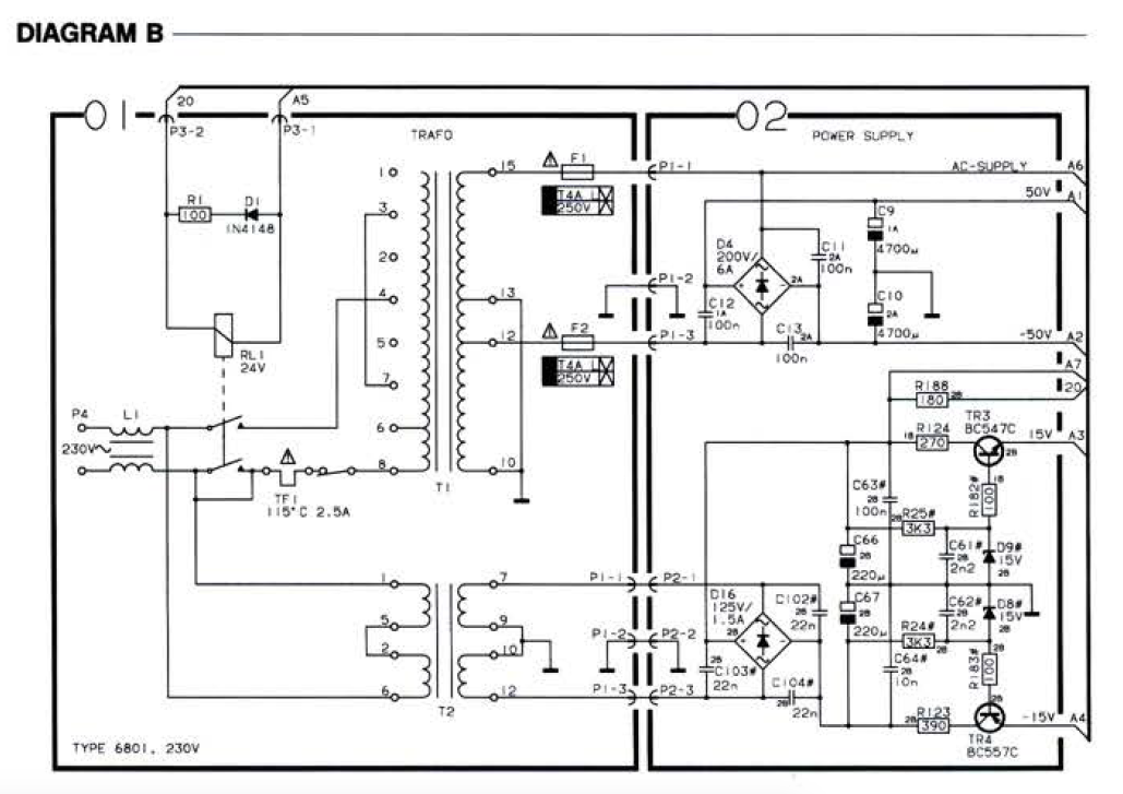
Interesting that there are some differences in the values of certain components; between the info I posted in the start of this Thread and the info in the schematics & parts list of Mexking.
E.g.
- Capacitor #22 and 23 = 200uF/25v vs. 80uF/25v
- Capacitor #49 and 51 = 80uF/25v vs 1.6uF/25v
Is this correct?
Location: The Netherlands
Favourite Product: BeoSound 9000
My B&O Icons:
I am also looking for a permanent DC voltage on the BeoLab 8000. Can you help me confirm that?
Is it 15v DC after capacitor C66?

Location: The Netherlands
Favourite Product: BeoSound 9000
My B&O Icons:
Component search
I have done a quick check for components. There’s two challenges that I see:
- Some components have values that are not very common any more, e.g.: capacitor 10uF/6.4v, 80uF/25v, 100uF/6.4v, etc.
- I have to make sure that the sizes of the components chosen are the same, to make it fit on the original board remake.
Questions(a) Can anyone recommend an online source where components with these ‘vintage’ values can be found?
(b) Are the diode types AO70 & AO81 interchangeable? Or does it depend on the version of the board which one to choose?Location: The Netherlands
Favourite Product: BeoSound 9000
My B&O Icons:
Thnx for hooking in Mexking.
Where do you see ‘OA81’?
In the picture of the board, I can see something is printed in red on the component. But I can’t read it.
The B&O schematics says ‘OA70’. So I assume that is correct.
Location: The Netherlands
Favourite Product: BeoSound 9000
My B&O Icons:
I only have a picture, so I can’t look around the component.
But I believe you are totally right Martin. Your explanation makes perfectly sense!
Thanks again. I am getting closer to have all information for replicating the original!
Location: The Netherlands
Favourite Product: BeoSound 9000
My B&O Icons:
#22 & #34:

#31:

Location: The Netherlands
Favourite Product: BeoSound 9000
My B&O Icons:
Thnx a lot Martin, clear!
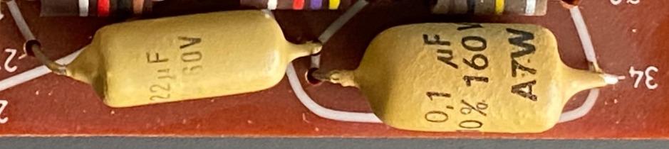
At the bottom right on the PCB, there’s two light brown capacitors: #27 & #34. And on the other side there also two: #31 & #32.
The schematics says:
- #27 = 22n
- #31 = 22n
- #32 = 0,1u
- #34 = 0,1u
The picture of the components says:
- #27 = 22uF, 160v
- #31 = 22uF, ?v
- #32 = ??, ?v
- #34 = 0,1uF, 160v
Questions:
- I guess the picture is right and the schematics to be ignored on this point?
- Are these ‘Orange Drop’ Capacitors?
- Are they all 160v, and this it matter of the voltage of the replacement differs?
- I guess #32 is also 0,1uF?
Location: The Netherlands
Favourite Product: BeoSound 9000
My B&O Icons:
-
AuthorPosts