Forum Replies Created
-
AuthorPosts
-
 DillenModerator
Nice video.
Wrongly adjusted tracking opto (diaphragm).
Could also be that the tonearm alignment is way off, but that’ll usually be visible, and yours doesn’t look that wrong.Martin
3 November 2023 at 07:33 in reply to: Beomaster 1900 – No sound in left channel on phono/tape input #50038DillenModeratorWas this problem also present before you started work on the Beomaster?
Martin
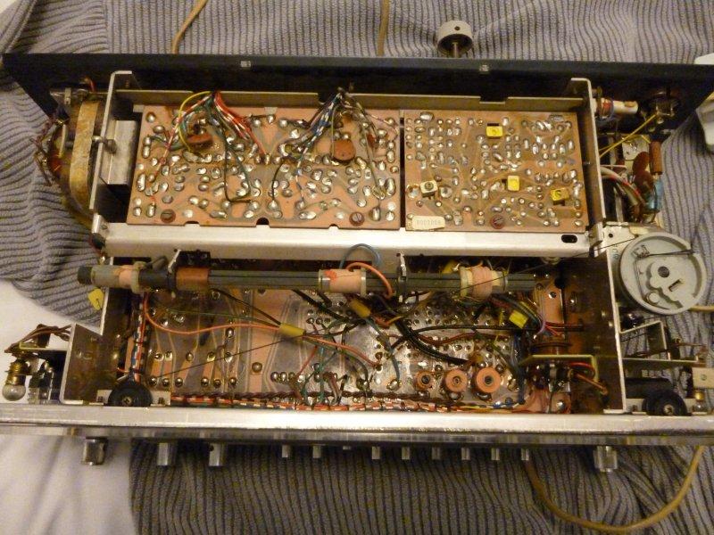
DillenModeratorThe decoder is the module to the right of the amplifier module in this photo.
It has no visible leads out side this.
When Tape or Phono is selected as source, the stereo light should be lit.
If it flashes, it could be because of a bad switch contact or the lamp is not securely fixed in
its socket. Or the lamp itself is on its way out.Martin
(Photo from http://www.vintage-radio.net)DillenModeratorThe stereo decoder module was an optional extra in Beomaster 900K.
Not all Beomasters had them installed.
If no stereo decoder module has been installed, FM reception will be mono only, and the stereo indicator won’t light up.Martin
DillenModeratorAnd some versions have protective diodes at the datalink signals. They can short.
Martin
DillenModeratorThis?
Knock out the small steel pin that goes through the gear, then the hub with spindle etc. can be lifted up.
Martin
DillenModeratorNew datalink pins here:
Beoparts-shopMartin
DillenModeratorNo!
A good rule of thumb is to start with a trimmer in its center position, as that
usually won’t be far from its correct setting (if everything else in the circuit is fine).Besides, the amplifier PCB in Beomaster 3000 (-2) has left and right channels mirrored,
so fully clockwise would mean max idle for one channel. Not good!Martin
30 October 2023 at 08:38 in reply to: Refoaming Pentas. speakerrepairshop or repairyourspeakers #49921DillenModeratorThe original gaskets can become immensely brittle.
In these cases it’s nice to have the possibility to simply replace them.Martin
DillenModeratorOh, I agree that looks horrible. It would be difficult to restore back.
Beocenter 4600 and Beocenter 7002 use different tonearms. The one in your photo could be
from a Beocenter 4600.
Which one do you need, – I could look in the dungeons for the right part.Martin
DillenModeratorThat’s not antiskating. It’s the tracking force setting.
It’s something you would normally not take apart. Originally, it was sold only as a complete assembly and, unless you are a really skilled DIY’er, I would recommend you replace it as such.Martin
DillenModeratorAnd use ESD-protection!
These things are highly sensitive to static electricity.
Many owners experience that new lasers don’t work, – and while it is correct that
many asian “counterfeits” won’t work, or only work for a few hours, many lasers
are damaged by static electricity, – either during shipping, if shipped without
shorting clamp and/or ESD-shielding or by handling without taking
proper ESD-precautions.
I have seen many of both cases.Martin
DillenModeratorThere can be many reasons.
A photo or two would help us diagnose the issue.Martin
DillenModeratorThe belt will not be the problem then.
I suggest you add a small drop of oil to the motor bearing. Usually, the outer (visible) bearing will dry out before the inner, and it’s also the outer bearing that takes most
of the sideways load, so I would start there.
A little sinter/spindle oil would be the choice.Martin
DillenModeratorWhat “special lubricant” did you use?
Martin
DillenModeratorYou can be sure to find the correct part here:
https://www.beoparts-shop.com/product-category/beogram/beogram-rx2/Martin
DillenModeratorIt can be the idler wheel. A short production run of wheels was completed, and some
were already sold, before it was discovered, that the rubber compound wasn’t quite
as homogenic as it should have been from the raw material supplier.
Production was of course halted, and most buyers who potentially could have been affected, were contacted directly.
Luckily, the majority reported no problems but a few had issues as you describe.
I cannot say if the wheel you sit with is one from this batch, – but it could be.
If the wheel is indeed the problem, I suggest you contact the shop. They will have a solution.Martin
DillenModeratorIs the tape under a hinged lid on top or in a drawer coming out the front?
Martin
28 September 2023 at 06:58 in reply to: Beolab Penta MK3 amplifier LED stays orange in standby #49360DillenModeratorDoes it click on and off and play as it should?
Martin
DillenModeratorSince this is a single-supply amplifier, apprx 50% of VCC is to be expected on the output rail – with respect to ground.
(Hence the need for an output series capacitor).Martin
-
AuthorPosts