


Home › Forums › Product Discussion & Questions › BeoLab › BeoLink Converter 1611 Innovative Configurations
- This topic has 507 replies, 21 voices, and was last updated 2 months, 3 weeks ago by
 Madskp.
-
AuthorPosts
-
18 January 2023 at 11:30 #42395
 MadskpGOLD Member
But I’ve also read many times on the forum that the Powerlink socket on the 3500 is there for use with W1. I suppose they were different version of W1 over time, one of which uses Powerlink and the other Masterlink, right? But even then, Why would the Beolab react to a Powerlink connection from W1 only and not any other device?
It is mentioned i the specification list in the servicemanual for The BL3500 MK2, and I also have seen manuals for the wireless 1 with drawings where it has Two powerlinks sockets and one Ir socket, and in a user manual for Beolab 3500 it only has one DIN socket and is connected via ML. So guess there must have been at least two versions of the W1
Location: Denmark
18 January 2023 at 11:37 #42396Out of curiosity: Did you try the combination +5V on pin 6 (datalink) and -5V on pin 7 (datalink shield)? I have had some thought about this and cam to the conclusion that the rest of the pins are either not conencted or used for the sound part. Furthermore one of the olde manuals regarding datalink signals mentions high signals in the voltage range 2.1 to 5.5V. But again it is just a thought.
Great minds think alike! I came to the same conclusion about pin 6 and did try 5v to that with pin 7 as ground (not -5V). I was actually using 4.5V (3 x 1.5v cells). Mine is SW2.0 whereas Matador’s picture from the one that worked says SW1.1 – perhaps that’s the problem?
Location: Warwickshire, UK
My B&O Icons:
 18 January 2023 at 11:45 #42397MadskpGOLD Member
It is mentioned i the specification list in the servicemanual for The BL3500 MK2, and I also have seen manuals for the wireless 1 with drawings where it has Two powerlinks sockets and one Ir socket, and in a user manual for Beolab 3500 it only has one DIN socket and is connected via ML. So guess there must have been at least two versions of the W1
Or maybe the BL3500 manual is not showing all the connectors on the W1
Location: Denmark
18 January 2023 at 11:47 #42398Or maybe the BL3500 manual is not showing all the connectors on the W1
I am fairly sure that I have a broken Wireless 1 in one of my boxes, but can’t find it unfortunately – which is a shame because I could have looked inside!
Location: Warwickshire, UK
My B&O Icons:
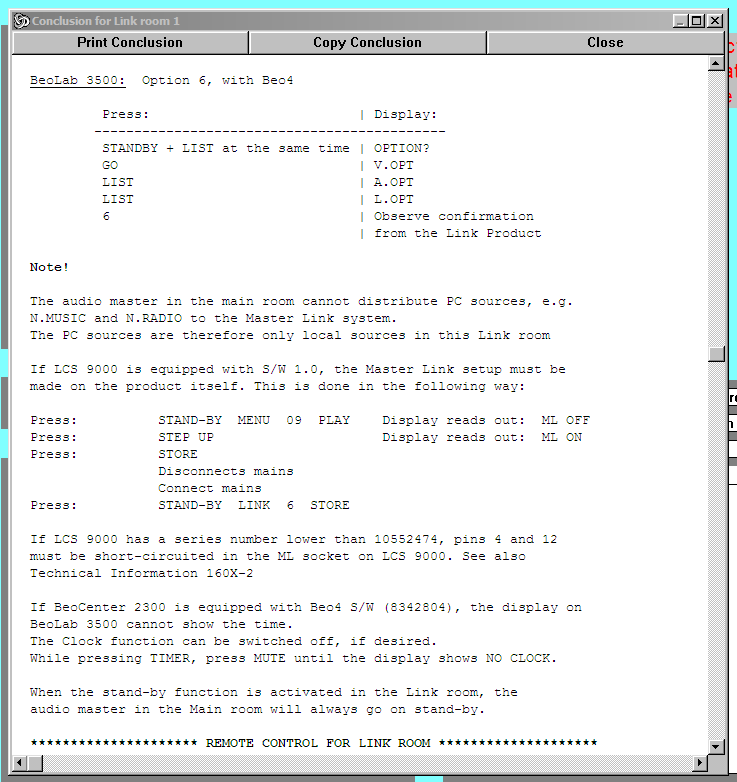
18 January 2023 at 12:06 #42399I am not sure if it’s relevant, but if I run the PCG with a BC2300 and BL1611 in the main room and LCS9000 in the link room (connected by ML) then I get the following:

Perhaps the shorting (or otherwise) of ML pins 4 and 12 in early model BL3500s is relevant to our investigations?
Location: Warwickshire, UK
My B&O Icons:
18 January 2023 at 12:08 #42400MadskpGOLD MemberOr maybe the BL3500 manual is not showing all the connectors on the W1
Ok, so I confused my self, and probably also you. I misunderstood the drawing in the Beolab 3500 manual thinking it was showing the connections on the Wireless 1, but it is of course the connections on the BL3500. Sorry for that.

Location: Denmark
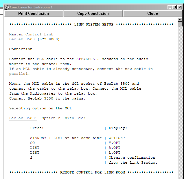
18 January 2023 at 12:14 #42401A setup with BC9500 in the main room and connected by MCL to LCS9000 in link room has no complications, as follows: (I presume that a relay box is just a connection box?)

Note that the above states Option 2 rather than L.OPT 6. I did try L.OPT 2 on my BL3500 when I was trying to trigger with 5V.
Location: Warwickshire, UK
My B&O Icons:
18 January 2023 at 12:19 #42402Perhaps the shorting (or otherwise) of ML pins 4 and 12 in early model BL3500s is relevant to our investigations?
Beolink Handbook shows Masterlink and Obsolete Masterlink wiring,
pin 12 is “+ supply voltage” in both case, pin 4 is not connected in Masterlink and “+ supply voltage” too in obsolete Masterlink.Shorting Pin 4 and 12 would therefore mean “the device expect positive voltage on pin 4 but because we have changed our wiring, you have to take it on pin 12”. Right?
Location: Paris France
18 January 2023 at 12:29 #42403MadskpGOLD MemberPerhaps the shorting (or otherwise) of ML pins 4 and 12 in early model BL3500s is relevant to our investigations?
It doesn’t say why they have to be shorted, and weird since pin 4 is normally not connected in masterlink.
What I can’t make of it is in most normal B&O link use cases the activation of the speaker will be from the speaker it self (or via IR). So the turn on feature might be a non standard thing
Location: Denmark
18 January 2023 at 13:40 #42404MadskpGOLD Membersounds more or less as the experience I had with the BV6, 1611 and Beocord 3500. Didnt try the long press off though. Will test that for my next testing session
I came around to try this test, but the Beocord keept playing even though i tried various lengths of long presses.
Might be the difference between AAL an AL.
Location: Denmark
18 January 2023 at 14:42 #42405I came around to try this test, but the Beocord keept playing even though i tried various lengths of long presses. Might be the difference between AAL an AL.
That makes perfect sense. It also explains …
- … why my modified DVD1 turned off after a long press. DVD1 had full control when connected to AUX/TV socket of BC9500, because the BC9500’s AUX/TV socket must have AAL at Pin 6. Given that I used a modified SCART lead, the data within SCART must be AAL rather than Datalink.
- … why my OneRemote has to be programmed to a strange number (starting with 4XX) when connected to either BL1611 or a TV’s SCART socket. This makes it use AAL rather than Datalink.
Location: Warwickshire, UK
My B&O Icons:
18 January 2023 at 14:45 #42406MadskpGOLD MemberBeolink Handbook shows Masterlink and Obsolete Masterlink wiring, pin 12 is “+ supply voltage” in both case, pin 4 is not connected in Masterlink and “+ supply voltage” too in obsolete Masterlink. Shorting Pin 4 and 12 would therefore mean “the device expect positive voltage on pin 4 but because we have changed our wiring, you have to take it on pin 12”. Right?
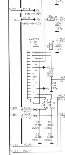
I took a look at the diagrams in the servicemanual for LCS9000/Bl3500MK1, and it actually shows pin 4 being connected to whats called V ml instead of pin 12, so this explains the text from the product configurator. Why it is made this way I cant see a logical reason for

Location: Denmark
18 January 2023 at 14:48 #42407MadskpGOLD MemberThat makes perfect sense. It also explains … … why my modified DVD1 turned off after a long press. DVD1 had full control when connected to AUX/TV socket of BC9500, because the BC9500’s AUX/TV socket must have AAL at Pin 6. Given that I used a modified SCART lead, the data within SCART must be AAL rather than Datalink. … why my OneRemote has to be programmed to a strange number (starting with 4XX) when connected to either BL1611 or a TV’s SCART socket. This makes it use AAL rather than Datalink.
Great. Then we at least seem to have figured out what will work and what will not for that part.
Location: Denmark
18 January 2023 at 14:49 #42408I came around to try this test, but the Beocord keept playing even though i tried various lengths of long presses.
Forgot to ask, did you connect the BeoCord’s datalink to the AAL pin 6, rather than the usual Beocord pin 7?
Location: Warwickshire, UK
My B&O Icons:
18 January 2023 at 14:57 #42409MadskpGOLD MemberI came around to try this test, but the Beocord keept playing even though i tried various lengths of long presses.
Forgot to ask, did you connect the BeoCord’s datalink to the AAL pin 6, rather than the usual Beocord pin 7?
yes, i have made an adapter to reverse pin 3, 5 and 7 to 1, 4 and 6
Location: Denmark
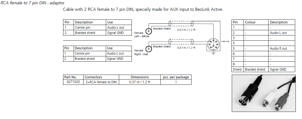
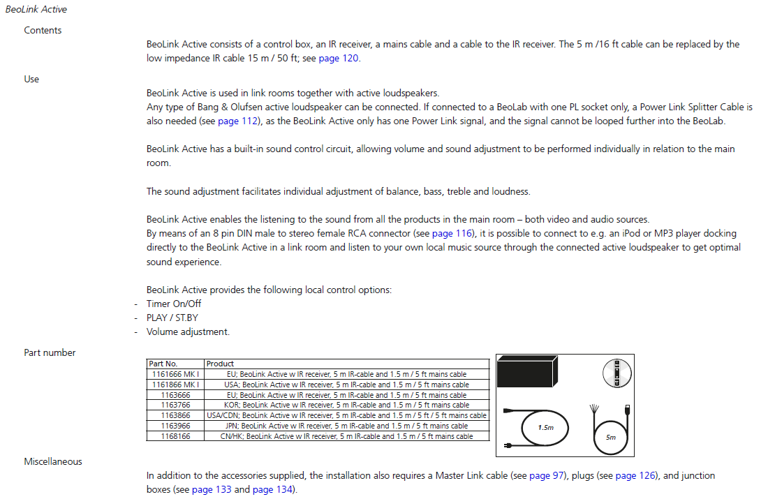
19 January 2023 at 02:10 #42411MadskpGOLD Member. I also made up a lead to test the PC input of the BL Active, only because I had never tried that before. The PC input worked fine using pins 2, 4, and 7 for Left, Right and Gnd respectively. I could select using ‘PC’ on Beo4 and it worked as a local source, but as soon as I disconnected the ML it stopped working – so there is no simple BL Active standalone option.
not knowing much about the Beolink active I am s little confused about thisPC connection. It is not mentioned in the user-, reference or servicemanual availeble on Beoworld, and this older thread https://archivedforum.beoworld.org/forums/p/15997/128504.aspx mentions it but with other pin numbers.
has there been different versions of this product?
Location: Denmark
19 January 2023 at 13:31 #42410Final (?) version of Test Schedule attached.
I entered a few final notes (in blue) about my attempts to trigger BL3500 using 5v into the MCL socket. I also made up a lead to test the PC input of the BL Active, only because I had never tried that before. The PC input worked fine using pins 2, 4, and 7 for Left, Right and Gnd respectively. I could select using ‘PC’ on Beo4 and it worked as a local source, but as soon as I disconnected the ML it stopped working – so there is no simple BL Active standalone option.
I have finished testing setups for now, but am now on the lookout for a BL3500 PCB36 with SW 2.1 or later.
Attachments:
You must be logged in to view attached files.Location: Warwickshire, UK
My B&O Icons:
19 January 2023 at 14:35 #42412has there been different versions of this product?
Type 1616 (and 1618 for USA) is the first version with 2 x PL output sockets – that is the service manual that is in the Service Manual database.
Type 1636 is the later model with one of the PL sockets replaced with a PC input socket. I think that this version was introduced as the Beoport was phased out, hence the naming of the input. The input pins are definitely 4, 2 and 7 – I have it playing at the moment.
The connections are mentioned in the Beolink handbook on page 116: (although it states to use the shield as ground – I used pin 7 as shown in some of Peter Pan’s diagrams)

EDIT: Here is the product page from the same handbook, although it doesn’t mention the Mk1 v Mk2 differences.

Location: Warwickshire, UK
My B&O Icons:
19 January 2023 at 14:39 #42413MadskpGOLD MemberI entered a few final notes (in blue) about my attempts to trigger BL3500 using 5v into the MCL socket
One more thought regarding this test. In this thread https://forum.beoworld.org/forums/topic/beolab-3500-how-to-fix-ml-input-selection/#post-13452 where Matador got the info about the trigger Pin assignments it was pin 1 and 7.
This would make little sense for powerlink where Pin 1 is power up and pin 7 is data ground.
But for the MCL connctor that it must be for the confirmed working unit with the low serial number and old software version it makes not as much sense as pin 1 is signal left and pin 7 is data shield (ground).
What if this Curios Dreamer misinterperted the pin numbers and had reversed them? Then it Would be pin 3 Ground left channel and pin 6 Datalink which would make more sense in my head. Note that Pin 3 ground is not directly connected to ground but through a resistor and a capacitor, so not quite the same as pin 7.
Don’t know if you already tried that combination Guy or are willing to try it, but here is the idea
Location: Denmark
19 January 2023 at 14:42 #42414MadskpGOLD Memberhas there been different versions of this product?
Type 1616 (and 1618 for USA) is the first version with 2 x PL output sockets – that is the service manual that is in the Service Manual database. Type 1636 is the later model with one of the PL sockets replaced with a PC input socket. I think that this version was introduced as the Beoport was phased out, hence the naming of the input. The input pins are definitely 4, 2 and 7 – I have it playing at the moment. The connections are mentioned in the Beolink handbook on page 116: (although it states to use the shield as ground – I used pin 7 as shown in some of Peter Pan’s diagrams)
Ok that makes sense. Odd that the pin configuration on this input has to be special, but maybe a way for B&O to reuse the PCB’s in the box without to much changes
Location: Denmark
-
AuthorPosts


- You must be logged in to reply to this topic.