Forum Replies Created
-
AuthorPosts
-
 TKBRONZE Member
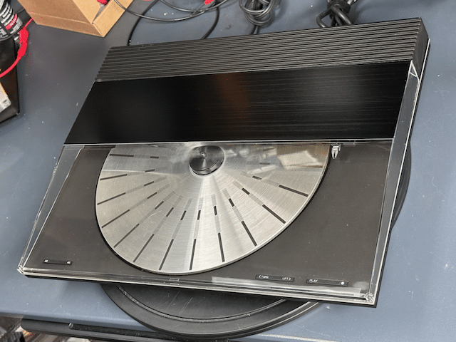
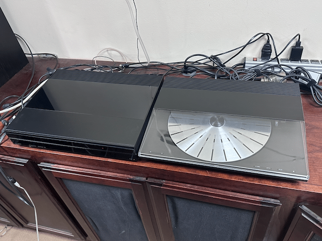
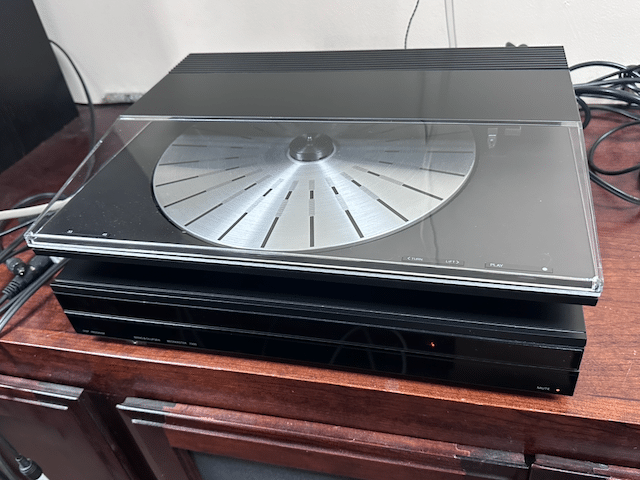
I have a black Beosystem 7000 which lacked a turntable, and instead of spending $1000+ to find a matching Beogram 7000, I set about retrofitting a old BG 3000 to match the look, using available parts I could buy online.
 The original 3000 lid was cracked, so I opted for a clear replacement from DK Sound Parts, along with a black metal decorative top plate. In the end, IMHO it’s an ‘ok’ match with the BM7000, but not perfect – I give it a 7/10. Perhaps if I had selected the dark grey lid option, it would bland a bit better, especially since the platter is not black.
Here are my costs, including delivery:Beogram 3000 – $75RIAA card – $1254500 lid – $120Top Plate – $20Misc parts – $40———————-Total: $380I think I got a bit fortunate on the purchase price of the BG 3000, so I’d venture to say that a more typical budget would be in the $450-500 range. In the end, I’m pleased with the results, although I’m not sure I’m really saving all that much in comparison to buying a good-condition stock 4500. All that being said, I’m a bit of a purist, so if a black Beogram 7000 comes up for less than $1000 delivered, I’ll probably still look to acquire it.TKBRONZE Member
The original 3000 lid was cracked, so I opted for a clear replacement from DK Sound Parts, along with a black metal decorative top plate. In the end, IMHO it’s an ‘ok’ match with the BM7000, but not perfect – I give it a 7/10. Perhaps if I had selected the dark grey lid option, it would bland a bit better, especially since the platter is not black.
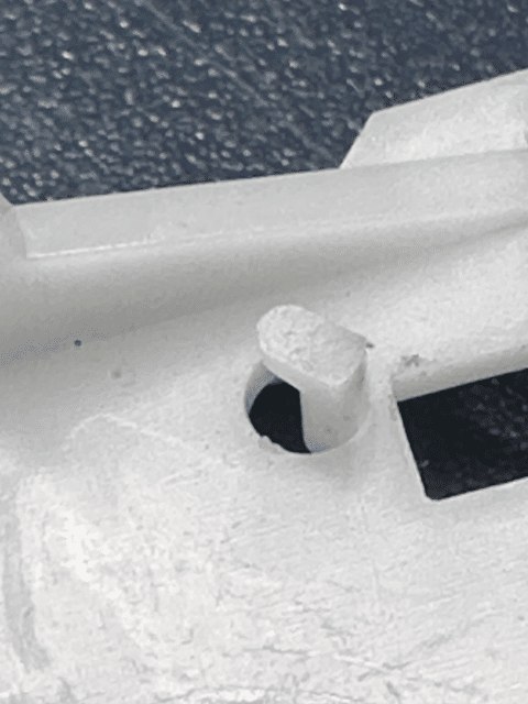
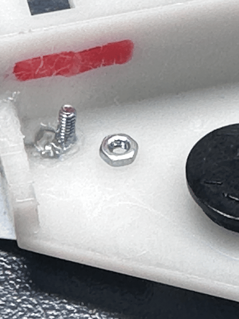
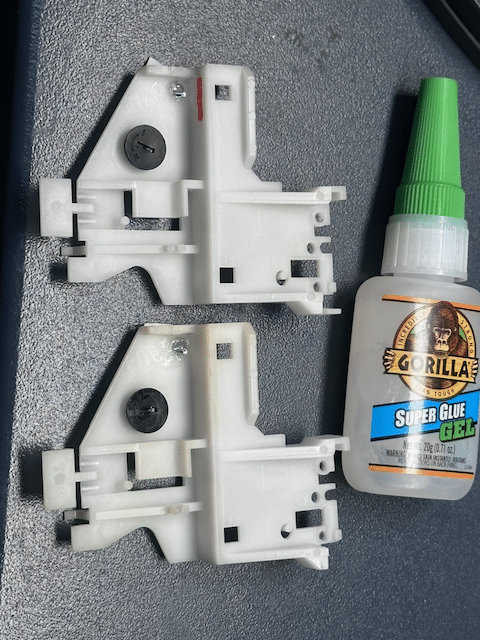
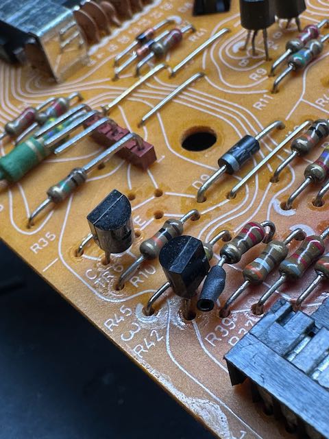
Here are my costs, including delivery:Beogram 3000 – $75RIAA card – $1254500 lid – $120Top Plate – $20Misc parts – $40———————-Total: $380I think I got a bit fortunate on the purchase price of the BG 3000, so I’d venture to say that a more typical budget would be in the $450-500 range. In the end, I’m pleased with the results, although I’m not sure I’m really saving all that much in comparison to buying a good-condition stock 4500. All that being said, I’m a bit of a purist, so if a black Beogram 7000 comes up for less than $1000 delivered, I’ll probably still look to acquire it.TKBRONZE MemberHere’s a solution that no one really was asking a question about. The tiny tab that holds the thread ends which move the tone arm sled tends to snap when things bind up. This morning I took a stab at a remedy.
For starters, the bottom of the sled appears to contain an extra tab that does not appear to be used for anything, so my first thought was to carefully slice this off and find a way to graft it in place of the missing one.
I decided to forego that option, and opted instead to head to the hardware store to purchase a few 1.6mm bolts with nuts. This would provide a bit more holding surface and friction. The idea is to place the string and spring in place, and thread the nut onto the rod as a “keeper”, which would prevent the string from falling off. This new plan of action involved generously epoxying over the holes, and drilling a pilot hole I could thread with the bolt, which I thought would be stiff enough to provide a robust holding point to the thread. Alas, laziness prevailed- I went with super glue, and simply positioned the bolts during the curing phase.
We’ll see if this provides enough durability to create a lasting solution to the problem.TKBRONZE MemberPlatters also come up for sale quite frequently in various marketplaces, ranging from USD $50 to $100. In the mean time, you might consider milling two solid discs with a diameter of 10cm each. Place a layer of rubber on the bottom one for a bit of grip. Place the bottom disc on the spindle with the rubber facing up, next the record, last the top disc as a weight to hold the record in place and level to the bottom disc surface. You might need to make the top disc a bit heavier to provide additional stability. I haven’t tried this myself, but I feel like it would work fine, provided it is balanced properly, and can compensate for the 1.5g of downward pressure provided by the tone arm.
8 June 2026 at 23:59 in reply to: First look – CMM-10 type 5103: a 10-disc CD changer from 1990 #123962TKBRONZE MemberI’ve got a Sony CDX-A55 inbound that I bought for $30 off eBay which has the same pinout at the A20 – a slightly newer configuration to the original setup. I’d like to definitively know how easy it would be to add a 10-disc CD changer to an 80’s – 90’s Beosystem. Controllers tend to run $60 or so on eBay, so for under $120, you can add a 10-disc changer to your pizza box system for parties.
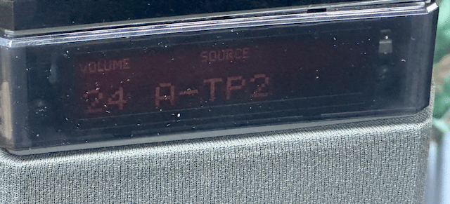
Clearly it would not have the panache of a 9000, but it would retain most of the function. On that note, I can report that the system works just fine on a Beomaster 5500 Tape or Tape 2 input with fully functional control via a Beo4 or MCP 5500, as I had expected. I have not attempted it yet, but I’d expect it to work with a 5000/MCP5000 as well, as the Datalink ’80 commands required to make it respond should be identical.
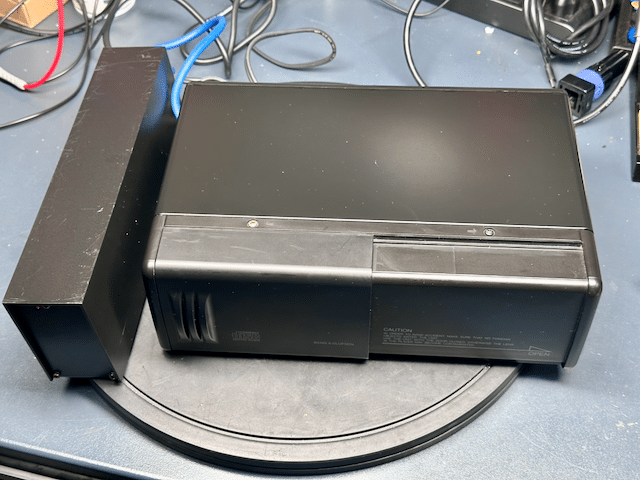
The Sony packaging is basically a metal endo-skeleton surrounded by a molded-plastic shell, with large rubber suspension bushings to deal with rough roads – something unnecessary when installed in the home. Unfortunate that B&O didn’t really bother to repackage everything in something a bit more B&O-ish. There’s absolutely no reason why the system & controller together could not fit in a form factor similar to the pizza boxes (it would admittedly need to be slightly taller) with a metal sliding door to cover the carousel – even the eject button in the usual left corner location would be compatible, and require nothing more than a wire extension to function.
Add a switch to choose between Aux and Tape 2 communication – a trivial addition for a competent programmer, and the system would have been quite versatile. Shoulda coulda woulda.
TKBRONZE Member… yet.
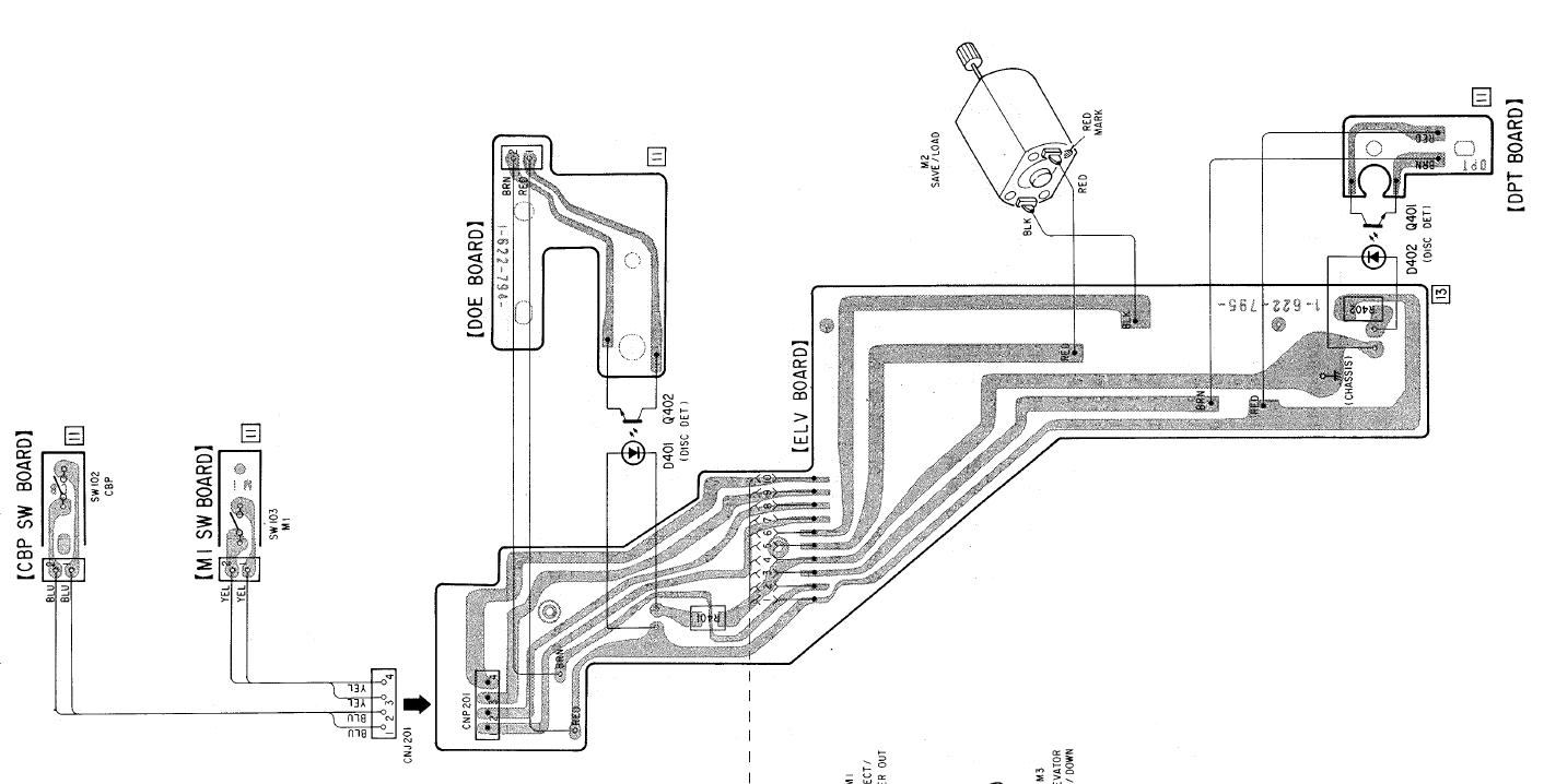
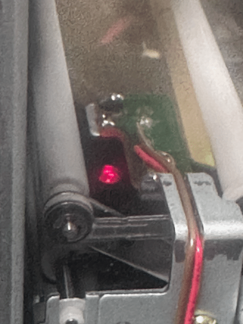
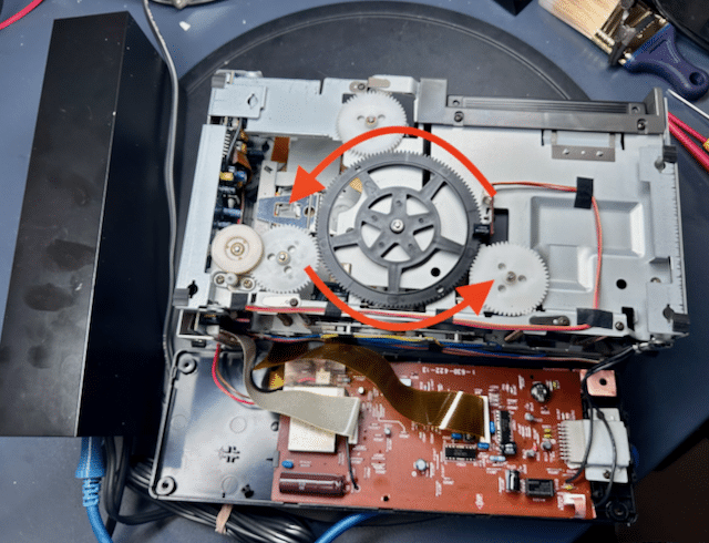
4 June 2026 at 05:31 in reply to: First look – CMM-10 type 5103: a 10-disc CD changer from 1990 #123912TKBRONZE MemberI’ve spent the last few days pulling my hair out trying to figure out all of the mechanical switches and levers on this thing. After several “one step forward, two steps back” moments (I had to disassemble the carousel twice because the elevator kept trying to shove CDs into already occupied spots) I finally got to the point where it could reliably once again cycle through a tray of CDs – loading and unloading, but failing to play anything – even failing to play with my prior hack of “upright position”. So with nothing playing, I was consigned to spending a few hours looking at ribbon cables, cleaning any mechanical switch I could find, and scouring the Sony service manual for clues as to why it wont accept a CD as “Loaded”. I finally zeroed in on this board, which handles the elevator mechanism.
Perhaps a bad seating or broken trace was the issue. Among other things, the board has 2 photo sensors – one to determine if a CD is in the player, and one to determine whether the CD is fully seated in the player tray.
I concluded that one or the other of these sensors was likely intermittent, causing the controller to determine that there was a CD jammed in the system. The readings for the “CD inserted” was indeed reading a medium short. And yet, it appeared to always be working for a specific dark-gold-colored CD, no matter where it was placed in the carousel. Odd!
… and then it hit me. These photosensors are designed to operate in total blackness. And here I was – for days – trying to poke and prod and shine my 3000 lumen desk light inside the internals to try and discern why the darn thing was not working, all the while causing the “CD Inserted” photoreceptor to constantly report a CD jam.
Ugh – I’m an idiot! I switched off my desk light, and everything began to function properly. For now – I have a hunch there are still a few gremlins left to be discovered. And they don’t like bright lights either.
-
This reply was modified 1 month, 2 weeks ago by
 TK.
TK.
2 June 2026 at 01:17 in reply to: First look – CMM-10 type 5103: a 10-disc CD changer from 1990 #123811TKBRONZE Member@madskp, I have not investigated whether the two datalink channels have slightly different implementations – my guess would have initially been that the code and routines are identical, but perhaps there was not room for everything on the ROM, and DL2 was sacrificed.
For kicks, I hooked up the CMM-10 to the ‘Tape’ input, and it works just fine as I expected. Unfortunately, I still don’t see any status updates on Datalink, so DL1 and DL2 are both not providing updates. I did a quick check to verify that the carousel was broadcasting data – and it was sending a status update once every second that a CD was actually playing – so it appears it’s more likely a case of B&O electing not to spend the extra few days to write the firmware to make player status visible. I have not spent the time to decode the Sony messages, so I’m not completely sure what is being broadcast.
I have to admit, after using the system for a while, it’s kind-of a nice-to-have product. Perhaps I can motivate myself to bump up a tighter integration implementation.
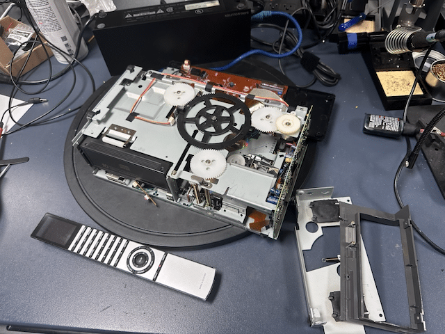
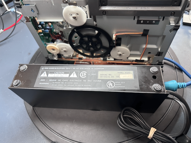
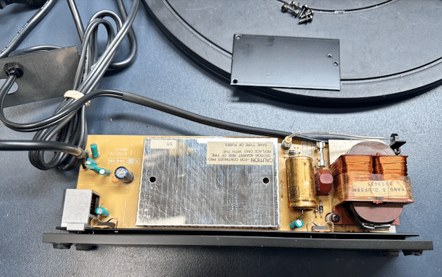
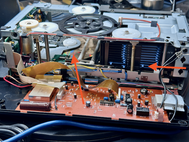
1 June 2026 at 18:18 in reply to: First look – CMM-10 type 5103: a 10-disc CD changer from 1990 #123809TKBRONZE MemberHere’s a cursory look at the 5103 internals.
It’s a fairly straightforward design, with a plastic light “Power” rod that I managed to snap the end off by not noticing it as I was disassembling the panel. Much of the logic is buried behind shielding, with a smattering of capacitors, including one huge 2200uF capacitor. For those individuals in 240V communities, the transformer does appear to be a dual-voltage transformer, part #8013435, which would make a voltage conversion simple. It also appears to share the same mounting points as several Beogram transformers I’ve been working on as of late, so a simple switch to an already-wired one would also be a possible solution. The transformer supplies +25V though a rectifier to two IC regulators, one producing 5v for internal logic, and the other producing 12V for the CD carousel.
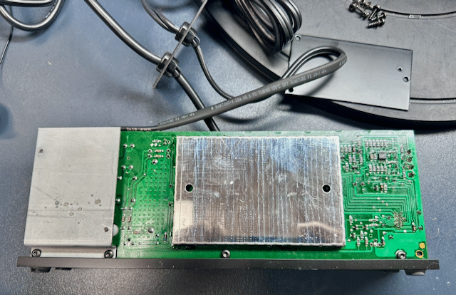
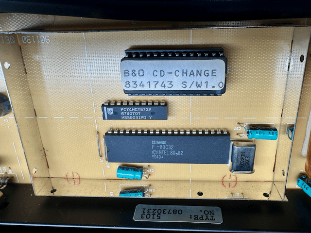
Although there are shields on both sides of the board, the chipset is only on one side, with the shield on the other side covering the pin outs. Hiding inside the shield is a ROM chip encoded as 8341743 S/W1.0 and an MHS microcontroller – basically, the 1980’s version of an Arduino!
All-in-all, it looks like a straightforward solution from B&O to quickly address an apparent hole in the product lineup, and also reasonably well made. The capacitors all tested quite excellent, so if there’s an issue with corrupted status messages, it’s not a simple capacitor swap that will right the ship. If I had more time and patience (and interest, frankly), I’d look into updating the ROM with more capabilities. The easier solution will instead be to intercept status signals coming from the carousel, and interject proper status messages onto the Datalink bus, which the Beomaster will happily interpret as being valid. This would also be the spot to activate pin 6 with Datalink ’86, and code for DL ’86 interoperability. All doable, but admittedly well down in my list of priorities.
-
This reply was modified 1 month, 2 weeks ago by TK.
1 June 2026 at 15:01 in reply to: First look – CMM-10 type 5103: a 10-disc CD changer from 1990 #123800TKBRONZE MemberI’ve also read that it is a NA-market product.
The bits of research I’ve done on Sony suggests that any early carousel unit with a 13-pin interface may work with the 5103 controller, so that would include the A10, A2001, and A30. There may be more models out there, but the Sony CDX product line details I’ve found are relatively minimal. It would be nice to find a Sony CDX protocol specification, which highlights the command set and status feedback, if only to weigh the idea of enhancing the interoperability of the carousel with Datalink. One interesting side note is the discovery that the service manuals for these units also contain Danish warning labels about the lasers, which I would not have expected.
With respect to Beomaster “Tape” vs “Tape2” inputs, its worth considering that the Datalink ’80 protocol does not contain source-specific encodings, as it simply assumes there is “One Beogram” and “One Beocord” per channel, and it doesn’t care which specific sub-type. So apart from stated conventions in the user manual, there’s nothing stopping a user from plugging the 5103 into the ‘Tape’ port of any Datalink ’80 machine and have it be fully functional, AFAIK. I can put it on BeoBabble and see if any additional information intended primarily for the 6500/7000 units is broadcast as well, but I suspect the answer is no.
1 June 2026 at 02:50 in reply to: First look – CMM-10 type 5103: a 10-disc CD changer from 1990 #123794TKBRONZE MemberSo, what can this unit do? For starters, it does work with a subset of basic Datalink controls. ‘Play’ plays, ‘Stop’ pauses, ‘< Step’ and ‘Step >’ work as they would with a standard Beogram CD player. ‘<<‘ and ‘>>’ have been commandeered to advance and return from one CD to the next, instead of used as ‘FF’ and ‘REW’ through a song (which may be commands that the A20 doesn’t support anyways). Although I have not tried it, ‘>>’ + number will skip to the CD in that position in the carousel. When one CD finishes, the next one is automatically loaded and played in sequence. On the plus side, the system is quite responsive, on par with or slightly more quick than the standard CD5500-7000. Unfortunately, on my unit, no current status information is transferred via Datalink, such as ‘Track number’, or even ‘transport status’, either via the Beolink 7000-specific protocols, a MCP 5500/6500, or a Penta status update. So in that sense, it’s a bit of a one-way system that responds to commands, but offers no listener feedback.
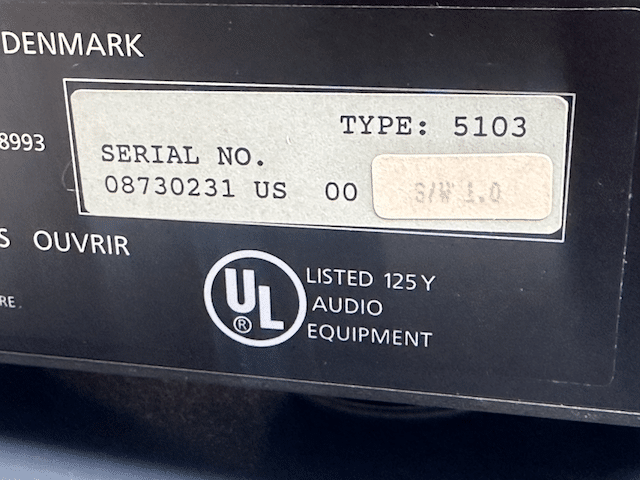
So herein lies my disappointment. the Sony CDX-A20 is designed to be used with a head panel on a vehicle dashboard, and has a dedicated pin for transmitting CD data to a display. But I get zero status on any B&O controller or Powerlink speaker- a wasted opportunity for a reasonable integration solution, which would have taken only a minimal effort to program.So there are a few places yet to explore for some definitive answers as to where any fault in the status reporting may lie. 1) Check the Sony data-out line for a signal denoting the sending of data. If present, then either 2) the B&O firmware is not responding as expected, or 3) hasn’t been programmed to pass on the Sony display status data via Datalink. My unit has firmware version 1.0 – I have seen a picture of a 5103 controller with firmware version 1.1, but without more knowledge, I cant speak to what changes are included in the later revisions of the controller.
Given the CMM-10’s limited integration, I can’t imagine that these sold all that well. For starters, the use of Datalink ’80 as a control protocol means that the CD changer has to reside reasonably close to the Beomaster, with it’s own exclusive 7-pin connection tied directly to the Beomaster in order to function, instead of in a cabinet somewhere, perhaps in another room – IMHO a clear limitation that lies in the chosen implementation. To me, any perceived market need by B&O was an opportunity to put a DL’86-enabled unit (or series of units – up to 7 total!) on the Aux MCL, and have it addressed via the Source “Unit” designation that the DL’86 protocol was designed for.Perhaps they were simply intended as a stop-gap solution for those customers who asked for multi-CD changers for background music, or commercial customers who simply wanted an un-managed 10-hour playlist. If anyone has more information on these strange-and-likely-rare-for-a-reason units to help me better understand the what/why/when/where of their genesis, feel free to add to the discussion.-
This reply was modified 1 month, 2 weeks ago by TK.
1 June 2026 at 02:03 in reply to: First look – CMM-10 type 5103: a 10-disc CD changer from 1990 #123790TKBRONZE MemberAfter some gentle prodding of the main elevator gear, I managed to free the elevator from the grease-turned-glue that had bound it in place, and the unit began responding to ‘Tape Play’ commands. By ‘responding’, I mean it would pull out a CD and position it correctly, then fail to detect that the step had completed properly, and promptly return the CD to it’s holder. It would next raise the elevator to the next CD in sequence, and do exactly the same thing again, until it had gone through all ten slots, without playing a single CD. At least there was some progress.
After verifying the function of the light detection sensors, I began looking for some kind of mis-calibrated spring-loaded switch, or some other sensor that I had not yet seen. A bit more fiddling led me to the discovery that when I positioned the player in the upright position (remember from earlier that it can be mounted in 2 main positions), the sensors correctly detected the CD and promptly lowered it into position over the laser and began to play it – the unit was now working!
… ‘Ish’. Clearly I’m going to have to examine the capacitors and adjust the laser strength/focus, as some of the CDs were prone to skipping and/or getting stuck on sections of the CD. I’ll have to do some research on the laser adjustments for these Sony lasers, and find out of they are prone to the same issues that plagued the old Philips servo boards. My initial examination of the capacitors revealed a few familiar Sanyo units, which I tend to replace in the Beolink 7000 units.-
This reply was modified 1 month, 2 weeks ago by TK.
TKBRONZE MemberI also came up with a better version of the motherboard upgrade for early 5005 and TX-2 boards to prepare them for Datalink use, by placing the 10K resistor in the same location that it appears on the 5500 and newer boards.
I first drilled a hole for the resistor.
Next, I placed the resistor and transistor in their proper locations, taking care to leave the legs long, so I could connect them later under the board. I didn’t make any changes to the transistor placement from the last iteration.
Last, I connected the legs of the resistor and the transistor base, followed by a protective heat shrink cover to prevent shorting.
-
This reply was modified 1 month, 4 weeks ago by TK.
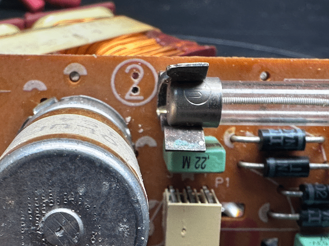
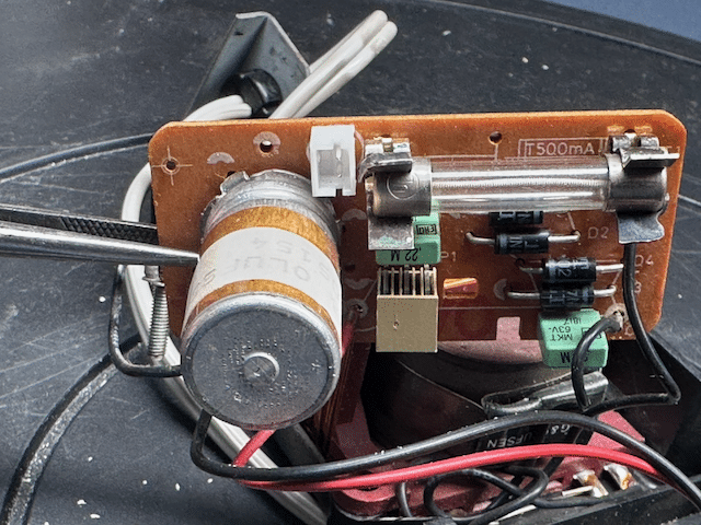
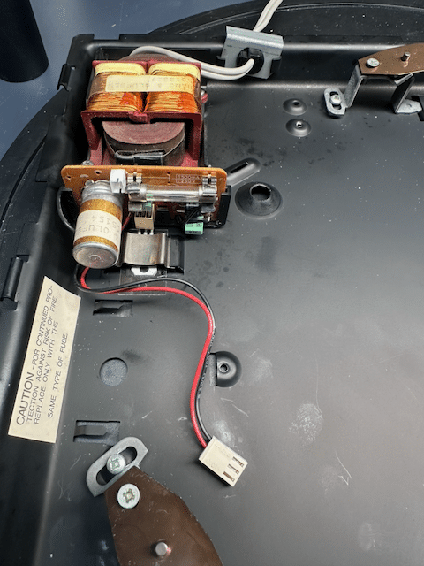
TKBRONZE MemberThis go-around, I thought I’d take a stab at creating a plug for the RIAA right on PCB2, like the original. After checking all the caps and diodes for function, I drilled 2 small holes with a 1.0mm bit using a hand drill. It’s a tight squeeze on a US-Spec power supply, due to the long fuse which occupies the space normally reserved for the plug. Thankfully theres an adequate space over the PCB label, where there are no traces to damage.
I added a dab of crazy glue to the backside of the plug, and placed it in the hole. So far, so good!
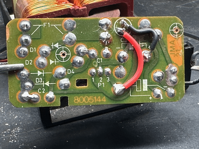
The rear side required 2 wires. I decided to stick to my convention of keeping the red wire at 12V, and the black wire at 25V.
After checking all connections for connectivity and shorts, I was ready to insert the power supply back into the chassis. I replaced the regulator IC for good measure, as the installed one was reading 11.7 volts – it probably would have worked fine, but the new one was bang-on 12V. Although I have a few NOS barrel capacitors, I elected to keep the original in place, as it was reading a healthy 1100uF / 0.47 ISR, with no signs of leaking. Another step complete.
-
This reply was modified 2 months ago by TK.
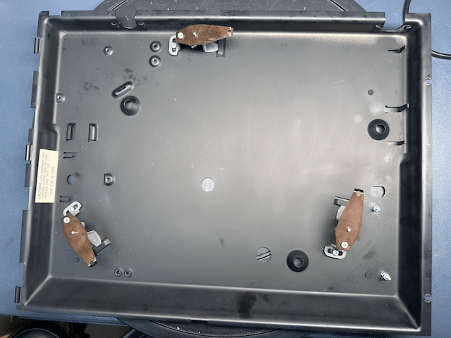
TKBRONZE MemberAnother day, another upgrade. This time I’m taking a Beogram 3000 and upgrading it to Beogram 4500 specification. I got this unit because I thought it would fit in stylistically better with the black 7000 series that I have. My first thought was to simply replace the 5500 shell with the 3000 shell, but I decided to leave well enough alone – the 5500 had the latest motherboard with the discrete standby function, which the 3000/4500 could not make use of, because it lacks a front face.
I started with the chassis. Some new feet and touch-up paint to cover up the deep scratches.
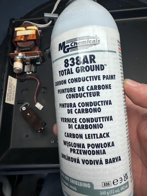
I’m using graphite-infused black paint, in order to keep all areas of the base conductive. It’s not a perfect match, but IMHO better than exposed bare metal. My hope was to eventually use this conductive paint as a new semi-black coating for the platter, but that will be a bit later when I’ve experimented a bit with it.
17 May 2026 at 20:50 in reply to: cd6500 unable to propery adjust laser mV (and other issues) #123645TKBRONZE MemberJust an update to close this out – after a few days of taking the laser apart and reassembling, and making several adjustments, it appears to be working now. Near as I can tell, the laser assembly was at some point jarred and was unable to travel through its full range of focus. The act of disassembly/reassembly has freed it, and now it works properly. This has also resulted in fixing the issue of R3142 getting hotter than usual. I’m still wondering if there are other weak components on the Servo board, but I’ll take the intermediate win and call it good for now.
Just a comment with respect to what I’ve seen elsewhere and on other more experienced channels with Philips repairmen – adjusting the Laser and focus pots are fairly straightforward if you have the proper tools to measure the results. As a general piece of advice I’ve discerned- if you don’t know if the system is set properly, start in the counter-clockwise position first for the laser power, and sssss-lo00000ow-ly tick it to the right, just a slight nudge of a few degrees at a time, and allow the reading to stabilize before making further adjustments.
Also a curiosity, I discovered that some working Philips laser components and servo boards are occasionally worth considerably more than the cost of an entire Beogram CD player. There’s a real fondness for the TDA1541A among enthusiasts, who praise it for its “analog-ness”. I had not considered this when I first started fiddling around with these players. It’s akin to “buy the stylus cartridge, and get the turntable for free”.
TKBRONZE MemberMy understanding is the same as @Madskp – there is no “on-off” single voltage signal as there is on a Powerlink system.
If I have time tomorrow I’ll check and see if the 3500 will respond to a few commands sent via Datalink. I’m now wondering if I mis-remembered activating it using Datalink, or a Beo4, and then just mistaking the data as being a relay of Beo4 commands from the 3500 over MCL2. The talk about needing the timer to be active makes me think it is not programmed to respond to all generic MCL2 commands via the Datalink pin.
That said, since the 3500’s IR channel is also MCL2, if my experiment fails, there’s probably a way to inject incoming Datalink signals via the IR gateway – without scouring over a schematic, Id imagine thats probably more trouble to engineer than it’s worth.
TKBRONZE MemberJust based on my own limited experiments, the 3500 does decipher and respond to Datalink 86 (MCL2), at least to an extent. Penta status updates seemed to provide 3500 screen updates. and I think I recall an On/Off trigger. At this point I stopped looking at it. Also of note, there is no “5V” injection option here, as there does not appear to be an “active” pin or similar that one sees on a proper Powerlink speaker. So to have any chance to wake up the speaker via ML/MCL, one would need to address it appropriately- for example using a properly formatted MCL2 command.
In my limited testing, I seem to recall that I could send an MCL2 signal to turn it on and off, and update the source on the screen. I don’t recall if I could send MCL2 that would manipulate the volume. I spent a total of 10 minutes on it, so my memory may be a bit hazy.
All that being said, I do not know which 3500 firmware version- if any- is coded to respond to a signal to control ALL of it’s features (On/Off, VolLvl, Mute). The 3500 I have at the shop is on FW 1.0, so it may fall into the “not yet implemented” category and not indicative of the later variants.
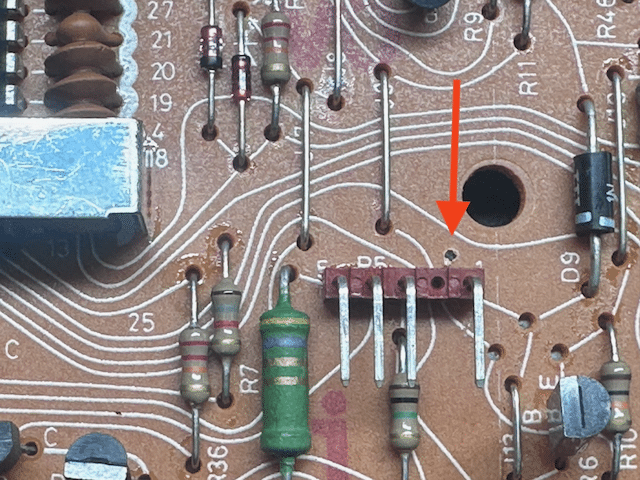
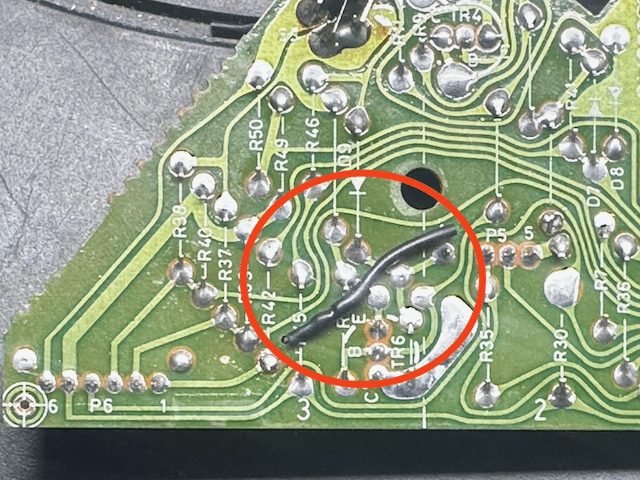
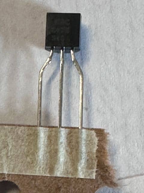
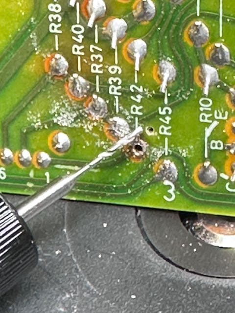
TKBRONZE MemberI’m restoring another 5005, and I elected to try another technique for retrofitting a TR11 BC547 transistor into the datalink path of PCB1.
I started with a new BC547 transistor I bought from Mouser. When looking at the flat face, the pins from left to right arre (C) Collector (B) Base and (E) Emitter.
I unsoldered R42 on the side nearest the I/O cable, and drilled a small hole 2-3cm from it, taking care not to pierce any existing traces, or the adjacent R45 resistor.
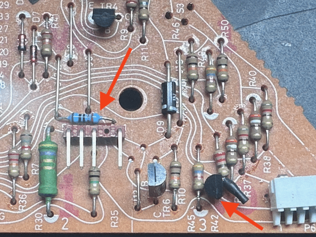
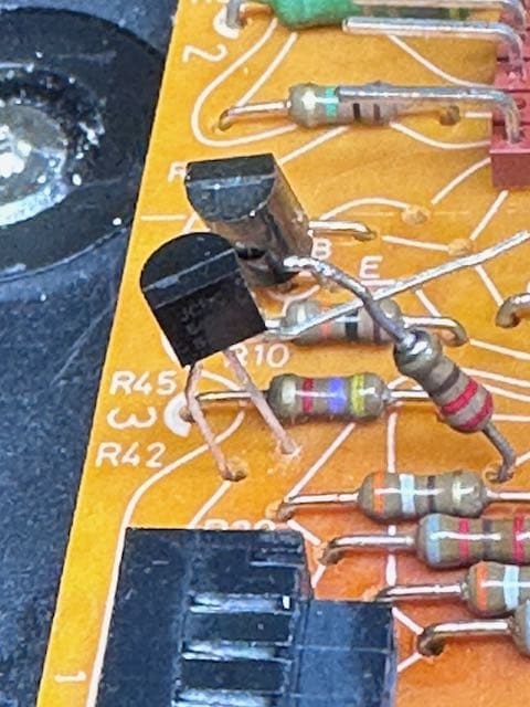
Next, I took the BC547 and placed the (C) pin through the vacant R42 hole, and the (B) pin through the newly drilled hole. I bent the (E) pin towards the R42 resistor.
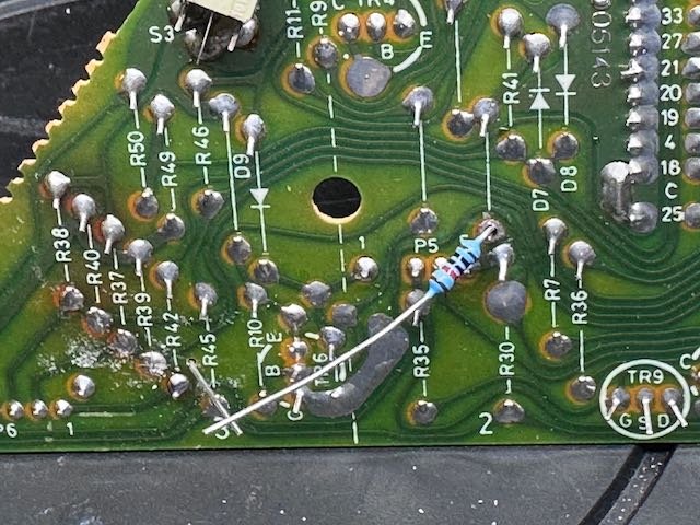
Turning the board over, I unsoldered the jumper adjacent to R30, and squeezed a 10K resistor through the hole. Theere was just enough room to have both the resistor and jumper in the same hole, which I resoldered in order to make a permanent connection.
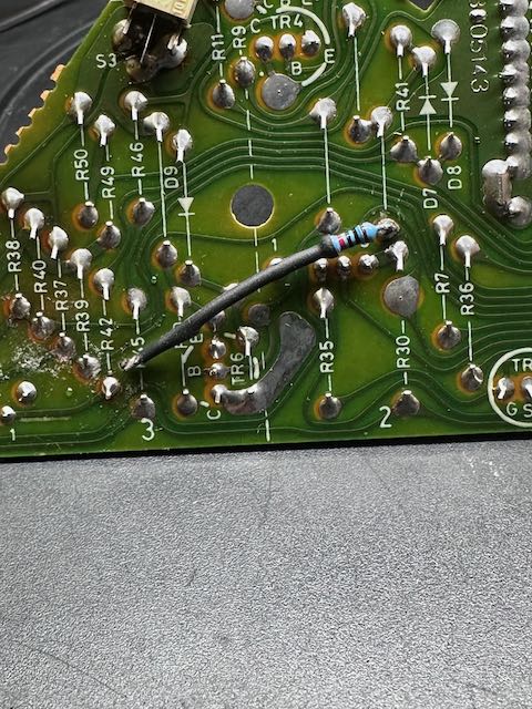
I covered the resistor lead with heat shrink, and soldered the end to the (E) pin of TR11. This heat shrink is just a security blanket to prevent future shorts on the board.
I finished with attaching the TR11 (E) pin to the R42 resistor, and covered the end with a piece of heat shrink. IMHO, this looks much nicer than the other solution.TKBRONZE MemberDo the two red LEDs on the volume bar light up when you turn the knob, and you just don’t see any green volume level indicators? Or do you truly see nothing at all – including the two red LEDs – when you turn the volume knob.
What if you play a tape, and hit the FF button – do you see the lights strobe in one direction?
What if you try to set the bass level – anything light up then?
The volume knob has two inputs, as you have discovered. The micro switch’s role is to simply let the processor know that the knob is being turned, and which way it’s turning. This alone would trigger the two red LEDs. The green LEDs signifying level are controlled by the optic sensor.
If the LEDs dont illuminate when you hit FF (or bass or status), then Id venture to say that your issue does not lie with the wheel sensors, but elsewhere in the circuitry.
If they otherwise light up given the inputs above, but you are not even getting any red LEDs when you turn the knob, I’d take that to mean that the CPU is for some reason not being told that the knob is turning via the microswitch, and then you would likely not get any green level LEDs displayed anyways. The microswitch basically facilitates a pull-down of the pin to ground, and that is fed directly into the CPU, so if it has continuity then there’s not a whole lot that can go wrong, apart from the possibility that its not grounded properly.
If the two red LEDs do illuminate, but you are not able to adjust the level, then that point to the opticoupler circuit,which contains a few transistors and an opamp in addition to the opticoupler, which can also be a possible failure piont..
11 April 2026 at 15:57 in reply to: Connecting a BeoMaster 5500 to a Beolab 2 subwoofer and Beolab 3 speakers #123278TKBRONZE MemberI don’t know that Sounds Heavenly sells to anyone outside of Europe, just based on his site. It does sound like you have a few skills with a soldering iron, so you will likely be able to fashion something together that will work.
I have a topic that touched on some of the information you seek, which likely could benefit from a bit more clarity on how to accomplish the task of adding Powerlink to a BM5500. There are other discussions as well. I’ve included the link below.
Do you have any unused source receptacles on your BM5500, apart from Phono? If yes, then you’ll have access to pretty the audio and control signals you need to make a Powerlink output – although I have not researched whether the “sensor on” pin will work as a “power on” signal. There may be one or two signals that will require you to add a jumper cable to the BM5500 I/O board in order to have it work properly.
The process I was considering in order to prototype the Powerlink output was as such:
- Buy a fully wired Din-8 cable
- Remove one end plug
- Strip back the cable cover 6-12″
- Attach pins to all the individual wire ends (using barrel-style contact pins from Amazon)
- Insert the individual ends into the appropriate pin locations on the BM5500
- See what happens
I’ll give this a try next week and post results on the thread below, with the exact pin-outs that I used.
-
This reply was modified 1 month, 2 weeks ago by
-
AuthorPosts