Forum Replies Created
-
AuthorPosts
-
pilatomic
SILVER MemberGood evening,
Sorry for letting that many days go by without updates, I originally planned to write last week about my avancement,
but I caught the covid in the meantime, and while the novelty factor has dry out, the fever is still quite effective.Anyway, I’m now back on my feet (mostly), so here are the news :
Following B3OHACK3R’s concerns about the usage of tantalum caps, I went looking for other regulators that would be stable with ceramic caps.
I found a new Texas Instrument part, the TLV761 : it is stable with output ceramic caps, has a lower Vdrop and a better PSRR than the LM1117 I originally selected,
which both means less noise when used on a noisy USB-C supply. Bonus points, it is pin compatible with the LM1117, and comes with a soft start function ! Perfect !
I’ll be using those with cermic caps from now on.I did make some (rough) measurement of the PCM5102 DAC using my PC soundcard input to investigate the impact of changing the value of the output filter resistor.
Going from 470R to 100R produces a small (around -6dB) improvement of a bit of 50Hz present in the output. But that noise was already at a ridiculously low level (-90dB).
I reckon it lowers the output impedance of the system, making it a tiny bit better at ignoring the 50Hz ambiant noise ?
The improvement seems ever so small in my case, I don’t think I’ll implement it.I also spent a bit of time working on the firmware. I does now identify itself as a USB CDC device when plugged to a computer,
which means you can connect to it with a terminal emulator (such a Putty), and get a command prompt.
Only 3 commands are supported now : querrying the firmware version, querrying the device bluetooth name, and setting the bluetooth name.
That means if you have multiple Beotooth, each one can be named to reflect the system it connects to.
More commands might be implemented in future firmware versions.I did mill about a dozen enclosure, and the result is even better than the first I did, so now I have everything required to build the first few Beotooth.
I’ll be writing to those who sent me messages as soon as I am ready to ship theirs.Wishing you all healthy holidays !
Location: France
My B&O Icons:
pilatomic
SILVER MemberOnly noticed when measuring a PCM5122 on the audio analyzer (pretty much the same chip on the analog output).
Would you happen to recall the output load characteristic during that test ? Having a relatively low (~1k) load impedance could definitely degrade that THD.
You mean 100 uF, right?
No, really 10µF. That’s what the LM1117 is characterized with (the 3.3V fixed version, not the ADJ one). It requires the output cap ESR to be > 0.3R, which already excludes ceramic caps.
Location: France
My B&O Icons:
pilatomic
SILVER MemberYou could evaluate lowering the series resistance of the RC filter on the PCM5102 output a little. Otherwise you won’t be able to hit the THD+N value they are mentioning in the datasheet. Some TI reference designs are….
That’s interesting ! Any insight on the mechanism that lowers the THD here ? Too much drop through the resistors ?
Someone in love with tantalum caps? ? .
Oh yeah, I really like their yellow color ! Joke aside, I’m using the venerable LM1117 LDO to provide +3.3V rails, and the recommended output cap is a 10µF tantalum (that’s also a TI design), so ceramics probably lack enough ESR to reach stability here. Used here as regulator outputs caps, the dV/dT is no issue, 16V caps on 3.3V rail, and with low current (0.35A) polyswitch on the supply (and a 6V TVS), I’d say we’re in a correct configuration for tantalums caps, don’t you think ? 🙂
Bonus point is virtually no aging, and no microphonic effect (but that’s a bit of a moot point when used as decoupling caps).Location: France
My B&O Icons:
pilatomic
SILVER MemberHello Beoworlders,
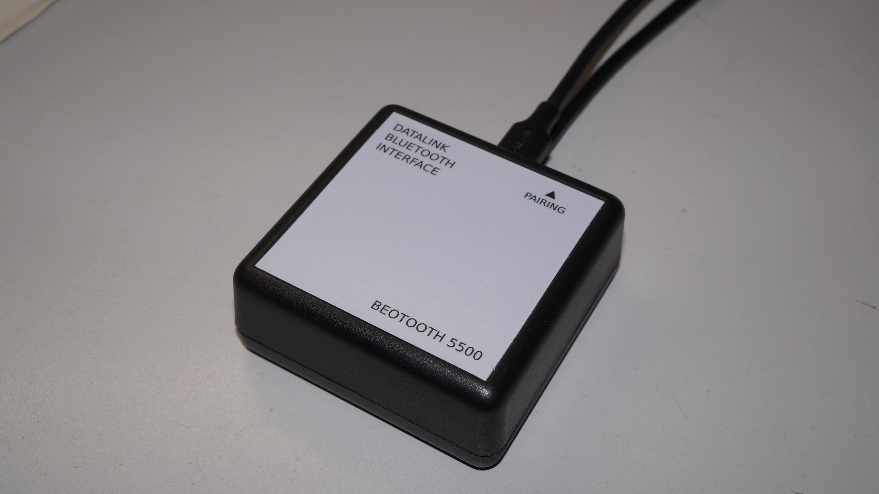
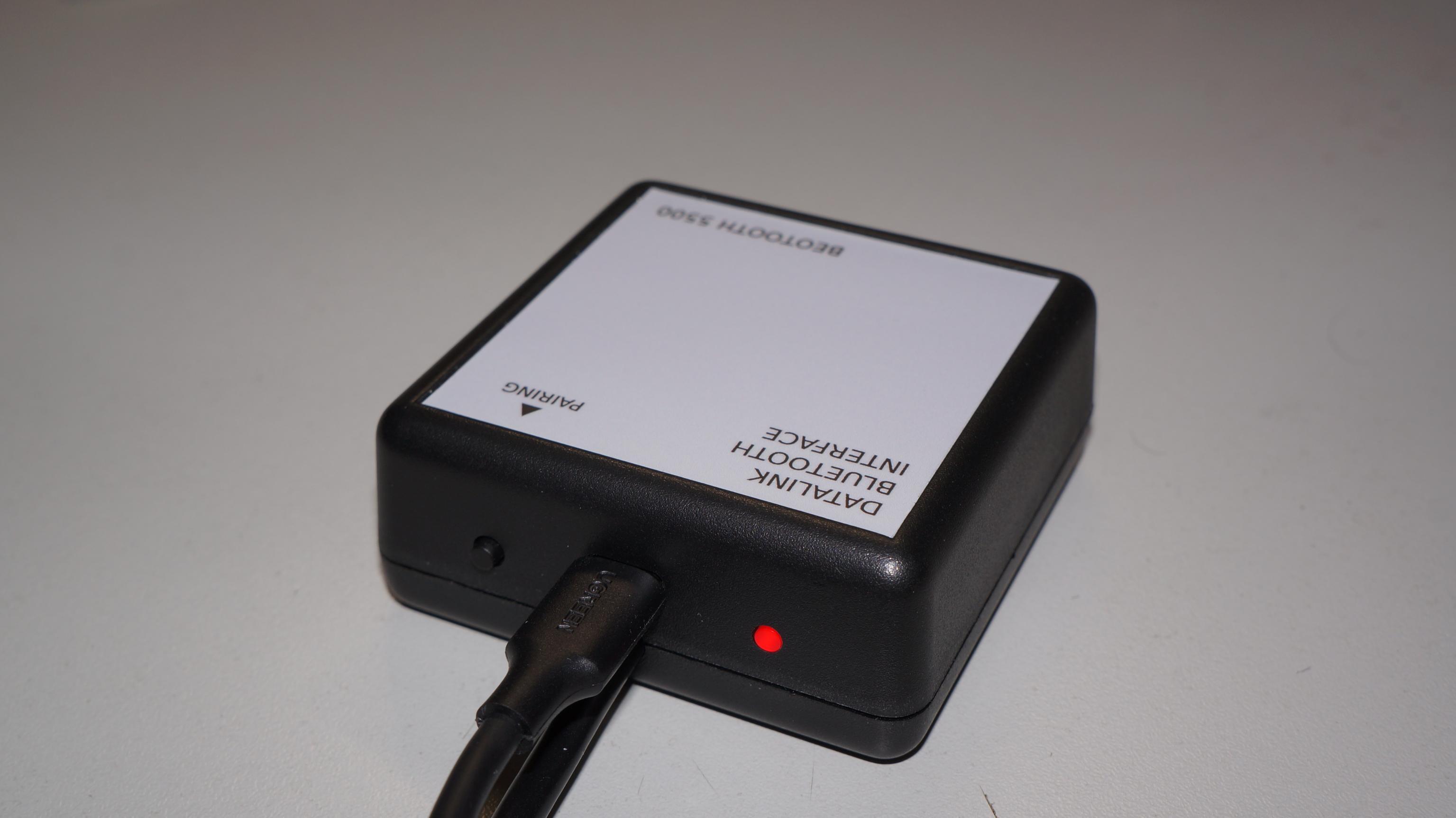
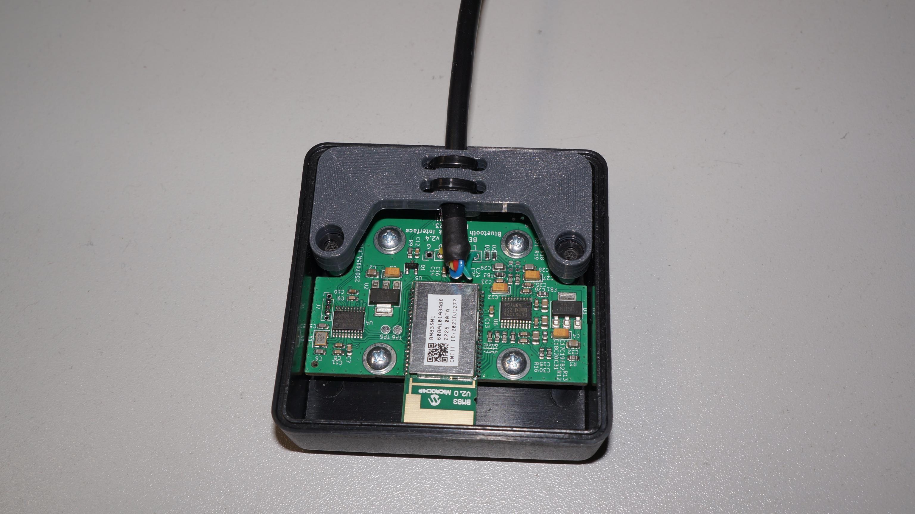
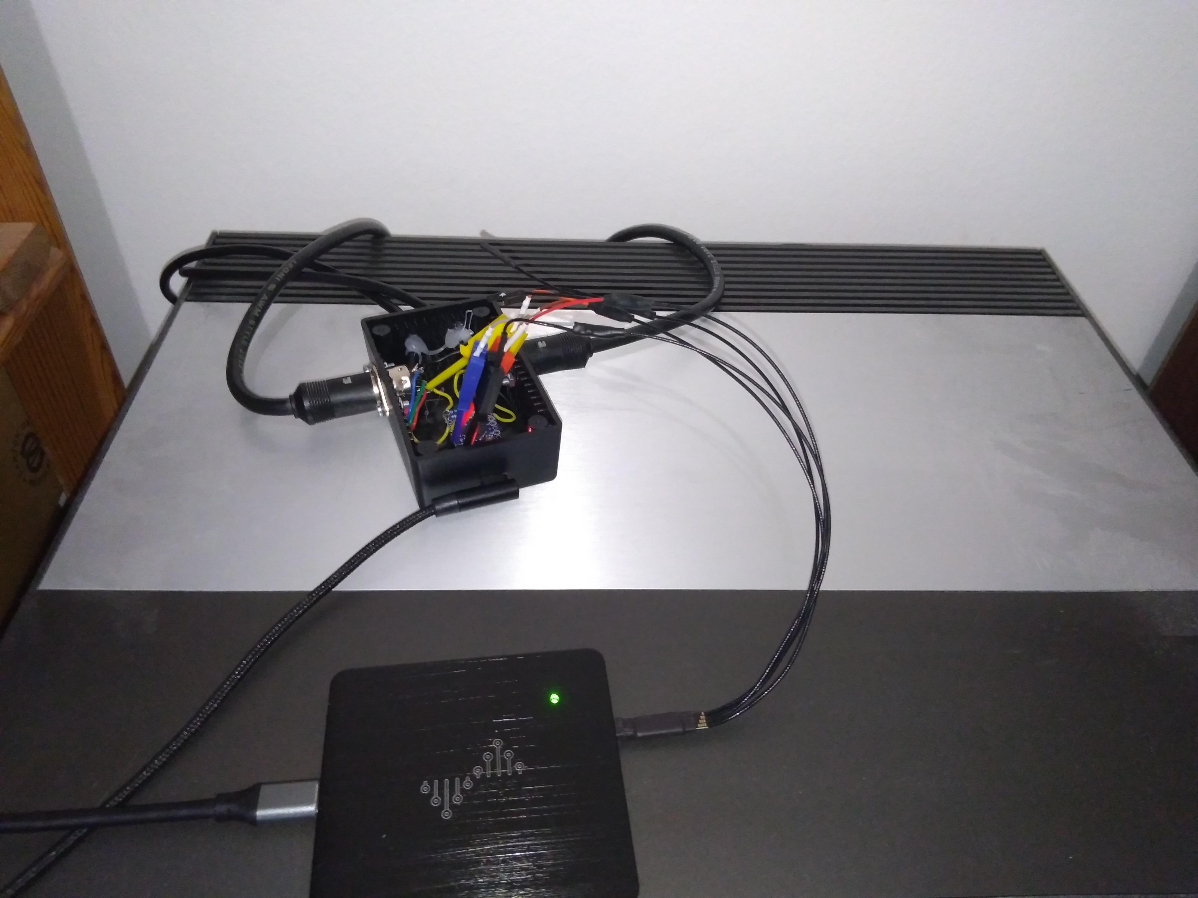
Weeks went by, and this project is now reaching completion. I have received the new PCBs, and got myself access to a small CNC machine to mill the back of the enclosure, so that I’m not ashamed anymore of showing that side of the device. I have also made properly sized labels (the previous ones were too small), and designed and printed a cable holder, that ensures any mechanical strain on the cable is transferred directly to the enclosure rather than ripping the wires off the PCB.
This version does support a USB firmware upgrade process, so that both the MCU and the BT module firmware can be upgraded later.
I also came up with a pricing scheme. My intent is to offer those mainly as kits, only requiring some beginners soldering skills to assemble it. A kit would include :
- A PCB fully programmed, missing the red LED.
- The red LED. (As it is easier to have it flush with the enclosure when soldering it after mounting the PCB).
- Around 80cm of 4 conductor cable.
- The DIN-7 connector.
- The enclosure with properly machined holes, and all screws.
- The cable holder part, with 2 zip-ties.
- The adhesive label.
- The pricing would be 80€ (ship. Excl) for a kit, and 115€ for a fully assembled device.
I still need to spend a bit of time tweaking some features, notably I am looking at a way to change the device Bluetooth name, so that you can have it match the system it is connected to.
Lastly, I have everything needed to build a few kits, except I need to order new enclosures, as I ruined the few I already bought honing my CNC machining skills (no wonder machinist is a real job, who would have thought !), and only the last one ended up living to my expectations.
Based of those 2 points, I expect to be able to provide the first kits in a few weeks. Please contact me in PM if you are interested.
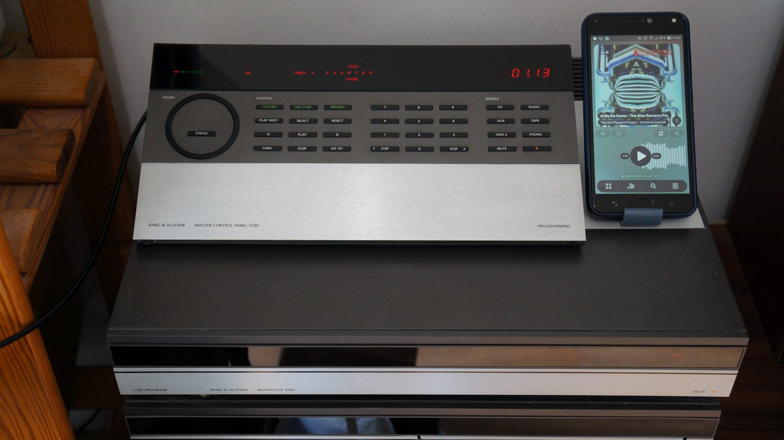
While I work on those last details, here are a few up-to-date picture :
Location: France
My B&O Icons:
pilatomic
SILVER MemberThanks for the picture, that was interesting ! Seems like the microcontroller simply emulate IR commands when it receives a datalink command.
Location: France
My B&O Icons:
pilatomic
SILVER MemberHello Madskp,
Since nobody answered you, I’ll leave my 2 cents here.
The fact it works intermittently would lead me to look first for bad connections (possibly cold solder joint) or power supply instability (out of specs capacitors).
Keep in mind I’m not an expert on those, only had 2 in my hands, with rather trivial issues.
Good luck.
Location: France
My B&O Icons:
pilatomic
SILVER MemberB3OHACK3R wrote:
[…] Somehow DL can only be bit banged. […]Indeed. I meant bitbanging from a SOC, rather than a dedicated MCU.
Location: France
My B&O Icons:
pilatomic
SILVER MemberI had made a custom PCB, and tried playing with the decoupling caps (both ceramic and tantalum, values from 10nF to 10µF), but it didn’t lead to any changes. The fact it only happens when radio perturbations are present lead me to believe that there might be an issue with channels scheduling and / or frontend AGC. (Either that, or my PCB had a very bad EMC susceptibility issue, but being such a simple project, I don’t find that too plausible). Also I did most of the test connected to my Linux workstation, so the issue might be there too. Anyway, I turned away from the ESP32 for that project when I could not get other codec working than SBC, and that was a deal breaker.
I’m not a big fan of bit-banging stuff, not with a full Linux running at least, but it seems you have more experience than me on that subject. My approach would be to delegate protocol handling to a small MCU, and have it communicate with the SOC using a local UART or any other dedicated bus. That way the SOC does not have to care about timings.
Location: France
My B&O Icons:
pilatomic
SILVER MemberAh, interesting that it wasn’t reliable for you with an ESP32. Been using it myself for a couple of projects already and was always happy. Did you use their IDF SDK or the Arduino stuff? Yes, I know those BM83 modules. Around for ages I think and come with a hefty price tag for what they are. Was there a particular reason you just didn’t go with a Linux system? Things tend to be a lot easier then.
The ESP32 is mostly okay (except that awful ADC !). I use it for other projects with the IDF devkit (not that Arduino rubbish), but here it came short on 2 points :
First : Connection stability, especially in bad conditions (mostly occurring here when my wool sweater generates a bit of static electricity, that was a guaranteed loss of link with he ESP32). Does not happen often, but losing link even for a few seconds every couple of hours is very noticeable on a audio stream.
Second : Not having a working implementation of a good audio codec (ESP-IDF only comes with the Bluetooth standard SBC codec, and you can definitely here the compression). Some third party have tried porting AAC, which kind of work when using the second CPU to perform the decompression, but it does still have some dropouts from times to times (maybe caused by bus contention due to having the 2 CPU working heavily on RAM data ?).
The BM83 are indeed very expensive for what they do, but they are typically targeted at this kind of low volume products, and the Bluetooth link has been rock solid since I switched to those (not even one unplanned link drop !). Interestingly, I had rejected those in my first search 2 years ago, as back then their firmware did not support AVRCP. It has been updated since.
Regarding using Linux SOC, it definitely was an option. I did not go that way mainly because I am more comfortable with bare metal development, and I do not trust the completeness of the Bluetooth Stack on Linux (AFAIK it is based on a old version of the Android BT stack), I don’t know if AVRCP is properly implemented. Also I like using the simplest tool for the job. And going with a module with integrated antenna almost guarantees EMC compliance by following good practice PCB design, that’s also a plus.
An idea to make it more simple for you could also be to just sell the working PCB and inform what enclosure you have used. I guess for many people doing the mechanical assembly themselves would be an ok compromise.
That’s actually a good idea ! I’ll keep it in mind !
This looks like a great project. I’m looking for something like this with airplay 2 streaming – I guess that is a completely different technology to Bluetooth?
Indeed Airplay is quite different AFAIK, as it requires a proper IP connection (WiFi).
Location: France
My B&O Icons:
pilatomic
SILVER Member[…] it would potentially work with any B&O master/system with a datalink-based A.Tape input port…..as I assume.
Indeed. I have also tried it with a Beosystem 2500 where it works nicely, providing controls from the Beosystem and its remote, and automatically turning it on / off. Btw it works on A TAPE but also TP2 input (except that on the BM5500, you loose the live status display when using it on the TP2 port).
Absolutely stunning development. This is Beoworld! Thank you, tank you, thank you! Except for the name… BeoTooth? Honestly, it scares me like an MLGWNL (whatever) box profoundly dug in my human body. Jokes apart, you just made raise BM 5500 prices (jokes not so appart after all…).
Thank you for your enthusiasm, means a lot to me, as I tend to quickly lose my drive after completing a project, and often move to something else without talking much about it. Regarding the name, I know BEOTOOTH sounds a bit cheesy, but it does match the beo* pattern, and it’s cheesy enough that I shouldn’t get in trouble with B&O for using it. If you have a better name in mind, feel free to propose it, nothing is set in stone yet !
Nice, congrats! Which BT chip are you using?
I did a proof of concept about 2 years ago using an ESP32, but couldn’t get a reliable sound stream with anything other than the default SBC codec (which really isnt that good). I then attempted to pivot to Qualcomm chips, but they are really interested in small volume orders. I ended up using the Microchip BM83 module, which works quite well for my use case, except for its really arcane documentation !
[…] ( I guess that it is other than the BS2500 where this applies?) If it only is a hobby project and you dont want to be a manufactur /seller of these units […]
Indeed status display is only on the BM5500 as far as I know (not too familiar with the entire B&O lineup from that era). But control features works on BS2500, so they should work on any Datalink compatible device, and I have yet to test it with my BS9500 (which is currently in storage).
VERY nice! I’d be surely interested in buying (either pre-made or kit-form, latter preferred) at least a couple!
I’ll see what I can do regarding a kit but I think the only solderable item left would the wiring to the datalink connector. Would that still count as a kit for you ?
Lovely, count me in as well if the price is right.
I will try selling it with the same terms as my Beolink 5000 E-Paper kit, and see how it goes. I haven’t determined a price yet, as there are still some things that needs to change from my prototype, and things I have not taken into account, like proper machining of the connector slots in the enclosure (I really prefer not to show the back of the prototype enclosure, with its very DIY knife cuts), buying the proper screws (my random screws box won’t be able to provides another set of matching screws) and determining the actual assembly time required.
Thank you all for you interest ! I’ll keep you posted
Location: France
My B&O Icons:
pilatomic
SILVER Member(Is the MCP showing the elapsed time of the playing source? – they are only one second apart)
Well observed ! The slight difference is due to the playing app on the phone, and unrelated to my project.
I’ll open a new thread soon with all the details 😉
Location: France
My B&O Icons:
pilatomic
SILVER MemberSneak peek at my ongoing project !
Location: France
My B&O Icons:
pilatomic
SILVER MemberCan confirm, currently hacking around with what I believe is the Datalink 86 protocol on my Beosystem 5500 ( so CD / TP / TP2 / PHONO ). TP and TP2 protocol are identical, except that TP2 has no support for running status (to provide the MCP5500 with live display).
CD and PHONO also seems identical, but I haven’t pushed the investigation enough to confirm that.
Location: France
My B&O Icons:
pilatomic
SILVER MemberStunning result you have here, congratulations !
I am very curious about that enclosure ! Is that something you designed ? Or is it an off the shelf part ?
Full disclosure here, I have an ongoing project that bears some resemblance with yours, but I have already settled on an more conventional enclosure.
Location: France
My B&O Icons:
pilatomic
SILVER MemberThank you for the links. I indeed had a look at them, but it turns out they are not comprehensive enough for my use case.
I will of course post my progress here, once I reach a point where I have enough to show to justify a dedicated thread.
Location: France
My B&O Icons:
pilatomic
SILVER MemberSlowly reverse engineering the Datalink protocol used between the BeoMaster / BeoCord / BeoGram 5500, for a secret project.
Location: France
My B&O Icons:
pilatomic
SILVER MemberThat one is on me, it seems I was mistaken in my previous message : RL1 has NC contacts, so disabling the relay just kept the amplifier powered. The relay needs to be energized to turn off the supply to the amplifier.
This could normally be done by shorting the collector and emitter pins of TR19, but it uses the same 8V supply as the display LEDs, and since those don’t work, we can not rely on that supply still operating, so let’s not do that.
It’s been a while since I worked on mine, I don’t remember if P23 can be unplugged ? If so, unplugging it will prevent any power going to the amplifier (for real this time). The downside is it will also disable the 50/60Hz signal going to the CPU, and I don’t know if this signal is only used for time keeping, or for other purposes.
Once you’ve done that, you should check that the display is operating normally.
Not having the proper schematics certainly won’t help, that’s for sure, but I don’t think there is any irreplaceable parts in those models except for the ROM and maybe the transformer, so it’s most definitely fixable.
Seeing how the magic smoke escaped from the amplifier area, you might simply have a shorted output transistor (and the blown power resistor of course).
Location: France
My B&O Icons:
pilatomic
SILVER MemberHello,
I’m a month late, but if you are still looking for advice,looks like IC 1 ( display driver ) is having trouble. It is also in charge of producing the control signal for RL1, the relay that switches power to the amplifier. I’d bet thats the relay you hear clicking, and that’s the cause of the burnt traces (each times it closes there is inrush current charging the large C6 / C7 capacitors)
I’d start by removing R34. That will prevent RL1 from closing, hence cutting power to the amplifier. That should avoid any more damages in that area.
Then, look for issues around IC1
Location: France
My B&O Icons:
pilatomic
SILVER MemberHello Emma2,
I have contacted you by PM.Best regards
Location: France
My B&O Icons:
pilatomic
SILVER MemberHi Martyn,
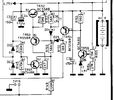
I don’t have this issue with my MCP5500, but I’ve starred at its schematic for some times for another project.
4.75V accross R149 seems quite high, as that would imply about 8V of battery voltage.
Can you check that resistance of R149 is indeed 100k ? ( that might require desoldering one of its legs ).
Location: France
My B&O Icons:
-
AuthorPosts


