Forum Replies Created
-
AuthorPosts
-
 MadskpGOLD Member
Regarding that volume issue was more thinking of a stand-alone scenario where you are using the AAL port to feed an external source into the music system. Then you would have to deal with two independent volume controls – unless you could send a certain local volume command via DL before playback starts.
Just got me thinking of this thread https://forum.beoworld.org/forums/topic/beolink-passive-ir-eye/page/3/#post-20843 where I tested an MCL IR eye connected to the AUX connector of a Beomaster 5500 and was able to control it via the IR eye. So based on that volume control via datalink should be possible. I don’t have the Beomaster 5500 anymore, but can try to do the test with a Beocenter 9300 and Beomaster 4500 and see if it works the same.
Location: Denmark
MadskpGOLD MemberObviously you can do everything that is also possible in an option 2:0 setup with a (2-way) video master.
That makes sense. A beomaster/beocenter in option 0 should be able to get all remote commands from a connected tv in option 2 via datalink
What I currently don’t exactly know is if it’s possible to send local control commands like volume, treble, bass etc. via datalink in an option 1 setup. Haven’t looked into that yet.
Yes thats interesting if the Beomaster/Beocenter does not react to all commands on datalink if it is in option 1
.
Location: Denmark
MadskpGOLD MemberSneak peek at my ongoing project !
Very interesting what this is about 🙂
Location: Denmark
MadskpGOLD MemberYou would have two independent controls but could probably work if you also send a DL command to set a fixed volume.
Most Beocenters/Beomasters have the ability to store a preset start-up volume, which should alleviate this problem.
But also very interesting if it actually is possible to send such things as datalink commands.
@B3OHACK3R do you have some kind of overview of what actually is possible to do with datalink commands besides the obvies like play/pause, stop, standby, fw/rw and so on?Location: Denmark
MadskpGOLD MemberSome use cases for a light version from the top of my head: as an interface to activate a Beolab 2000/3500 or Beolink Active when sound is detected from analog audio input (Airport Express, Chromecast audio etc.)
Another use case that came to mind is an interface to activate the Aux input on a Beomaster/Beocenter with datalink when sound is detected from analog audio input (Airport Express, Chromecast audio etc.). This way source like CD, tape and phone can be controlled with normal operation, but when you wan’t to start music from your phone you don’t need to use both the phone and a B&O remote.
Location: Denmark
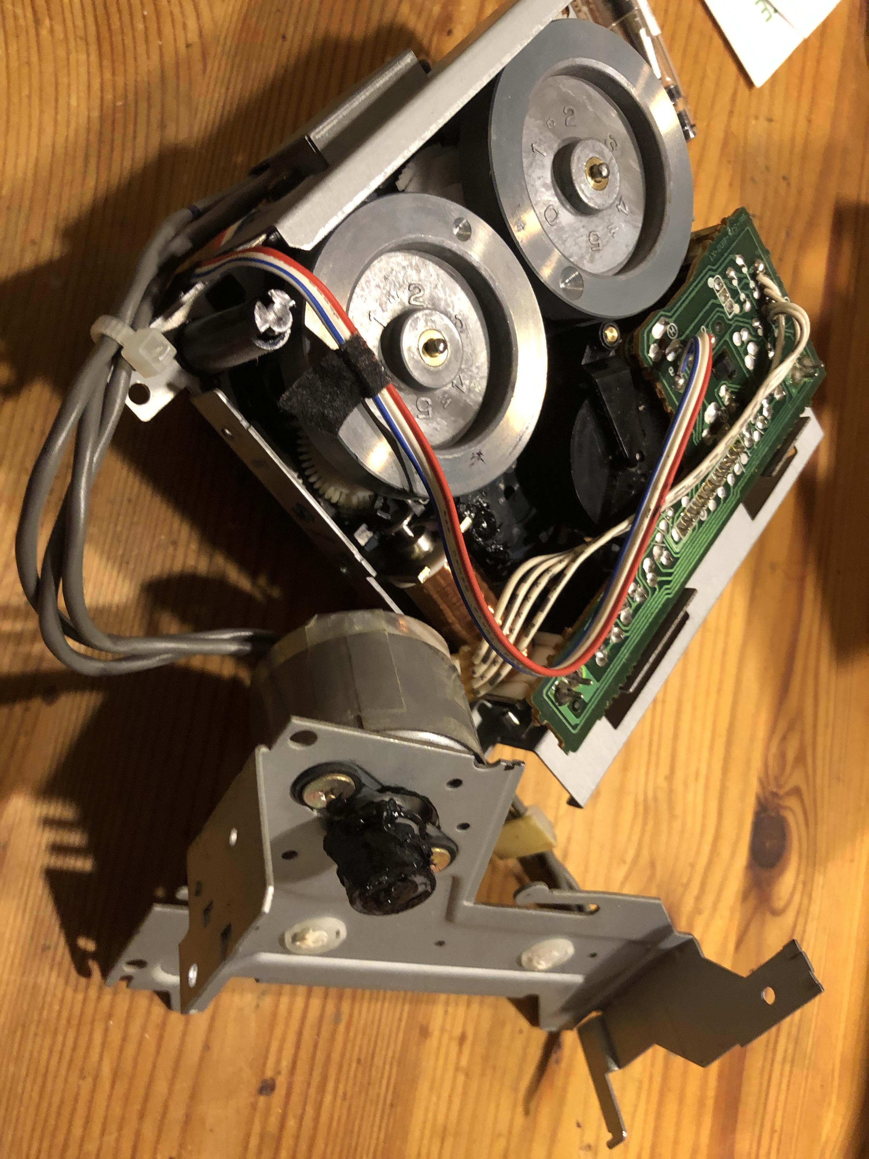
MadskpGOLD MemberWorked some more on it today and got the string for the dooors correct now. It had slipped of one of the wheels in the lower left corner as might be seen in this picture althogh a little dark in that corner.

I have now tried to open and close the doors 10 times without issue and seems to be running as smooth as I remember it did last time I saw one of these in operation.
Also got the casette mechanism back in and it seems to be working mechanically. I have yet to connect a speaker to confirm fully working casette function.
Location: Denmark
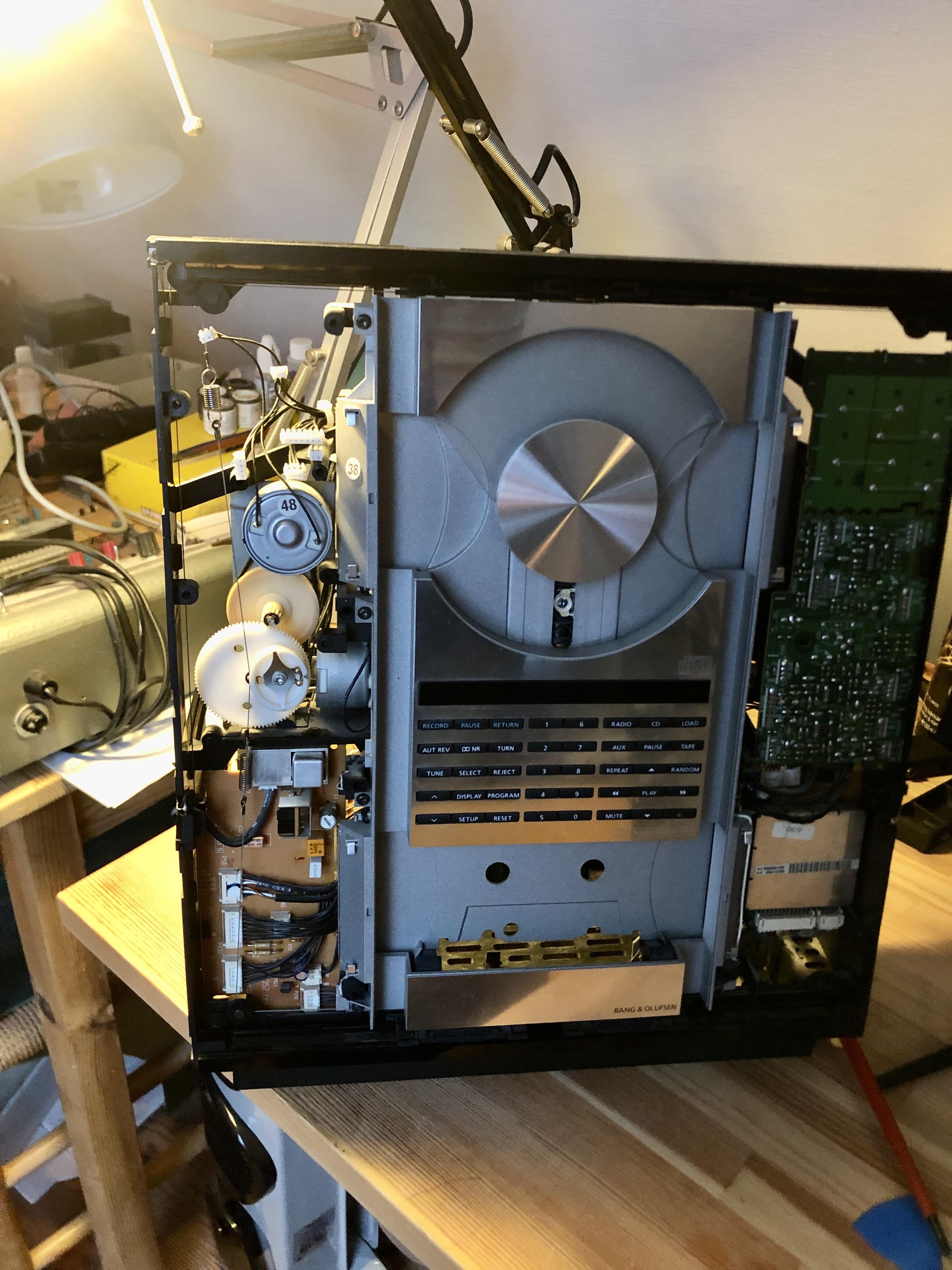
MadskpGOLD MemberI have no started the adventure of fixing this system, and I must say that the BC9300 I recently did a repair on was far more accesible. But of course the design of the ouverture is way more compact.
I started with the belt for the doors and even though I tried to avoid it I ended up having to rewire the strings for the doors. Not entirely sure I got it right as I didnt take before pictured.
Next I got to the casette deck belt. The old one was one chunk of goo, but I think I have it all removed now
Regarding the clamper I will also replace the belt, but I noticed that the arm was not connected to the whell anymore, so one extra detail
Location: Denmark
MadskpGOLD MemberBump just to check the thread is visible to all including non-moderators! Hopefully the first post is back as it should be!
thanks a lot. It all looks like it should after my last edit
Location: Denmark
MadskpGOLD MemberSo to conclude, MCL link rooms can not be extended from the BM4500 while in slave/link room mode.
Location: Denmark
MadskpGOLD MemberNext up I wonder how it will work if MCL2 link rooms are connected to the speaker 2 connectors on the BM4500. I guess there must be some kind of limiting factor somewhere since B&O says that option 6 must no be used.
Have now tried this with the BC9300 as master and the BM4500 as slave still connected via the 7 pin crossed Audio Aux Cable, and a Beolab 3500 MK1 connected to the speaker 2 on the BM4500 with MCL speakerlink cable. The BC9300 in option 1, BM4500 in option 1.6, and the Beolab 3500 in option 6.
Activating radio from the Beolab 3500 will start radio on the BC9300 as the data signal is passed through the BM4500, but the BM4500 amplifier is not activated, and therefor no sound is passed through to the Beolab3500.
If the Beolab 3500 is connected directly to the speaker 2 connectors on the BC9300 everything works as expected. This also applies on the BM4500 if set to option 1.5.
Location: Denmark
MadskpGOLD MemberI have just edited the first post and done a rewrite of the first part to make a better overview.
It seems however no to have diaspeered, might have gone into moderation
Location: Denmark
MadskpGOLD MemberI have just tested again after just over 12 hours of standby – all still working as before! One other thing that I forgot to mention. I tried setting the Apple TV ‘delay before Apple TV automatically turns off’ to 5 minutes and left the system running. After 5 minutes, the Apple TV does turn off but there is no ‘off’ message sent to the TV, so it stays on. If it had switched off the TV then this would have been useful for turning off the ‘system’ after airplay ceases. I suppose you can always set the TV to go to standby automatically instead – I can set the BV10-32 to do so after one hour.
Great observations. I will update the first post
Location: Denmark
MadskpGOLD MemberThat already sounds more stable than the same scenario with the 1gen Siri remote. Looking forward to the overnight result
Location: Denmark
MadskpGOLD MemberSounds like a great test procedure especially the focus on however the connection between the ATV and the Siri remote will be lost after some time as this is s dealbreaker for the relevance of this function.
When you mention that you have to turn off the TV manually can this be done with the remote app on the iphone if the siri remote is placed stationary?
Location: Denmark
MadskpGOLD MemberTrue, thought about this one as well. Not exactly sure if I remember correctly but couldn’t you just use a 1611 converter for using a turntable in a ML setup (Phono / N.Radio source)?Not as far as I know. In all my testing with the 1611 converter it was not possible to control a Beocord (I have never tested with a Beogram, but will try that soon) directly connected to the 1611For good measure I just did a test with a Beogram 2000 connected to the AAL connector on a 1611 converter, and a Masterlink cable to a Beolab 3500.As expected the Beogram did not react to any audio commands sent to the Beolab 3500.Location: Denmark
MadskpGOLD MemberThanks for the update. I added your picture to the first post
Location: Denmark
MadskpGOLD MemberOne use case for both DL and ML could be to actually control a Beogram from a Masterlink only product (BS Ouverture, BC2, BS4, BS5 and Beovisions with ML). Would probably need the use of some alternative source commands to make this work,
A trivial correction, but BS Ouverture does have datalink – you were probably thinking of BS3000/3200 which are ML-only. ? Following the thread with interest …
yes you are right. I am just confusing myself
Location: Denmark
MadskpGOLD MemberCD and PHONO also seems identical, but I haven’t pushed the investigation enough to confirm that.
They are identical enough that the CD connector on a MCL2AV can control a Beogram
Location: Denmark
MadskpGOLD MemberMy take on it is mentioned here https://forum.beoworld.org/forums/topic/beolab-3500-and-1611-converter-settings/page/19/#post-20377
My guess is that the Datalink for Beocord, Beogram etc. Only has 2 device types, and in beomasters with more sockets extra outputs from the Microcomputer is used for these sockets
Location: Denmark
MadskpGOLD MemberTrue, thought about this one as well. Not exactly sure if I remember correctly but couldn’t you just use a 1611 converter for using a turntable in a ML setup (Phono / N.Radio source)?Not as far as I know. In all my testing with the 1611 converter it was not possible to control a Beocord (I have never tested with a Beogram, but will try that soon) directly connected to the 1611, only with a Beomaster, or a MCL2AV. As far as I understand B&O’s termonologi for datalink, there is Audio Link for connection between Beomaster and Beocord/Beogram/CD, and Audio Aux Link for connection between Audio Masters and Video products + the 1611 and 1614 convertersLocation: Denmark
-
AuthorPosts