Forum Replies Created
-
AuthorPosts
-
I finally had the time and all the pieces in one place to test my Beolab 5000 (restored by Frede in 2012) + BM5000 + BV3000s + BV 2500 Cubes + Stereo Width box (+a single CX50 as a center speaker for testing). I’ve bought these piece by piece between 2011-2017. Didn’t really need any repairs other than contact cleaner on switches and new speaker plugs + re-cap of the crossovers on the speakers. These are so heavy 😁 And yes, they do sound very good! I had imagined the stereo width box doing something more exotic (like the Ambiophonic adapter) but still it does make an audible difference and I quite like it.
I didn’t remember that I had the instruction booklet for the Stereo Width box and I couldn’t see it online so I scanned and uploaded into archive.org: https://archive.org/details/bang-olufsen-type-6006-control-box-manual/mode/1up
If I ever had the time to finish up fixing my BG4000 and have it here too…
Location: Helsinki - Finland
My B&O Icons:
Click on SHOW ALL at end, and you’ll get the file listing and the two .BIN files are there. The way archive.org works is a bit convoluted!
Location: Helsinki - Finland
My B&O Icons:
9 January 2026 at 16:06 in reply to: B&O 1983-1984 catalog scanned and cover-recreation for a poster #72462Ha, I was going through a box of B&O parts I have, and found out that I already had the catalog I was looking for, oops 😁
Here’s the finnish cover with some light retouching, for those interested.
Location: Helsinki - Finland
My B&O Icons:
1 December 2025 at 16:52 in reply to: B&O 1983-1984 catalog scanned and cover-recreation for a poster #71619Thanks matador, this is already the best quality scan I’ve seen of that cover. I’ll see what I could do with it.
Location: Helsinki - Finland
My B&O Icons:
Only a B&O-product would talk Beolink, and make the BC to start from an input, it won’t start by an incoming audio signal only.
Do the other input or the standby touch-button work? Can you test it in TAPE2? The glass panel with the touch-buttons might be loose (due to aging of the double-sided tape that holds it into the frame) and the glass might have lifted on the edge of the glass panel causing the touch-buttons not to work (or needing a stronger push to first push the glass panel back down to the original position).
Location: Helsinki - Finland
My B&O Icons:
29 November 2025 at 21:43 in reply to: B&O 1983-1984 catalog scanned and cover-recreation for a poster #71588I was perhaps exaggerating talking about posters, I meant just something printable in about A4 size, which would look neat in a simple frame (like the one I did). Just a high-res scan in something reasonable resolution would be nice.
Location: Helsinki - Finland
My B&O Icons:
25 November 2025 at 21:09 in reply to: B&O 1983-1984 catalog scanned and cover-recreation for a poster #71553Sure,
here: https://archive.org/download/bang-olufsen-high-fidelity-1983-1984/BeO_cover_reproduction_black.png
and: https://archive.org/download/bang-olufsen-high-fidelity-1983-1984/BeO_cover_reproduction_white.pngand this is the one I’d love to see a better scan: https://archive.org/details/b-o-katalog-1984-85/mode/2up
Location: Helsinki - Finland
My B&O Icons:
Happy 100th anniversary of Bang & Olufsen (17.11.2025) 💯 🎂 🥳
Attachments:
You must be logged in to view attached files.Location: Helsinki - Finland
My B&O Icons:
1 November 2025 at 15:40 in reply to: The World’s finest private B&O collection – full video tour! #70837Truly a massive collection and very nicely displayed.
And finally some love for the B&O test equipment too (at around 12:50)!
Location: Helsinki - Finland
My B&O Icons:
@Madskp: check out the wiki’s history tab. If you compare the latest and oldest version, there are at least some version numbers that have changed, the products might be the same all the way though.
@Multicare: do you think there would be an issue to host the actual software files on the site (like the user/service manuals)? I mean on the legal standpoint as the ROMs at least originally have been copyrighted content and or commercially available parts (like the software update EPROM kits)? I opted to upload my MB45000 ROMs to archive.org mostly as I’ve already been putting stuff there. I did look at the forum rules and that only asks not to upload manuals but asks to send them to admins to add to the site.If the software stuff was added to the products, it might be handy to have a search to “show all products that have software information” on them.
Location: Helsinki - Finland
My B&O Icons:
This one perhaps, at least it does has some BL Actives and passives? (Found it after first finding this which had a link).
Sadly no mention of Beomaster ROMs, I guess the list dates from 00’s or later (the comment says 2013) as the oldest products I could see were Beolab Penta, Beovision MXs and even a “8341140 MASTER CONTROL LINK 2AV 2020 2.3” still hanging in there.
Location: Helsinki - Finland
My B&O Icons:
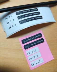
I’m pretty sure I’d have seen the black two-way terminal -stickers on somewhere else but can’t remember. Then again, I might be mistaking it for the similarily styled black BEOLINK sticker that can be seen on fe. BC9000’s back (no two-way IR there but I presume it hints to the device communications over the 7-pin DIN connectors and/or the MCL2 system).
Location: Helsinki - Finland
My B&O Icons:
Added now to the archive.org item: I scanned the single-page instruction sheet on where the dealer preparing the upgrade should stick the version stickers to, and most importantly the nice two-way terminal labels (to be placed on the BM and the box) 😎
Using a Dymo labelwriter, I printed myself new ones (as the NOS stickers had completely lost adhesion).
Location: Helsinki - Finland
My B&O Icons:
Thanks!
I have an older MCUMall GQ-4X USB Programmer, but any EPROM programmer that supports these older DIP-chips should be able to read the ROMs. It takes a bit of effort to get into the CPU box and to the ROM chip, but one could of course replace the battery or caps while there… wouldn’t hurt to replace those.
The seller I bought my BM4500 two-way kit also had an BM6500 kit for sale, but the single kit was already on the expensive side with shipping so I skipped getting them both.
On a related note there is currently a BM7000 ROM for sale on german eBay (https://www.ebay.com/itm/257132321336), but although the description says 1.3, the chip label says it’s 1.1. Someone probably upgraded and put the old chip in the bag and the seller didn’t notice.
Location: Helsinki - Finland
My B&O Icons:
Thanks!
With both BIN files you can write whichever version you want (two-way comms or the BM-as-link-room-mode only in 1.6, as you pointed out in Discord).
The chip in my unit (and the replacement) was a generic 27512 EPROM, which is still readily available. Mine was M27512FI, ie. by STMicroelectronics but any manufactorer should be fine (as long it’s the same 28-pin DIP package). I couldn’t find the speed rating for either chips, but in this case I’d guess the “slowest” 200ns part should work (elsewhere, like vintage computers the speed of the ROM might be important). You’ll also need an UV-eraser (for the old EPROMs with window on top) and an EPROM programmer. I’m sure there are also newer pin-compatible variants (EEPROMs, ie. no UV-erasing needed, or write-once chips if you just want to write a chip once and not re-use it).
I find it interesting that the BM4500 was shipped with the “limiting” software (if the 2-way IR hardware was fitted). Also the release notes telling a fix for “Beosystem 4500 may intermittently block and it is necessary to remove the mains plug” sounds pretty annoying bug, and surely would’ve caused calls to dealers! (I might have actually experienced this on my unit with the old ROM once or twice, I always thought it was just an effect of a low battery but apparently not!)
Location: Helsinki - Finland
My B&O Icons:
I looked at the ad and thought that they look really nice! Reminds me of the A8 headphones that I had. The leather carry-pouches are very nice too. I have absolutely no touch with the other brands if it’s a common thing but the case doubling as an audio transmitter sounds like a nice feature.
I was contemplating on the idea of “I might even like to buy those, as a celebration for the 100th anniversary” but now that I looked at the price; nope.
Location: Helsinki - Finland
My B&O Icons:
Location: Helsinki - Finland
My B&O Icons:
I’ve seen that in the MCL catalogs too.
That’s got to be a 3rd-party electrical box, B&O probably made only the foam inserts themselves 😁 I am not sure how many of these were really sold (I don’t think any of the 90’s B&O speakers were in any way water-proof?).
Not very practical either to be disconnecting the outdoor units if the temperature falls below 0° (as the instructions say!).
I like how they call the older rectangular MCL transceiver the “oblong” one 😀
Neat find anyway, I like these obscure accessories!
Location: Helsinki - Finland
My B&O Icons:
15 September 2025 at 15:12 in reply to: Was this really a thing? (Furniture options in 1990’s) #69692Interesting! The cover page has prices in GBP so perhaps this was some kind of a local thing by some single dealer with contacts? The catalog itself and the photos look very professional and the design (manual, not products) would’ve fooled me.
Location: Helsinki - Finland
My B&O Icons:
23 August 2025 at 19:29 in reply to: SOLVED !! Beomaster 7000 has suddenly become very silent #69056Anything on the headphone out?
Is the white dummy-plug present at the Beomaster’s LINE IN/OUT connector (below the speaker 1 connectors)?
Location: Helsinki - Finland
My B&O Icons:
-
AuthorPosts


