
Forum Replies Created
-
AuthorPosts
-
 BRONZE Member
Interesting you found TR11 to be malfunctioning, and replacement to be the solution. Thanks for sharing your findings @Dargo !
I currently have two BeoLab 8000’s with auto stand-by problems, both when using RCA/Line-in for audio input.
- Won’t switch on, always red Led. Although, the auto stand-by switching works well with PowerLink.
- When music stops, auto stand-by repeatedly switches Off > On > Off etc.
Could TR11 also be the cause for these two issues?
Location: The Netherlands
Favourite Product: BeoSound 9000
My B&O Icons:

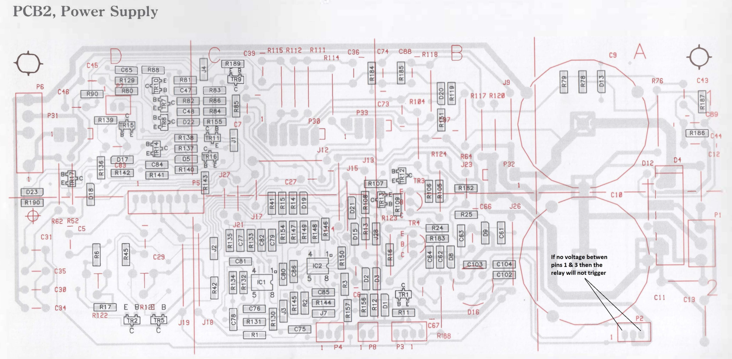
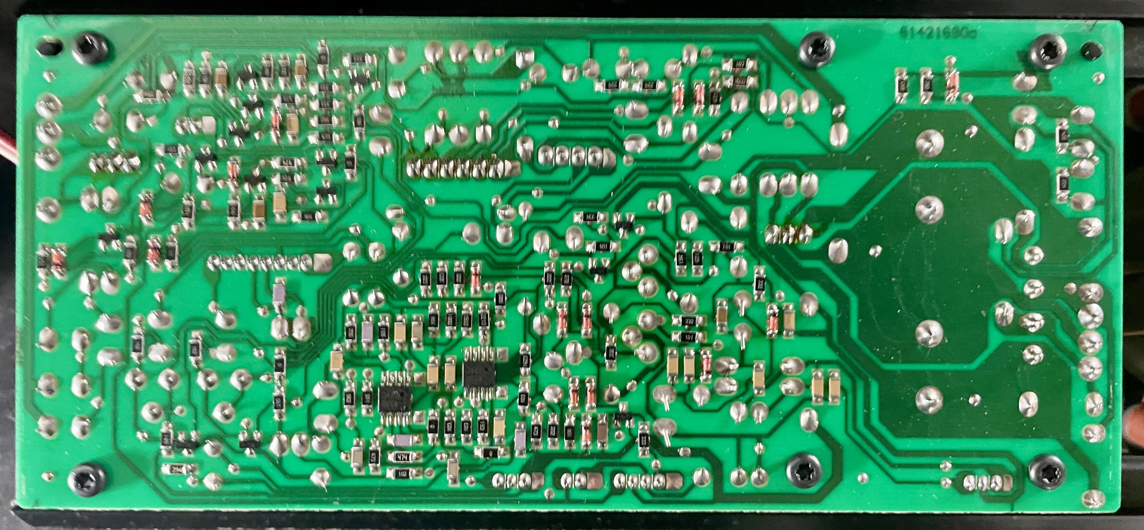
Today I tried starting the comparison measurements. As a reference / working speaker I wanted to use another BeoLab 8000 with serial 16xx xxxx. But I found out that the PCB layout of components is slightly different than the trouble BeoLab I am working on (13xx xxxx), and from the PCB02 drawing I have from the Service manual.
To show the difference: first the drawing of PCB02 I have from the Service Manual, and underneath a picture of PCB02 from the 16xx xxxx speaker I wanted to use for comparison.


IC1 is still clear, but I am not sure about the position of C75, R136, and TR16.
Question
- Could you help me find where these components are, or maybe you have a visual layout of this PCB02 version?
Location: The Netherlands
Favourite Product: BeoSound 9000
My B&O Icons:
Thanks again gentleman!
I will start to measure between the ‘bad’ and a good speaker next week. As you suggested Keith, between P2 pin 2 and the listed components.
I have a sin wave app on my phone which I will use as a continuous audio signal.
To be continued!
Location: The Netherlands
Favourite Product: BeoSound 9000
My B&O Icons:
Thanks again Keith! I hoped for a positive result with IC1, but I took into account that this would not be the trouble component. Nevertheless, we have come so far (at least in excluding trouble causes), so I will not give up.
Next step
Like you suggest, I will continue with continuity testing. To make sure I am looking at the right components to check …Question
Could you pleasde indicate to me, which components I should check, with the reference of the scheme (below) of the suspect area you posted before in this thread? (Take it as the way it takes the least time for you; either the components to check, or the ones I shouldn’t)
Location: The Netherlands
Favourite Product: BeoSound 9000
My B&O Icons:
Update after replacing IC1.
Before replacing IC1 with a new one, I checked R136 which I had removed a few steps back. It still measured 10K ohm, so I put it back to position.
Then I removed IC1 and replaced it with a new one.
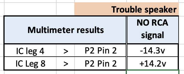
And of course I measured the voltage on leg 4 and 8: -14.3v and +14.2v. So exactly the same as with the old IC1.Just to be sure I also checked putting an audio source to the RCA/Line In; as expected, no switching on.
Question
- What would be the next step to check?
- If damaged copper traces (by foam rot) could still be a cause, in which part of the PCB do you expect those damages should be?
Location: The Netherlands
Favourite Product: BeoSound 9000
My B&O Icons:
Thnx Keith.
Swapping IC1 is on my list for tomorrow.
To be continued.
Location: The Netherlands
Favourite Product: BeoSound 9000
My B&O Icons:
Thanks for your patience with me Keith. I am still learning, but I get this one.
Here’s the new measurements with: the negative lead of the multimeter on Pin 2 of P2 for ground, and the positive lead to Leg 4 and Leg 8 of IC1.

Location: The Netherlands
Favourite Product: BeoSound 9000
My B&O Icons:
Thnx @Keith !
I just checked legs 4 & 8 of IC1 = +/- 28.8 volts
That’s quite different than the +/- 15 volts it should be …
Location: The Netherlands
Favourite Product: BeoSound 9000
My B&O Icons:
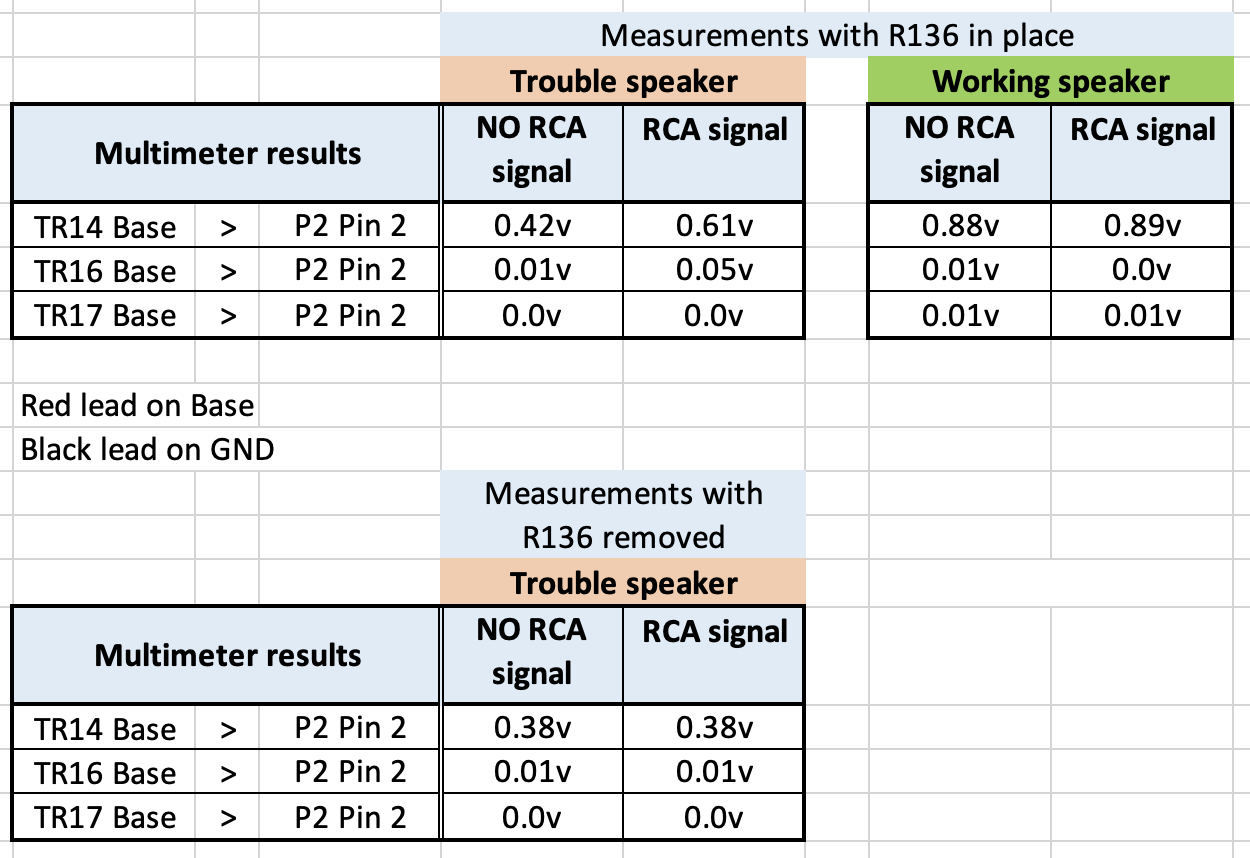
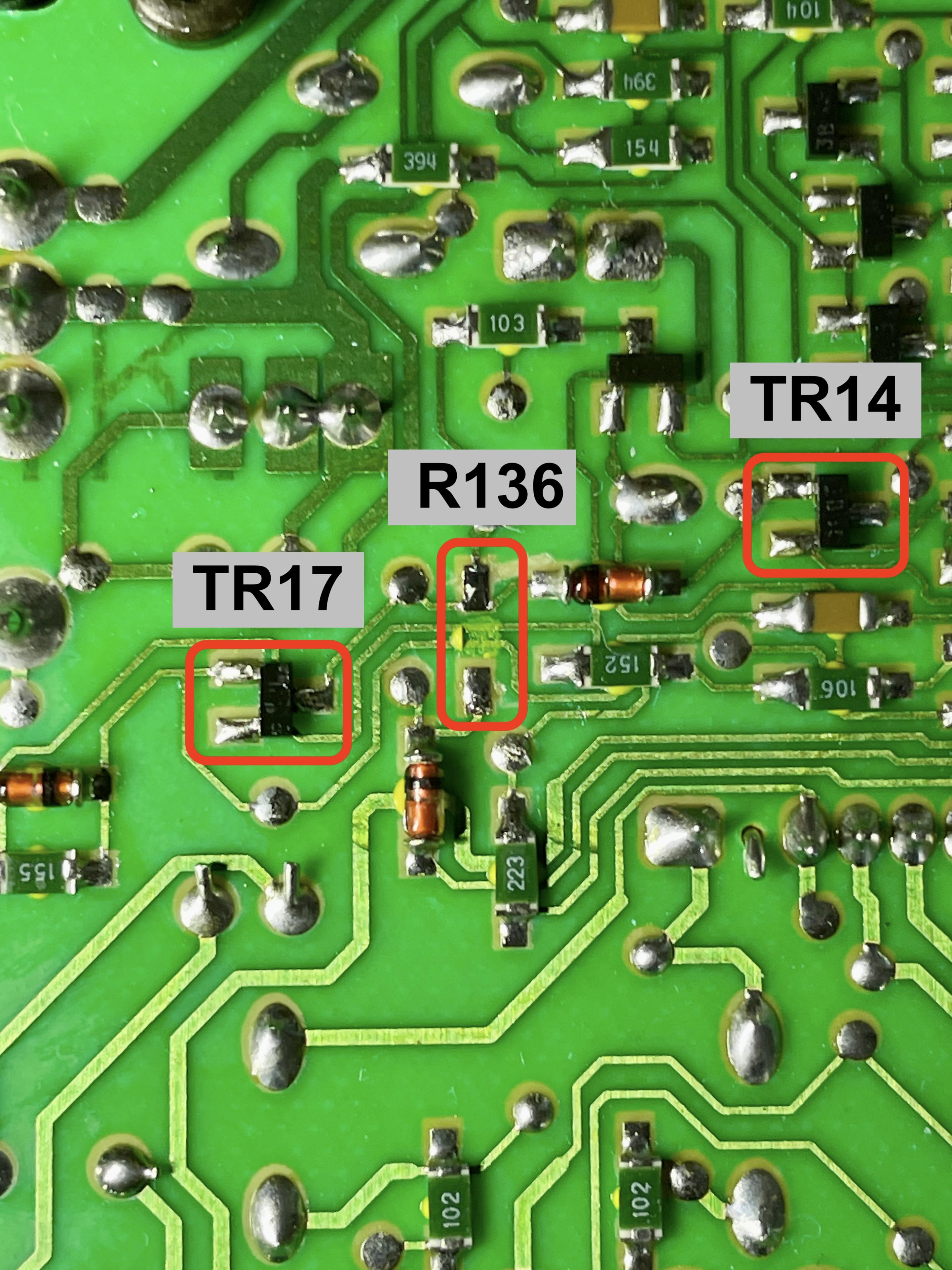
Here’s the results of measuring TR14 at Base, after removing R136.
Curious to learn what the results mean.
R136 removed.

Location: The Netherlands
Favourite Product: BeoSound 9000
My B&O Icons:
Thnx Keith, I will di that check and report it tomorrow.
Location: The Netherlands
Favourite Product: BeoSound 9000
My B&O Icons:
@Keith: thanks, I guess I misunderstood.
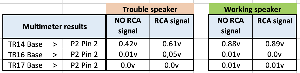
So I re-measured with the multimeter in DC voltage.
Also, I did the same measurement with a speaker that switches correctly on the RCA/Line-in.
This is what you meant?
Location: The Netherlands
Favourite Product: BeoSound 9000
My B&O Icons:
@Glitch: Thanks for your input and especially the visualization. This helps understand what to look for. So I will check again.
@Keith: Also thanks a lot!
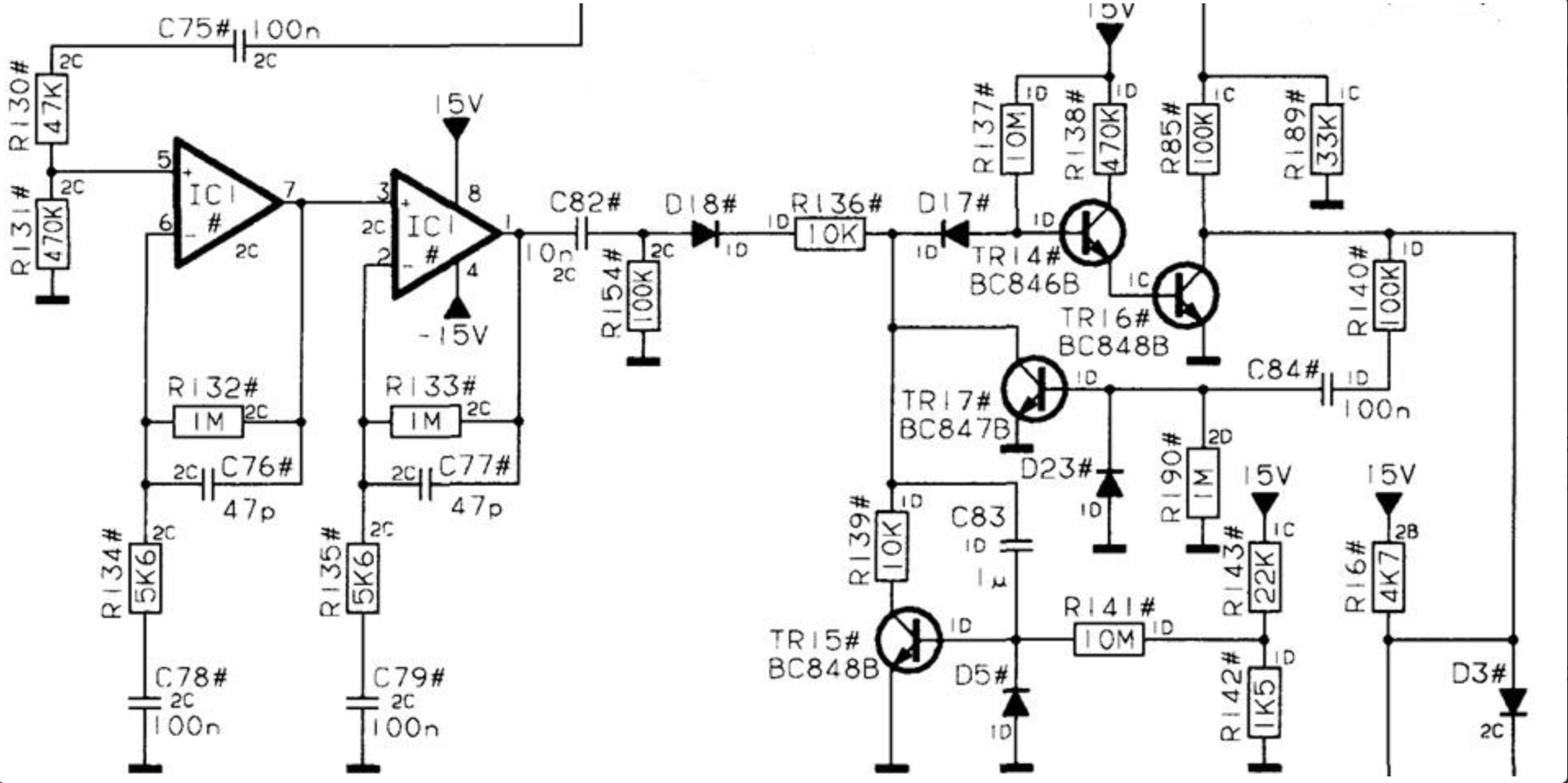
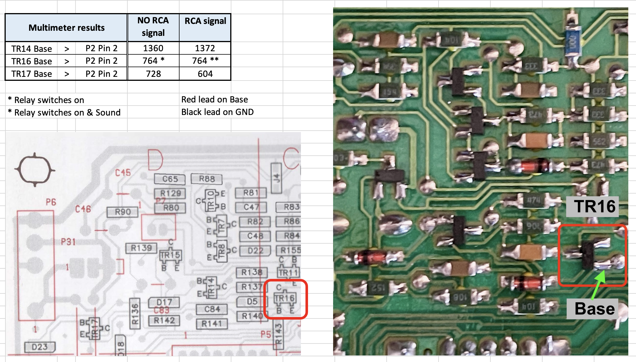
TR14, TR16 & TR17
In the meantime I measured what you suggested. Since I do not have an oscilloscope, I used a multimeter (Voltcraft VC130-1), in diode/continuity mode. IO found out that the direction of TR16 on my PCB is 90 degrees different than the layout in the Service Manual. But I assumed the Base to still be the left leg of the two next to each other.
You can see the results below. In all measurements, no continuity signal but a value measured.
Measuring at TR16 with & without signal on RCA, the relay switched on. With audio signal on the RCA, music was also there.Additional
In the schematics of PCB02, I read that IC1 should measure +15v at leg 8, and -15v at leg 4.
- I measured 29v.
As IC should also measure +15v at leg 8, and -15v at leg 4, I checked that one too.
- Also 29v.
Question:
- What does this mean to you?
- In the meantime I have also received a new IC1. Do you suggest to execute the replacement, or do you have another suggestion?

Location: The Netherlands
Favourite Product: BeoSound 9000
My B&O Icons:
In addition I did a test on the Input selector switch on PCB05, I measured all positions of the switch with a multimeter. And then did the same with a switch on a PCB05 from a working speaker. In comparison all results were the same.
I also swapped a PCB05 from a working system to this speaker. Results the same; in the RCA position the LED stays red.
To be continued when I received IC1.
In the meantime, still open to suggestions that help problem solving.Location: The Netherlands
Favourite Product: BeoSound 9000
My B&O Icons:
Me too.
Location: The Netherlands
Favourite Product: BeoSound 9000
My B&O Icons:
19 November 2024 at 15:15 in reply to: BeoLab 8000: P4 / 230v connector to PSU-PCB broken, replacement? #61048Thnx a lot @Glitch!
After checking the connector block close by, I could see the release tabs.
Pulling them a bitt outwards indeed enabled me to pull the wires and the internal terminals.After that I was able to reconnect the terminals better to the wire.
All fine now!Location: The Netherlands
Favourite Product: BeoSound 9000
My B&O Icons:
I think you’re right that AUX is just AUX.
And that the DIN AUX connector on the BS9000 only has pins 1 – 5.Location: The Netherlands
Favourite Product: BeoSound 9000
My B&O Icons:
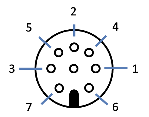
Though B&O uses an 8-pin DIN connector, for this purpose you can use a 5-pin DIN connector, using only 3 pins.
It is all about connecting a cable with 3 leads to the right pins, for getting the stereo signal from your WiiM in to the BS9000.
The 3 leads are: (picture show male DIN connector from the back/solder side, or female from the front side)
- Gnd to pin 2
- Right channel to pin 4
- Left channel to pin 1

Location: The Netherlands
Favourite Product: BeoSound 9000
My B&O Icons:
You can definitely make this work.
I am sure Steve from @soundsheavenly can help.
Can you jump in Steve?
Location: The Netherlands
Favourite Product: BeoSound 9000
My B&O Icons:
16 September 2024 at 13:17 in reply to: BeoLab 8000 woofer scratching noise: can it be solved? #59129Thnx @matador !
They way you describe it, sounds very much the same to how I experience this.
Cloud you please share the Spotify link to this song?
Please also mention at what point in the song (minutes:seconds) you experience the ‘vibration’.
Thnx in advance
Location: The Netherlands
Favourite Product: BeoSound 9000
My B&O Icons:
Hi Laurens. Here’s some things you can check.
(1) Check the Belt: Ensure the belt is in good condition and properly seated. A worn or loose belt can cause speed issues. If the belt is old, consider replacing it.
(2) Speed Adjustment: The Beogram 1203 has a speed adjustment mechanism. You might need to fine-tune this. Use a strobe disc to check the accuracy of the speed and adjust accordingly.
(3) Clean and Lubricate the Speed Change Mechanism: Sometimes, old lubrication can cause the speed change mechanism to stick. Clean out the old lubrication and re-lubricate with a suitable oil, like sewing machine oil1.
(4) Check the Motor Pulley: Make sure the motor pulley is clean and free of any debris. Sometimes, dirt or grime can affect the speed.
(5) Inspect the Electronics: If the mechanical parts are all in good condition, the issue might be electronic. Check for any faulty capacitors or resistors that might need replacing.There’s also a video on Youtube about fixing a slow 1203. I gaven’t fully watched it. But maybe you find something helpful.
Location: The Netherlands
Favourite Product: BeoSound 9000
My B&O Icons:
-
AuthorPosts