Forum Replies Created
-
AuthorPosts
-
 MadskpGOLD Member
Based on the HDD acces error and the age of the sytem it might be likely that the HDD has failed.
The Servicemanual indicates that the HDD can not just be swapped, but might have to be transferred and/or setup by the use of the B&O service tool which to my knowledge is not available for other that dealers and servicecenters.
Location: Denmark
MadskpGOLD MemberHave you tried testmode 27?
If I read the servicemanual correctly this should among other things tell if the HDD has an error (page 4.8 in the servicemanual)
Location: Denmark
MadskpGOLD MemberI had some time today to do a little testing.I tried different option settings on both the BC9300 and the BS Ouverture (opt. 0, 1 and 2) and on the BL3500 (opt. 5 and 6), but no difference in behaviour.In the proposed settting the Video ML/ Video non ML is missing. Maybe this is the cause of the behaviour.
Note: I have a Beosystem 7000 – T1611 – BLC connected in my Netlink. I have to set the BLC up as VMaster to work correctly if I’m rightI the tried to connect my Beocenter 6-23 to the setup, and now it works as expected and I can start a CD on the BC9300 (or the Overture when that is the master), join the Beloab 3500 with a single touch on the mute button and unjoin by another press ont the mute button. Also I can make a long press on the mute button and it will turn off the Master system.
So it seems that a video master has some effect on how the system reacts to link room commands regardless of the use of a 1611 converter or a real ML audio system (Overture in this case).
I will also try this with my Beocenter 2 to see if that also applies to a more modern ML audio system.
Location: Denmark
MadskpGOLD MemberI also had a little time yesterday where I tried to connect the White/blue and the pink wire i a ML cable and tried it withe the BS Ouverture + Beolab 3500 combo again with no difference in behaviour.
I have a RJ45->ML connection to my wall mounted BL3500, so I guess I also had this connection already.
Will try som othe combinations when time allows it
Location: Denmark
MadskpGOLD MemberDo you have the short circuit in your setups, @madskp? No idea if this is actually relevant or not.
I am not sure. Most of my stuff is in a non permanent setup, so I often switch cables between different units. I will try to check up on this when I have some time, probably in a couple of days.
Normal in ML : short STBY will stop only the product in the room addressed. Long STBY will put the whole system in standby.
That is also what the manuals for the link products describe, so even more puzzling that I can reproduce this issue with two different Audio Masters.
Will also try to look into trying with other components if the above does not change anything.
Location: Denmark
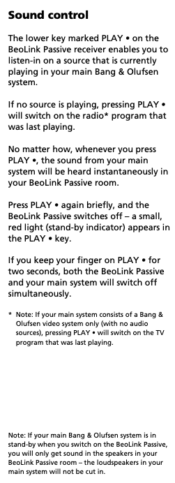
MadskpGOLD MemberInteresting enough that it seems to work when converted to MCL.
But according to the user manuals for at least the Active, Passive and BL3500 it should work as the MCL did:
From the BL3500 user manual

Location: Denmark
MadskpGOLD MemberSo I just did some testing with some of my equipment:
Beocenter 9300 – 7 pin datalink cable – 1611 – masterlink cable – Beolab 3500 MK1 both with, and without a powerlink cable between the BC9300 and the 1611.
Beosound Ouverture – Masterlink cable – Beolab 3500 MK1
In bot cases I get the same behaviour as you describe even when I start the music from the master system.
Now what I expected. I will see if I have time to look more into this today
Location: Denmark
MadskpGOLD MemberJust some extra notes to be clear:
Do you start the music from the main system or from one of the link rooms, and do you also have the speakers in the main room in use in these scenarios?
I belive if the music is started from a link room the behaviour is correct as long as the main room is not in play.
I will see if I can verify this on one of my systems today.
Location: Denmark
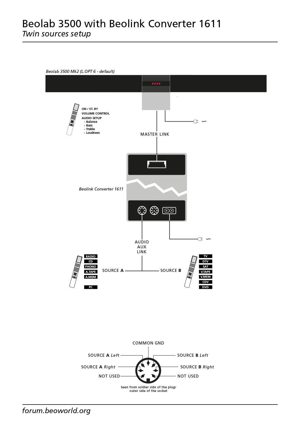
MadskpGOLD MemberTo explain your observations about the 1611 it csn work as a stand alone audio and video masterthus allowing for two selectable sources on any ML link room product. This was tested very throughly in another thread which among other things resulted in this great sketch made by Matador https://beoworld.org/wp-content/uploads/beoworld_images/24903/fpsantcr1nreqhki1h7n4w2zt2x2471h.jpg
Location: Denmark
MadskpGOLD MemberJust a few more inputs based on your post.urrently running it without. 1611 is connected to the Aux port on the BM6500, it doesn’t seem to work at all in Tape which would have been my preference.
The datalink86 bus that is needed for connection to the 1611 is only available in the AUX connector.
try the Active at the same time as the Passive, possibly with the BL2000 too, all connected through my RJ45 distributor. If I have sufficient bits of cable.
What about the active have you tried if that works the same as the passive?get the BM33oo out of the shed and try that connected to the 1611. Not sure if this will work but if it does with the same behaviour it would suggest it’s my 1611 that’s the problem
The BM3300 does not have datalink86, so is not able to work with the 1611.
Also if the Beolab 2000 works fine in the setup the 1611 should be OK.
maybe try with the BL3500 via ML, though this might be more destruction than I have time and space for.
Maybe just try to disconnect the MCL part of the system (remember to turn it all of before you do so), just to rule out if that has any effect on it. MCL shares the same datalink bus as the datalink 86 in the AUX conecetor of the BM6500, so there is a possibility that something could disturb each other
Let us know how your testing goes. Maybe that can make for new inputs to the mystery
Location: Denmark
MadskpGOLD MemberNice project to look into. I have e few inputs to your Powerlink thoughtsI’m also not sure how “overload” is implemented, so there’s some research required there.
Not sure it was ever used in many powerlink speakers. Looking at the schematics for Beolab Penta and Beolab 3000/5000 it seems that pin 8 is not conencted to anything other than the two DIN connectors in the speakers.
and it looks like I’ll snatch L&R output as well.
But is that volume regulated?
Location: Denmark
MadskpGOLD MemberThank you Guy and Madskp for your input and links.
Where can I download and purchase Linkplayer 1 and Linkplayer 2 please? I have searched and cannot find this.You can not purchase it anymore. The deveopment of thissoftware ended over 10 years ago and i belive the developer dropped the project and moved on with other things
Location: Denmark
MadskpGOLD MemberI think it depends on how the individual cables are shielded.
If you can fin the Beolink Handbook (available for paying members on Beoworld In the Biotech section) you can see the cable drawings with pinouts. For the RJ45 Powerlink cables the wire collars are the same as n a network cable, so I will assume it can be used. I did use I Believe CAT6A network cables to make some short RJ45 to 8 Pin DIN adapters at some point, and they work fine. But might be different for longer cable runs.
Location: Denmark
MadskpGOLD MemberThis does sound weird. according to the user manual this should only happen when you do a long press:
Only other place I have found mention of shut-in the whole system of with a single press is in and older manual for the MCL system where you could make a solder connection inside it to get that behaviour. I have not seen mention of this for the ML system components.Have you tried to power up the devices in different order to see if that affects the behaviour? Or do you maybe have an other IR eye you could try with?Location: Denmark
MadskpGOLD MemberRegarding BM-Link. The official website for the project is this http://www.odlund.se/bmlink/download.html
Newest release was developed for OS X 10.6 Snow Leopard, so might be hit and miss how much newer version it will work on.
I do not think that either the official Beoport software or BM link will show metadata. There was another project called Link player that maybe did show some metadata on some systems, but you might have to research that further searching on the archived forums. I believe there are threads about it on both of the two archived forums.
Linkplayer was, I believe developed as a paid software, so you would need a license key to make it work today, and that might also only work on older version of Mac OS.
For both BM-Link and Linkplayer they are using iTunes as the internal player on the Mac.
Location: Denmark
MadskpGOLD MemberCongrats, really nice project! Well done!
Hey great to see you here on Beoworld again 🙂 try to take a look at TK’s threads about datalink, maybe something there you can chime in on.
General failures on the BS5/BM5 has been, to the best of my knowledge the HDDs and the motherboard. None of which that are reused. So hopefully this can revive a few dead units.
Motherboards indeed. On my BM5 there was no life in the motherboard whenI aquired it, so I replaced it with another of the same type. The issue is probably due to bad capacitors on the VIA Epia EX motherbaord. I have yet to try to recap the original board to see if that will bring it to life again.
Location: Denmark
MadskpGOLD MemberThanks for the extra info. This just got on my todo list for when I have some of the other projects I am working on finished
Location: Denmark
MadskpGOLD MemberVery impressive project, look very interesting.
If I understand it correctly the Beosound 5C will works as a controller for Sonos devices? That could be very useful for me as I have Sonos devices in the house, but am missing an alternative to a phone/tablet for controlling the Sonos devices.
If it also works with the Beo4 remote control to play/pause, skip tracks and change volume for the Sonos devices that is even better 🙂
Is it correct to assume that this will also work with the Beoport if the display is powered separately and the IR is connected to the Beoports IR in port?
Location: Denmark
MadskpGOLD MemberFinally fixed the CD skipping on my Beosound 2300, and I’m embarrassed to say it was simpler than I thought: dried or non-existant grease on the transport rails. Drove me crazy because the skip happened at a very certain point on a CD, down to the second each time. So I thought it was a scratch in the CD — but a new copy of that same CD skipped in nearly the same place. Obviously it was that particular area of the rail that was either blocked by gunk or too dry.
Oh well, I got a CDM12 controller board re-cap out of it… (and all these SMD’s seen below tested within spec after removal, of course! 🙂
Great you got it working, and great info for other owners. I might try to go back to my Ouverture that need’s two CD presses before starting. Maybe the rails can have somthing to say in this ( I have cleaned and relubricated the gears).
Location: Denmark
MadskpGOLD MemberHello and congrats on your Beolab 2500 Speakers.
The speakers were part of Beosound set. Speakers came with two power cables and two 5 pin powerlink cables. Are those the right cables? Can I use them?
So just to be sure to not mess up please advise me if I l am thinking right about connecting them to MX4000.
Powerlink from speaker into power link on TV (left+right). Speaker independently into power outlet. PL on TV on.
This should be the correct way to do it yes. Powerlink cables are often 8 Pin, but the extra pins are not needed for the Beolab 2500 speakers (my own Beolab 2500 also have 5 Pin connectors on the cables).
Any other settings on TV? Will the built in speaker also remain working?
According to the user manual you will get a new menu called speaker in the sound menu when you connect powerlink speakers. There you should be able to select 1 for internal speakers, 2 for external speakers and 3 for both internal and external speakers.
Hope this will get you some extra sound for your gaming
Location: Denmark
-
AuthorPosts
