Forum Replies Created
-
AuthorPosts
-
 MadskpGOLD Member
You might wan’t to consider how to control the BC2.
For the connection types you are mentioning yourself you might need to first activate an input on the contour and the operate the BC2 either on it’s front panel or with the Beoremote one in IR mode (I have no experience with Beoremote One myself, so unsure about how the switching between bluetooth and IR works). This might be a little clunky user experience to operate.
A more user friendly approach might be to get a Beolink Converter NL/ML which can make the sources from the BC2 visible as sources for the Contour.
Not sure if operation of the DVD part can be done this way, but judging by your post it sound like a nice to have option.
Note that auto update does no longer work on the Beolink converters NL/ML, so if it does not have the latest software version you might need to get it updated by a B&O dealer to get full functionality.
Location: Denmark
MadskpGOLD MemberNo experience in this kind of machinery other than my father had one we ocasionaly tried out when I was a kid.
However my memory told me that there was a thread about repair of these in the old forums, so her is a link to that thread. Hope it might be helpfull https://archivedforum2.beoworld.org/forums/t/18355.aspx?PageIndex=1
Location: Denmark
MadskpGOLD MemberTry to look at page 14 here https://bangolufsenassistentgohe.blob.core.windows.net/manuals/APPS_AND_ACCESSORIES/BEOREMOTE_ONE/EN_1405_BeoRemoteOne_Online_Guide.pdf
that should explain how it is done with a Beoremote One
Location: Denmark
MadskpGOLD Memberwhich option settings would I need to set? Can I use a BeoRemote One IR for it?
If you arguing house the BC2 and the BL3500 in the same room the BC2 should be set to option 0 (no IR) to avoid double commands. If it has been used in a setup where the speakers were connected to a Beovision it might allready be in that option. You can try if you can activate it with a CD command.
The BL3500 should be in option 6 provided you do not have any B&O TV in the same room. If it has been previously been used in a linkroom it is probably allready set to that.
Having never used a Beoremote one I can’t tell you how it is done on that.
Location: Denmark
MadskpGOLD MemberThat should work provided the correct option settings have been use previously.
Location: Denmark
MadskpGOLD Memberanybody who nows what the readings ( volts ) should be. maybe the microcomputer pcb 3
is faulty.
I have tried to open one of my passives and did some measurements to compare.
One important thing to note.The button on the front is not and on/off button but an off button. If I activate the passive from a B&O musicsystem via Powerlink I can press the button and turn the Passive off, but I cannot turn it on again with the button. On the front of mine it is also named OFF.
that is the problem , with only 220v connecet , it is on , the power up is high on p200 pin 8 , and when i connect 5v to
pin 1 on powerlink scoket , p200 pin 8 goes lowThis is also how mine reacts, so this should be normal behavior, and also how I think it should work based on the schematic.
p200 pin 1 is connecet to on/off switch when i press it it goes low and when
i relece it it goes high .it looks as it is the oppesit as it should be.The same reaction I see on mine. Also note my comment regarding the button function.
Location: Denmark
MadskpGOLD MemberJust a few cents from me. I have a set of Beolab 4 sepakers and have an accespoint placed relativly close to one of them. If the distance between the accespoint and the speaker is to short (<5cm or so) the Speaker is beginning to make ticking noises. So these speakers are prone to some interference from other things. Btw. I am using original MK3 Powerlink cables (the thin ones).
Location: Denmark
MadskpGOLD MemberAnd just to round this up I have also replaced the three capacitors mentioned in Beolovers blogpost https://beolover.blogspot.com/2021/06/beogram-cd50-typical-restoration-steps.html?m=1 which has also been a great reference in regards to replacing the belt.
Last thing to check is the datalin control which I tested by connecting it to my Ouverture
 And it is working just great with full control 😀
Location: Denmark
5 June 2025 at 18:33 in reply to: Controlling a Beomaster 6500 via the TV/Aux Datalink’86 pin #66211MadskpGOLD Memberhat said, it may only be possible to have maximum control via the BM8000 IR input. In this instance, the Powerlink cable from the 1611 would go to an Arduino which in turn sent the control signals through an IR emitter, and the line audio output (or input) went through Tape2. From what little I know about the BM8000, I’ve read that the TP2 jack is fully functional, apart from Datalknk
That makes sense. It is the same way B&O themselves did it with the MCL Beolab kit that would allow the Beomaster 8000 to be used with MCL82 link room equipment. A. little more on that in this thread if you are interested https://forum.beoworld.org/forums/topic/pile-of-mcl-equipment/#post-62596
That said the need for link rooms with a BM8000 may be down to very few people if any 😉
Location: Denmark
MadskpGOLD MemberAs for the NL/ML converter settings. If you set it up as a Audio Master you can choose to distribute the Core sources to ML Audio source names like CD, A.MEM, Radio, N.Radio, or N.music or what ever is easiest to control with the Beoremote one.
Also this can give an extra local input if needed.
The extra input form a Beolink converter 1611 I mentioned before can then be activated with any video command like, TV, DTV, DVD etc.
As for the the Beolab 3500 there can be a few settings that needs to be adjusted depending on how it has been used before. If it has been used in a link room on a ML network before you probably should be good to go without changing any settings.
Location: Denmark
MadskpGOLD MemberSince you have no audio or video master on your masterlink side, you need a master link power box. B&O part # 8052447.
You can read more about it on pg 29 of the BeoLink Handbook http://beointegration.com/uploaded/EN-BeoLink-handbook-v1-7.pdf
Alternativly you can use a Beolink converter type 1611. That will also supply the needed power and might even be cheaper and more available. Also this can give an extra local input if needed.
Location: Denmark
MadskpGOLD MemberHve you tried to measure the voltage where you have noted “on”. There should only be voltage there if a Powerlink cable is connected and activated from at Beosystem
Location: Denmark
3 June 2025 at 08:52 in reply to: Controlling a Beomaster 6500 via the TV/Aux Datalink’86 pin #66154MadskpGOLD MemberOne takeaway to note is that with a little effort, it appears to be entirely possible to make a cheap translation dongle which allows any vintage B&O component to interface with any other vintage B&O component (something one or two people have already worked on). So one could, for example, easily make a dongle which would allow a Beomaster 5000 or BM8000 to work with more modern datalink protocols that the 5500-7000 know how to translate.
Do you mean the Datalink 86 protocol so it would be possible to connect to more modern link system (for example Masterlink via 1611 converter)?
Location: Denmark
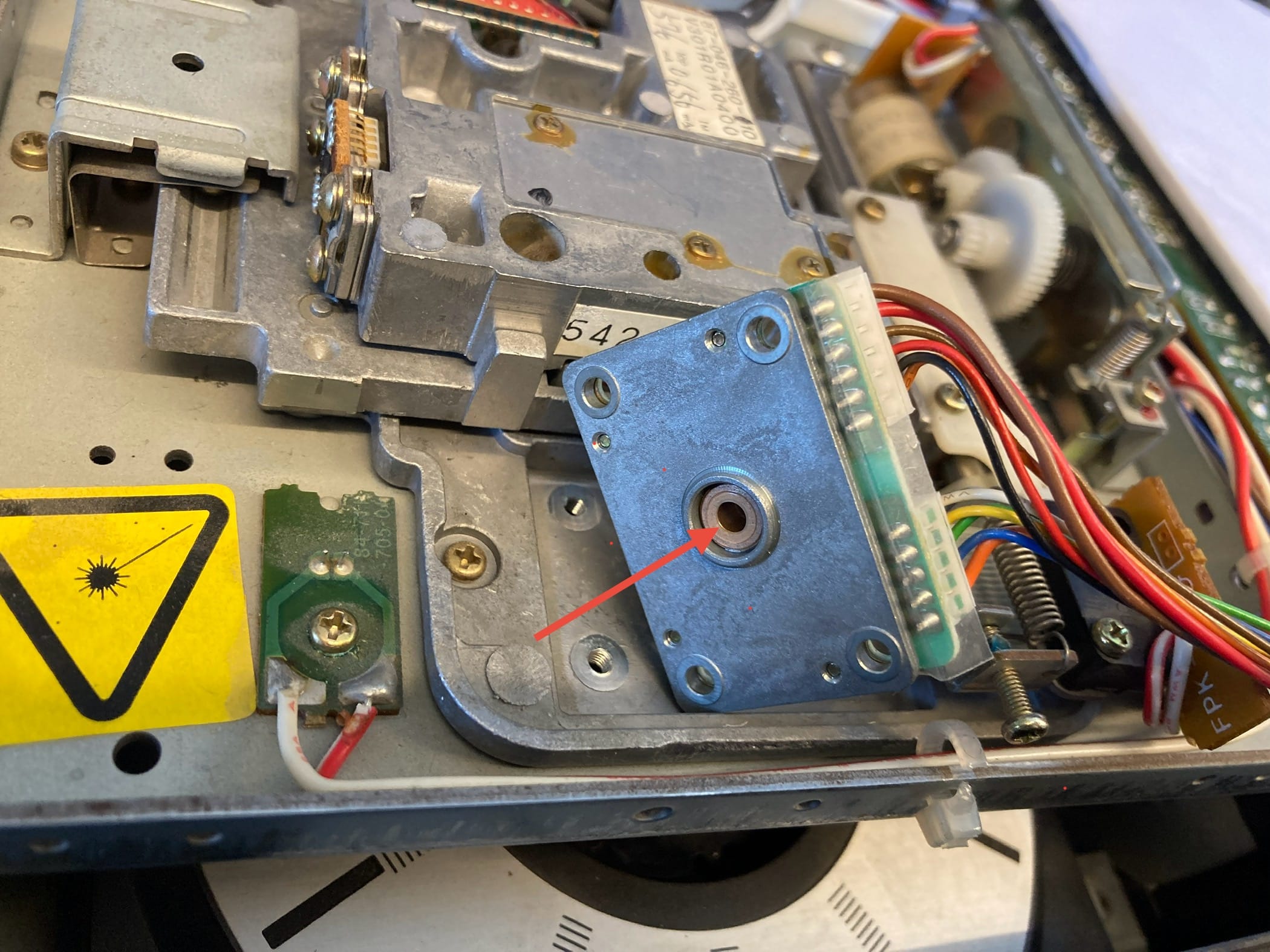
MadskpGOLD MemberBe sure to measure the distance between the spindle and the metal plate above before unscrewing it. I have noted a lot of comments in other threads that the distance shown in the service manual is not correct, so better to make it the same as it was.
Location: Denmark
MadskpGOLD Member1.3mm allen key worked for me
Location: Denmark
MadskpGOLD MemberI decided to fix the spindle motor and for now it looks like a succes for me
I did a writeup in my other thread about it https://forum.beoworld.org/forums/topic/boegram-cd50-carrige-slow/#post-66138
Location: Denmark
MadskpGOLD MemberHad some issues with CD’s not playing or starting 1-2 minutes into track 1.
Reading in this older thread https://archivedforum2.beoworld.org/forums/t/628.aspx?PageIndex=1
It is mentioned that this could be due to the spindle motor not being able to get up to high enough rpm to read the start of the first track which is placed in the inner part of a CD.
It seems like a few people in that thread had luck disassembeling the spindlemotor cleaning and relubricating it.
After trying a few other things I decided to do the same. It was actually easier for me than I thought it would be based on the description in that old thread.
I guess it is down to applying enough force on the motor PCB and pressing the shaft against som metal.
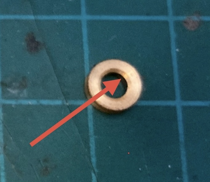
Be aware as mentioned in that old thread that the brass ring that comes of has a chamfered edge that has to point against the motor
The spacers mentioned in the other thread did not fall of on mine so I let them be where the were and concentrated on cleaning and relubricating the shaft and bearing
Pressing the brass ring on the shaft again was actually harder for me than getting it of. It is easily pressed to much against the bearing making the motor hard to spin. I found that placing a guitar plector between the motor housing bell and the PCB when pressing the brass ring on gave just the right amount of clearance.Aftewards it was just placing the CD spindle in the same distance as before disassembely and the reassemble the CD mechanism.All in all I used maybe half an hour on this.The result: Every CD I have tried no starts at 0.00 on track 1. Of course I have to long term test it, but I allready think this was worth it 😀Next up the non responsive Beocord 5000 to keep the CD50 companyLocation: Denmark
MadskpGOLD MemberSecondly, I was wondering if modern, non-B&O, speakers can be connected to it and how I would go about doing that if so? Also do I need passive speakers or will active ones work as well?
Both passive and active speakers will work. For the passive speakers you will need some 2 pin DIN speaker plugs. You can connect any active speakers with analoginput to the Powerlink connection on the BM7000. You will need an adapter from the 8 pin DIN (as not all pin is needed it can also be a 5 pin din) to either RCA or minijack depending on what the active speaker you connect has for input. Try to look at at the site sponsor Sounds Heavenly webshop. he will have the right adapter for this.
Location: Denmark
1 June 2025 at 06:48 in reply to: Which POWERLINK output of Beomaster 6500 to use to connect to an external amp #66069MadskpGOLD MemberI understand your confussion looking at the manual where the connected active speakers are named left and right. I gues that drawing is just to show how to connect two B&O active speakers with two separete regular powerlink cables. Selection of which speaker is left and which is right is done on the B&O active speaker
Therefor that setup would also be possible with a Powerlink Y connector only one of the Powerlink connectors on the Beomaster as alle pins in these 2 are internally connected toghther
Hope this helps understand the Powerlink connections
Location: Denmark
31 May 2025 at 18:56 in reply to: Which POWERLINK output of Beomaster 6500 to use to connect to an external amp #66054MadskpGOLD MemberTo answer the first question, powerlink has both left and right signals in the same connector. Therefore the adapter type with one DIN connector will work fine.
As for quality differences between the two adapters I am not the right one to tell.
Location: Denmark
-
AuthorPosts