Forum Replies Created
-
AuthorPosts
-
1 March 2025 at 11:04 in reply to: BeoSound 9000: Torx screw in glass-door hinge stuck ? > SOLVED #64234
 BRONZE Member
Thanks @B&O Orlando
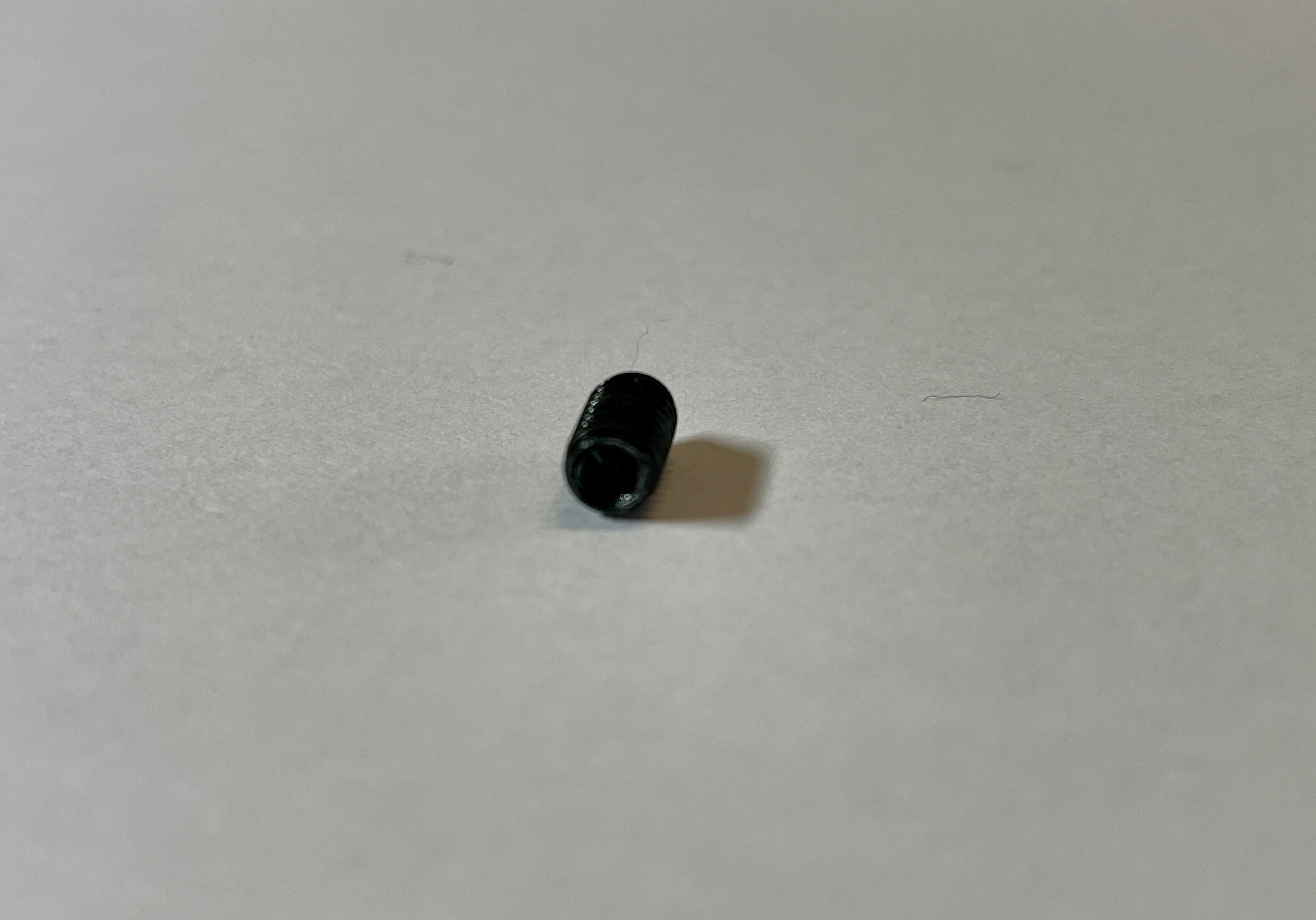
I think you are right about the color. I took another look and compared the Torx screws from both hinges. The right/upper one (the losse one) is certainly black, and the left/lower one looks grey. So like you said, probably not original.


I have let the ‘WD-40 anti corrosion lock lubricant’ do its work overnight, but unfortunately still no movement.
Hopefully I can get a Torx-8 screw driver with a T-handgrip, to get a bit more force. But like you said, it is tricky.
QuestionIf this doesn’t work, I might have to drill the Torx-screw out, but then also replace the hinge (part) in which it sits.
But:- Is this a possibility?
- Is the hinge part available?
- About the CD Laser Pickup: the Service Manual mentions ‘CD VAM 1250 from serial no. 15143261’. So this means I need a VAM 1250 for this BeoSound 9000 MK3?
Location: The Netherlands
Favourite Product: BeoSound 9000
My B&O Icons:
 22 February 2025 at 13:56 in reply to: Line-In on ML devices – using ML Gateway and NL/ML Converter #63925
But that is possibly because the ML connector on the BeoLab 3500 has to be activated by the Beo remote, to pick up the audio signal.
Location: The Netherlands
Favourite Product: BeoSound 9000
My B&O Icons:
22 February 2025 at 12:39 in reply to: Line-In on ML devices – using ML Gateway and NL/ML Converter #63923Hi Frog,
I am not sure if I understand your question correctly. But if you want to stream with a Chromecast through a BeoLab 3500, it is possible.
If this is what you want … I do this via the DIN-connector and a Mini-Jack-to-DIN cable. In this case you need a cable that connects the right way to the pins in the DIN-connector.
Then you have to use the Beo remote to activate the ML on the BeoLab 3500, and streaming works.
Let me know, if this is what you meant.
Location: The Netherlands
Favourite Product: BeoSound 9000
My B&O Icons:
Thanks again!
Location: The Netherlands
Favourite Product: BeoSound 9000
My B&O Icons:
SOLVED
I must admit, I had real doubts about this issue, whether they would be caused by dirty glass door sensors or glass. Especially since the CD-sledge showed a hick-up when trying to move from position q1 to any other CD position. Therefor I was thinking about some mechanical disruption in the movement area of the CD-sledge.
Nevertheless, I decided to once more do a thorough cleaning of the 2 prisms, the whole aluminum surface area, and the glass door (inside & outside). After that I ran TM71 in the Service Mode …. And yes, the ‘Cleaning Required’ notification has gone, and all movements of the CD-sledge are back to normal. Also no more hick ups when the CD-sledge starts moving from position 1 to any other CD position.
So my lesson here, cleaning has to be thorough cleaning!
@Severed_hand_of_skywalker: thanks for your advice. It did do the trick.Location: The Netherlands
Favourite Product: BeoSound 9000
My B&O Icons:
17 February 2025 at 17:20 in reply to: BeoLab 8000: Broken plastic leg supporting PCB > which glue ? #63854Thanks @Jaspers1996
I have a 3D printer, so having a 3D model would be my preference.
Location: The Netherlands
Favourite Product: BeoSound 9000
My B&O Icons:
Thanks for your reply and advice. I have done so. In fact, I have even done some more cleaning by carefully using compressed air. Also near the CD-sledge.
Unfortunately , there was no effect. I still see the ‘Cleaning Required’ notification in the display.
Reading the Service Manual and the possible test modes, I decided to do TM71: Mechanical test of ‘Finger Protection’, sledge and led. I have CD’s loaded in positions 6, 5, 4, 3, 2 but no CD in position 1. Here’s what happens (looking at each step of this test):
- Glass door opens = Correct.
- Glass door closes = Correct.
- Sledge moves slowly to CD6 = Not Correct.
- Display shows: Cleaning Required > CD1 > Load CD.
In this step, the sledge moves about 2mm down from position 1 (like in normal use), but then doesn’t do anything.
So here the test ends/does not continue for all other steps. (All others are listed underneath)Question:
- What is wrong, and what next step should I make?
Remaining steps of TM71, not executed:
- Sledge moves Quickly to CD1 =
- Sledge moves Quickly to CD6 =
- Glass door opens =
- Sledge moves Slowly to CD1 =
- Sledge moves Slowly to CD5 =
- Sledge moves Slowly to CD1 =
- Sledge moves Slowly to CD4 =
- Sledge moves Slowly to CD1 =
- Sledge moves Slowly to CD3 =
- Sledge moves Slowly to CD1 =
- Sledge moves Slowly to CD2 =
- Sledge moves Slowly to CD1 =
- Test finalizes in position 1, with the glass door still open.
Location: The Netherlands
Favourite Product: BeoSound 9000
My B&O Icons:
I just looked back in my logs. I found:
- 1477 xxx with the old foam
- 1486 xxx with the new foam
So probably it changed somewhere between them.
Location: The Netherlands
Favourite Product: BeoSound 9000
My B&O Icons:
Congratulations, great this solves your issue!
BeoLab MK II does not have the ‘foam rot’ issue. BeoLab MK II is serial number 1699 2475 and up.
BeoLab MK I ‘younger’ serial numbers also have the newer (white) foam. I am not sure from which serial number onwards B&O started using the newer foam. But I think they started somewhere 16xx xxxx.
Location: The Netherlands
Favourite Product: BeoSound 9000
My B&O Icons:
You are welcome Nicolaas!
We kunnen dit ook in het Nederlands voortzetten, but for the B&O community we’ll continue in English.Isopropyl: yes, if you have the 96% alcohol from the pharmacy, it will do. For some parts of the cleaning I dip earths in the alcohol to rub the foam dirt away. For the surface of PCB’s (printplaten) ~I dip a small (soft) toothbrush in the alcohol and gently brush the PCB.
Yes, this type of damage on the copper traces can already cause the malfunction.
If you experience bad contact of the RCA connector, I would check this:
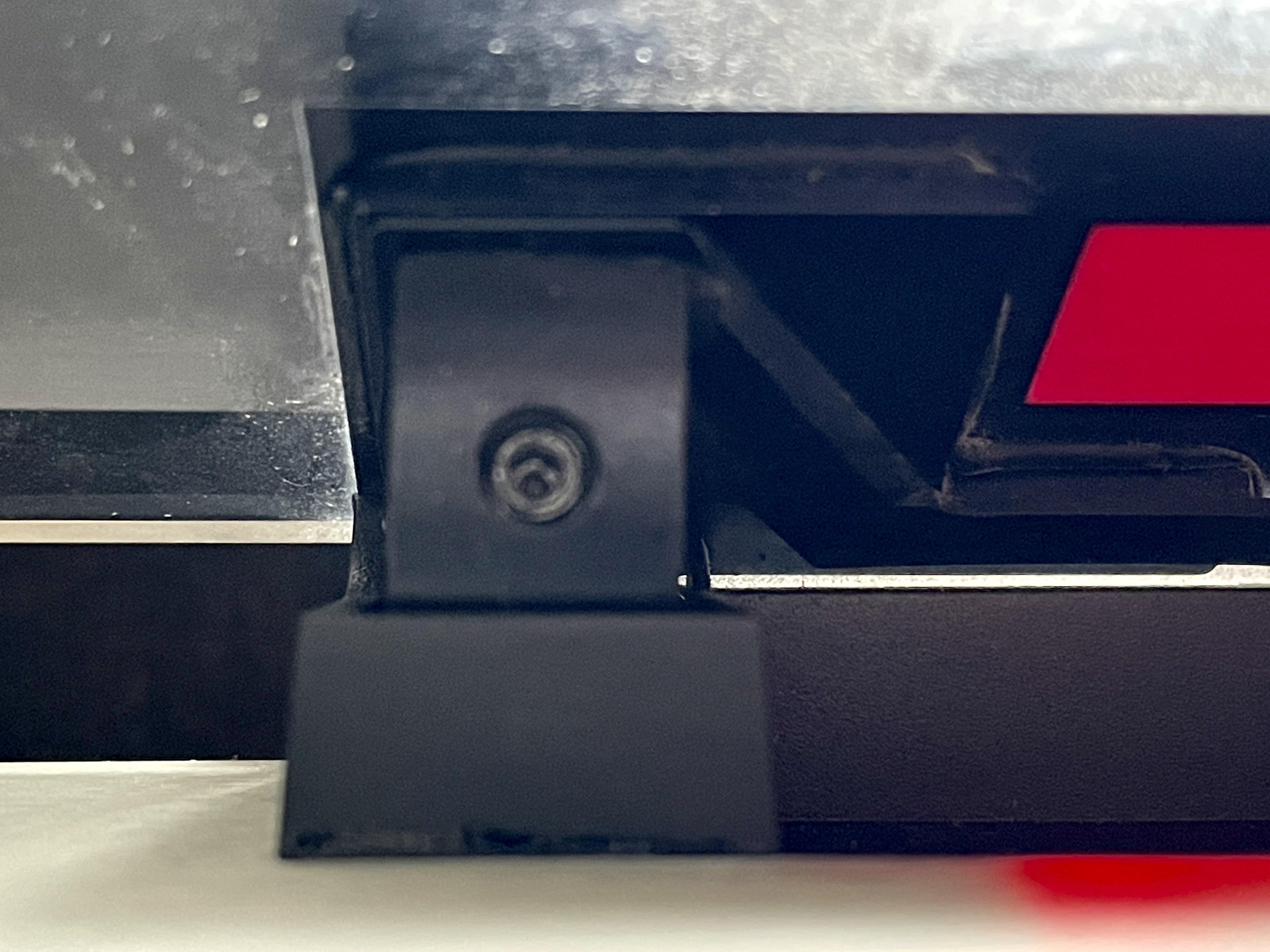
- The RCA connector has a flat nut on the bottom side of PCB05 (see picture). You will have to remove the cone cover on the top/point of the foot to get access. If you get there, check if the nut is still tight.
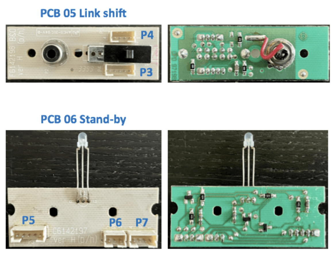
- What I have also seen, is that the foam dirt was sitting on PCB06 (see picture). This PCB connects PCB05 and all electronics inside the alu casing. It therefore also influences the auto stand-by function. So check if this one is dirty too and clean it if necessary.

BeoLab Penta; yes they are great!
Location: The Netherlands
Favourite Product: BeoSound 9000
My B&O Icons:
Hi Nicolaas,
Good that you post here and share what you have already seen.
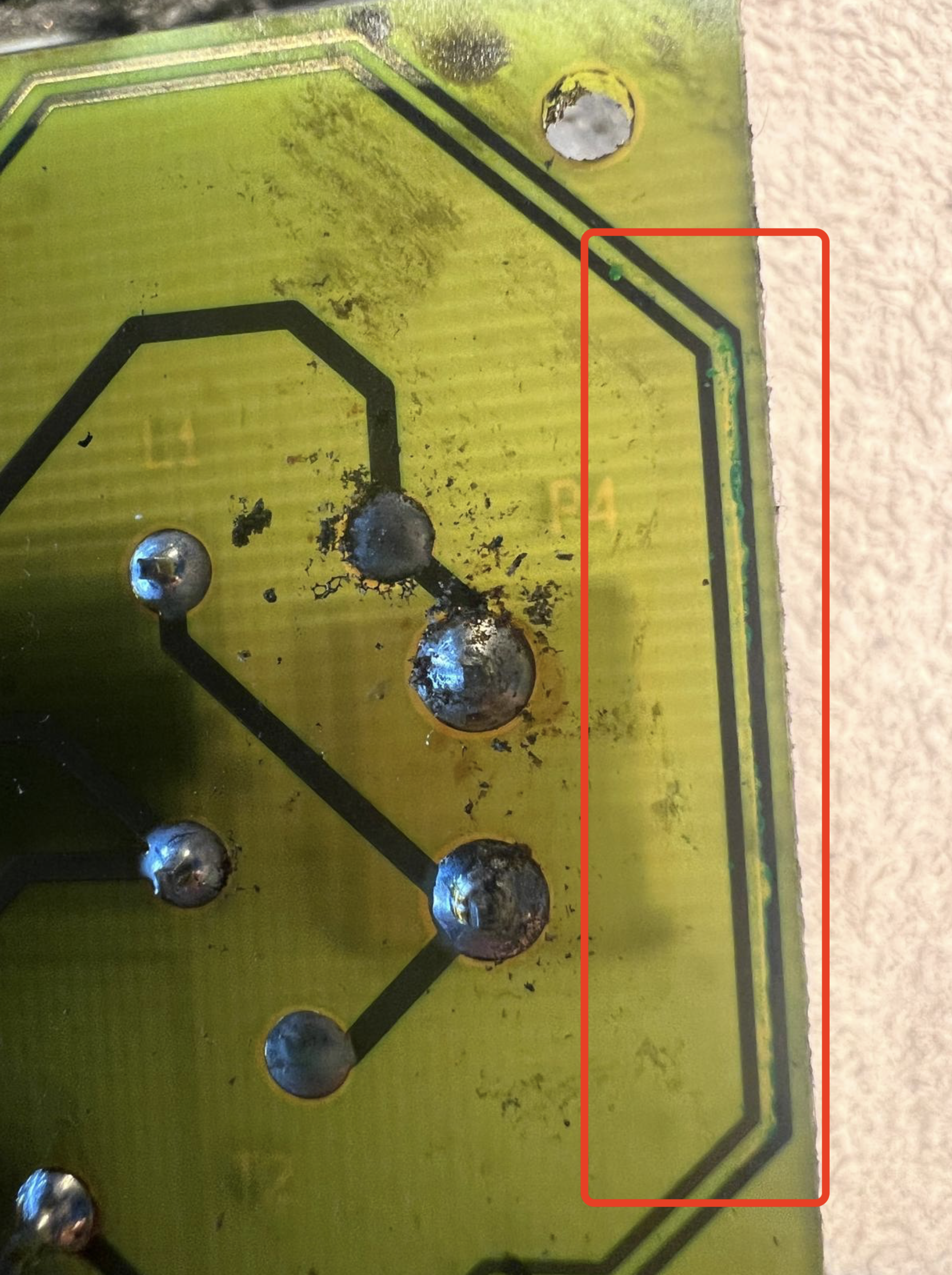
As I can see from your picture, the deteriorated foam has definitely done ‘its work’. Especially on the right side of your picture, one can see that the two copper tracks have been damaged. The foam ‘eats’ the tracks away (like bite marks in the traces), and this in many cases causes the Auto stand-by to not be activated or to switch back and forth continuously.

Here’s my suggestion
I t could be there are also other problems, but I would start with this.
- Remove the Amplifier & Power Supply panel from the alu casing. Do the same with the speaker panel. Be careful. The speaker panel has one cable and connector connected to the amplifier side. And the Amplifier/Power Supply has three cable connectors that connect to the botttom of the alu casing.
- Remove all the foam particles from all places where you see them. This can be a time consuming work, because it can be everywhere. Make sure you clean it away from PCB’s, connectors, components, … You can use isopropyl alcohol to get the sticky parts away.
- When done, create a bypass as shown in the picture underneath.

When this is all done, put all parts back in the alu casing and reconnect. Power up the BeoLab, put an audio signal to the PL or RCA input and check if the auto stand-by turns on.
Let us know the outcome.
By the way, are you Dutch?Location: The Netherlands
Favourite Product: BeoSound 9000
My B&O Icons:
Interesting you found TR11 to be malfunctioning, and replacement to be the solution. Thanks for sharing your findings @Dargo !
I currently have two BeoLab 8000’s with auto stand-by problems, both when using RCA/Line-in for audio input.
- Won’t switch on, always red Led. Although, the auto stand-by switching works well with PowerLink.
- When music stops, auto stand-by repeatedly switches Off > On > Off etc.
Could TR11 also be the cause for these two issues?
Location: The Netherlands
Favourite Product: BeoSound 9000
My B&O Icons:
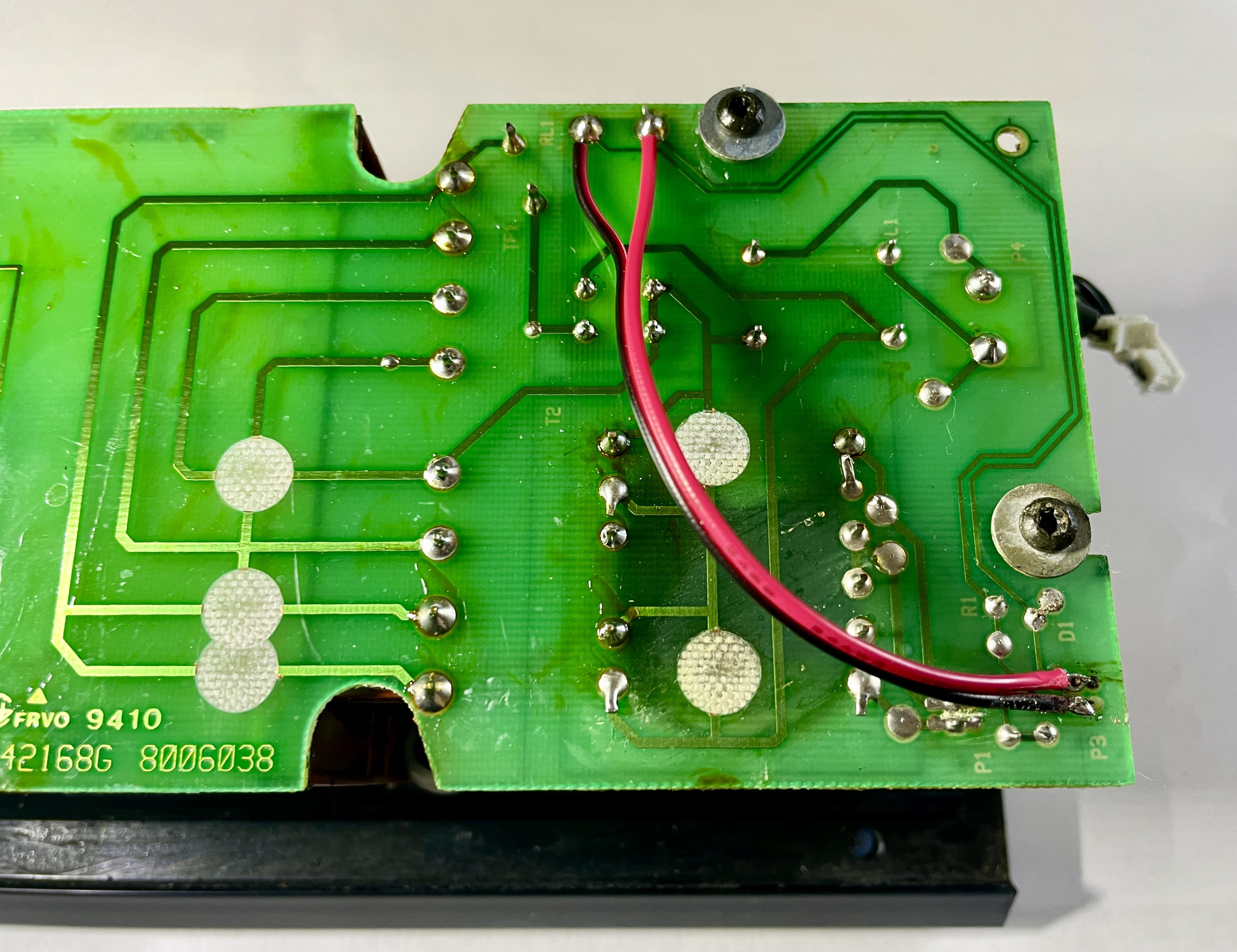
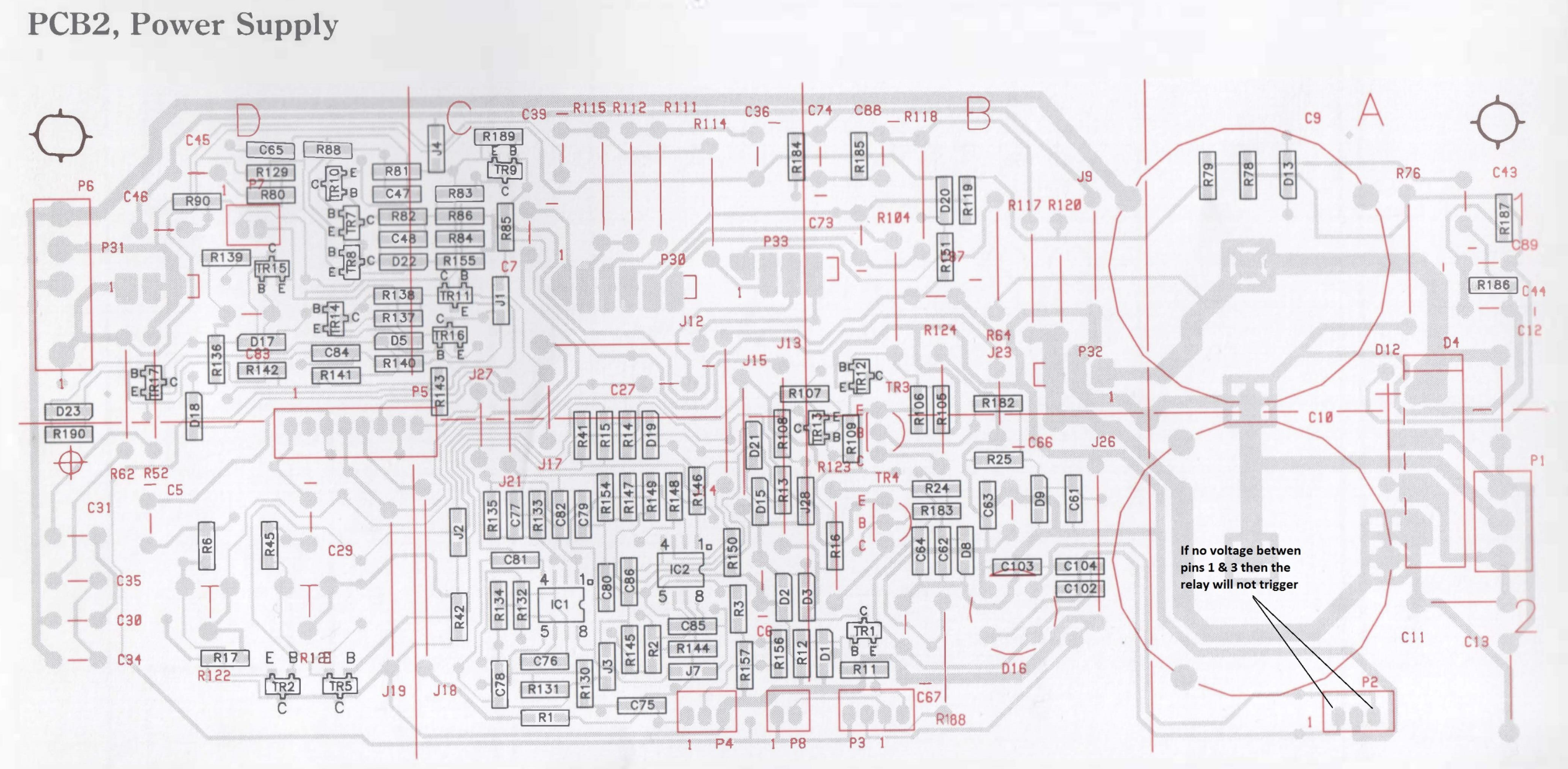
Today I tried starting the comparison measurements. As a reference / working speaker I wanted to use another BeoLab 8000 with serial 16xx xxxx. But I found out that the PCB layout of components is slightly different than the trouble BeoLab I am working on (13xx xxxx), and from the PCB02 drawing I have from the Service manual.
To show the difference: first the drawing of PCB02 I have from the Service Manual, and underneath a picture of PCB02 from the 16xx xxxx speaker I wanted to use for comparison.


IC1 is still clear, but I am not sure about the position of C75, R136, and TR16.
Question
- Could you help me find where these components are, or maybe you have a visual layout of this PCB02 version?
Location: The Netherlands
Favourite Product: BeoSound 9000
My B&O Icons:
Thanks again gentleman!
I will start to measure between the ‘bad’ and a good speaker next week. As you suggested Keith, between P2 pin 2 and the listed components.
I have a sin wave app on my phone which I will use as a continuous audio signal.
To be continued!
Location: The Netherlands
Favourite Product: BeoSound 9000
My B&O Icons:
Thanks again Keith! I hoped for a positive result with IC1, but I took into account that this would not be the trouble component. Nevertheless, we have come so far (at least in excluding trouble causes), so I will not give up.
Next step
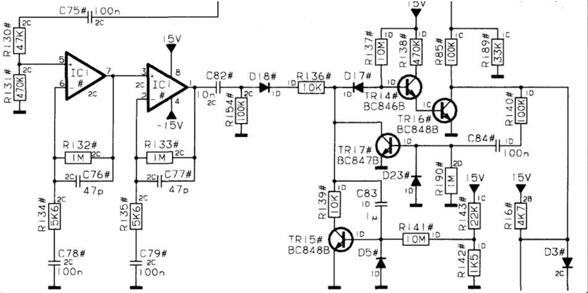
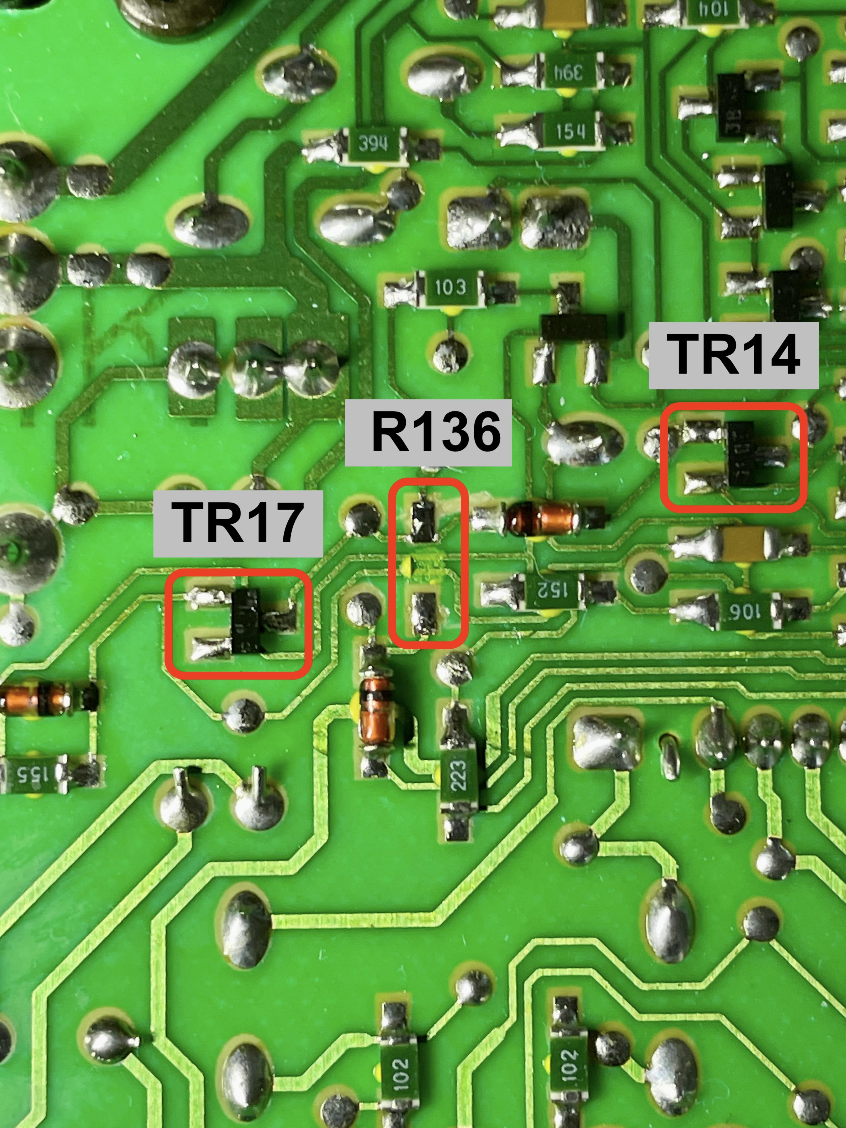
Like you suggest, I will continue with continuity testing. To make sure I am looking at the right components to check …Question
Could you pleasde indicate to me, which components I should check, with the reference of the scheme (below) of the suspect area you posted before in this thread? (Take it as the way it takes the least time for you; either the components to check, or the ones I shouldn’t)
Location: The Netherlands
Favourite Product: BeoSound 9000
My B&O Icons:
Update after replacing IC1.
Before replacing IC1 with a new one, I checked R136 which I had removed a few steps back. It still measured 10K ohm, so I put it back to position.
Then I removed IC1 and replaced it with a new one.
And of course I measured the voltage on leg 4 and 8: -14.3v and +14.2v. So exactly the same as with the old IC1.Just to be sure I also checked putting an audio source to the RCA/Line In; as expected, no switching on.
Question
- What would be the next step to check?
- If damaged copper traces (by foam rot) could still be a cause, in which part of the PCB do you expect those damages should be?
Location: The Netherlands
Favourite Product: BeoSound 9000
My B&O Icons:
Thnx Keith.
Swapping IC1 is on my list for tomorrow.
To be continued.
Location: The Netherlands
Favourite Product: BeoSound 9000
My B&O Icons:
Thanks for your patience with me Keith. I am still learning, but I get this one.
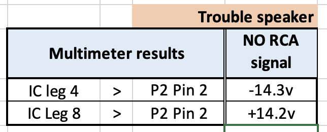
Here’s the new measurements with: the negative lead of the multimeter on Pin 2 of P2 for ground, and the positive lead to Leg 4 and Leg 8 of IC1.

Location: The Netherlands
Favourite Product: BeoSound 9000
My B&O Icons:
Thnx @Keith !
I just checked legs 4 & 8 of IC1 = +/- 28.8 volts
That’s quite different than the +/- 15 volts it should be …
Location: The Netherlands
Favourite Product: BeoSound 9000
My B&O Icons:
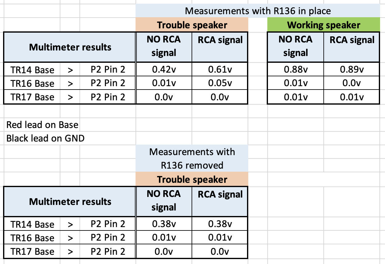
Here’s the results of measuring TR14 at Base, after removing R136.
Curious to learn what the results mean.
R136 removed.

Location: The Netherlands
Favourite Product: BeoSound 9000
My B&O Icons:
-
AuthorPosts