Forum Replies Created
-
AuthorPosts
-
 hcraig244SILVER Member
left the deoxit to dry off and had another go…switches all operate much better, tried FM works fine both channels….so does the phono input, got it on test or the day see how it performs, the suspect broken track will need some attention/investigation for sure…nothing is getting hot right now…..so Dillen can I have a capacitor kit please? it’s easier for me to buy from you that trawl the component websites ;¬)
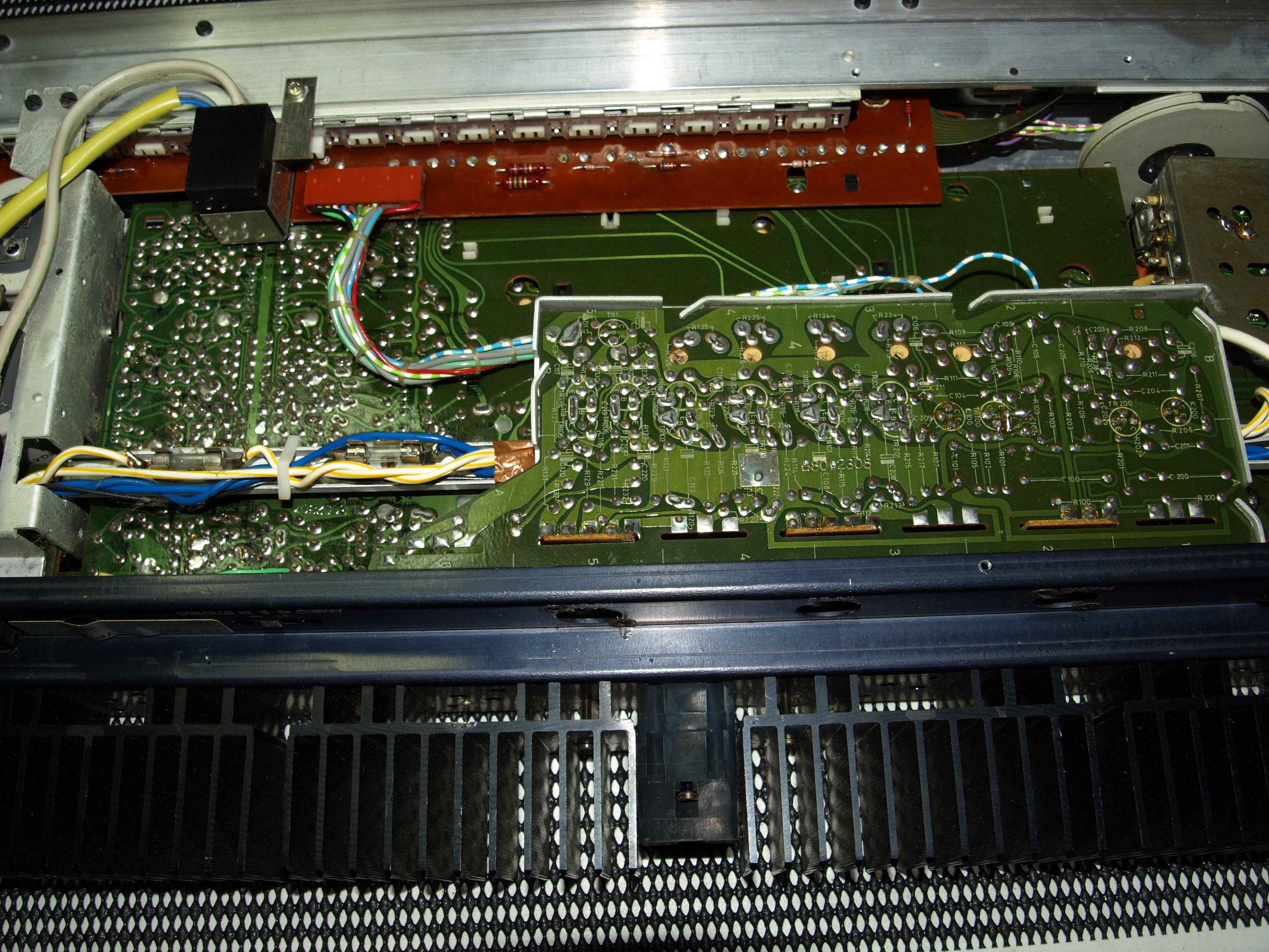
hcraig244SILVER Memberdusted away most o the debis and gave all the switches a blow over with de oxit and left them to soak…..did spot this….looks like a broken track
 hcraig244SILVER Member
underside look pretty clean however
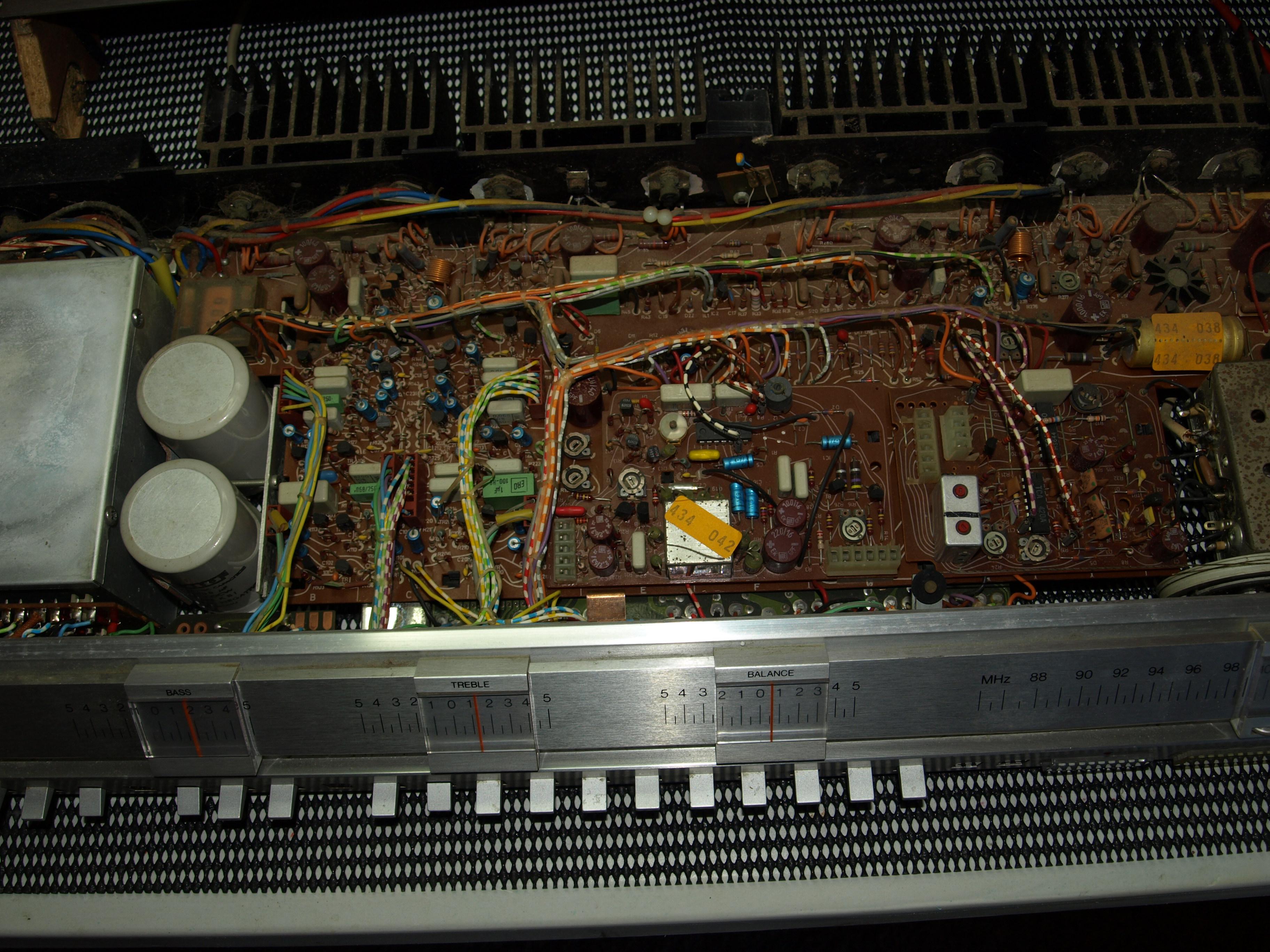
hcraig244SILVER Membercobwebs everywhere…..
hcraig244SILVER MemberA look inside gives a clue to its woes…..
hcraig244SILVER MemberGot to hand it to him….I have taken two of these apart in the past and they are an ordeal….still got one that works but it took a similar amout of effort to get it there…and considerably more time 😉
hcraig244SILVER MemberEnd of an era……….thanks to all who have made this site possible down the years and lets look forward to enjoying if for years to come
Craig
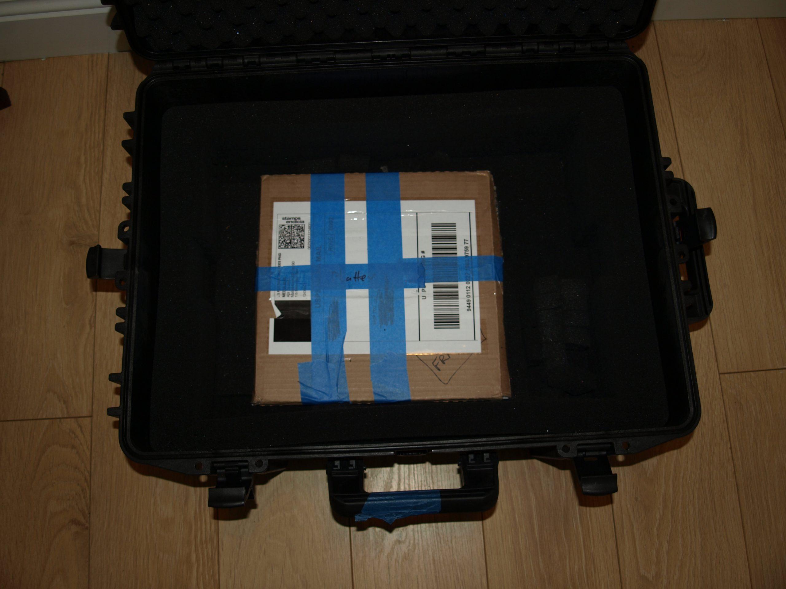
hcraig244SILVER MemberCouple of things to consider…….import duty, cost of delivery and possible damage during shipping…..
Craig
hcraig244SILVER Memberhcraig244SILVER MemberWhen you say you can manually operate the solenoid armature by hand and the tone arm drops, release the tone arm manually and the tone arm rises this is normal operation and suggests that mechanically all is well….also when you press start the tone arm moves to the drop point, assuming a disc is on the turntable, and stops ….but you hear a “click” this suggests that the solenoid is actually pulling in….is that the case? can you watch and see what happens when you hear the “click”
Craig
hcraig244SILVER MemberOk
Just had a look at my BM6000 units, I have two of them…….both do the same thing. When i power up from the switch at the back I cant actually hear the standby relay energising/clicking……the red lamp is illuminated. Pressing standby puts power to the tuning strength meter and also to the control position indicators, all function switches operate as normal…FM switch lights tuning indicator slider. pressing the standby switch gives an audible click as the relay de energises and all lamps go off except the red standby lamp….pressing standby switch again gives an audible click as the relay energises and power is restored……
dont know if this helps
hcraig244SILVER MemberA big thank you Lee and Keith…..I’m really not sure how long I have been a member of the site….I do know I have learned a huge amount from being a part of it, the advice and contributions from the legends of the site, in particular Dillen….have grown my knowledge exponentially, loved every adventure I have been lucky enough to be part of…….
Craig
hcraig244SILVER MemberBear in mind that the Commander uses ultrasonic not infrared…….have a listen and see if you can hear the standby relay operating when you first switch the mains power on……I have had issues in the past with a standby relay which although was operating its contacts where not making/breaking. The standby relay allows power to all functions however if your amp has been unused for a long time some of the lamps may have failed despite power being available, so may give a false impression that nothing is getting power…
hcraig244SILVER MemberHi Henrik..
Pretty much like yourself. the clock is ticking as some say…but overall I’m still in good shape for an old man ;¬)
Bert…could be your 6000 is stuck in standby, very difficult to diagnose without eyes on, and if yours are failing it wouldnt be easy for you to open her up and do some tests…but do replace the remote battery and give that a go…maybe someone closer to you will weigh in and volunteer some assistance, the UK is a long way to send such a heavy amplifier ;¬)
Craig
hcraig244SILVER Memberhehe…..sorry Henrik, my fault….how are doing anyway? all good……..
Craig
hcraig244SILVER Memberthese amps are certainly worthy of repair/restoration, they are a marvel of engineering…I believe hendrik from the site here lives on your part of the world, he has provided me with bits and pieces for 6000 quads in the past, he may be the one to help you….Im in the UK so not a lot of help I’m afraid
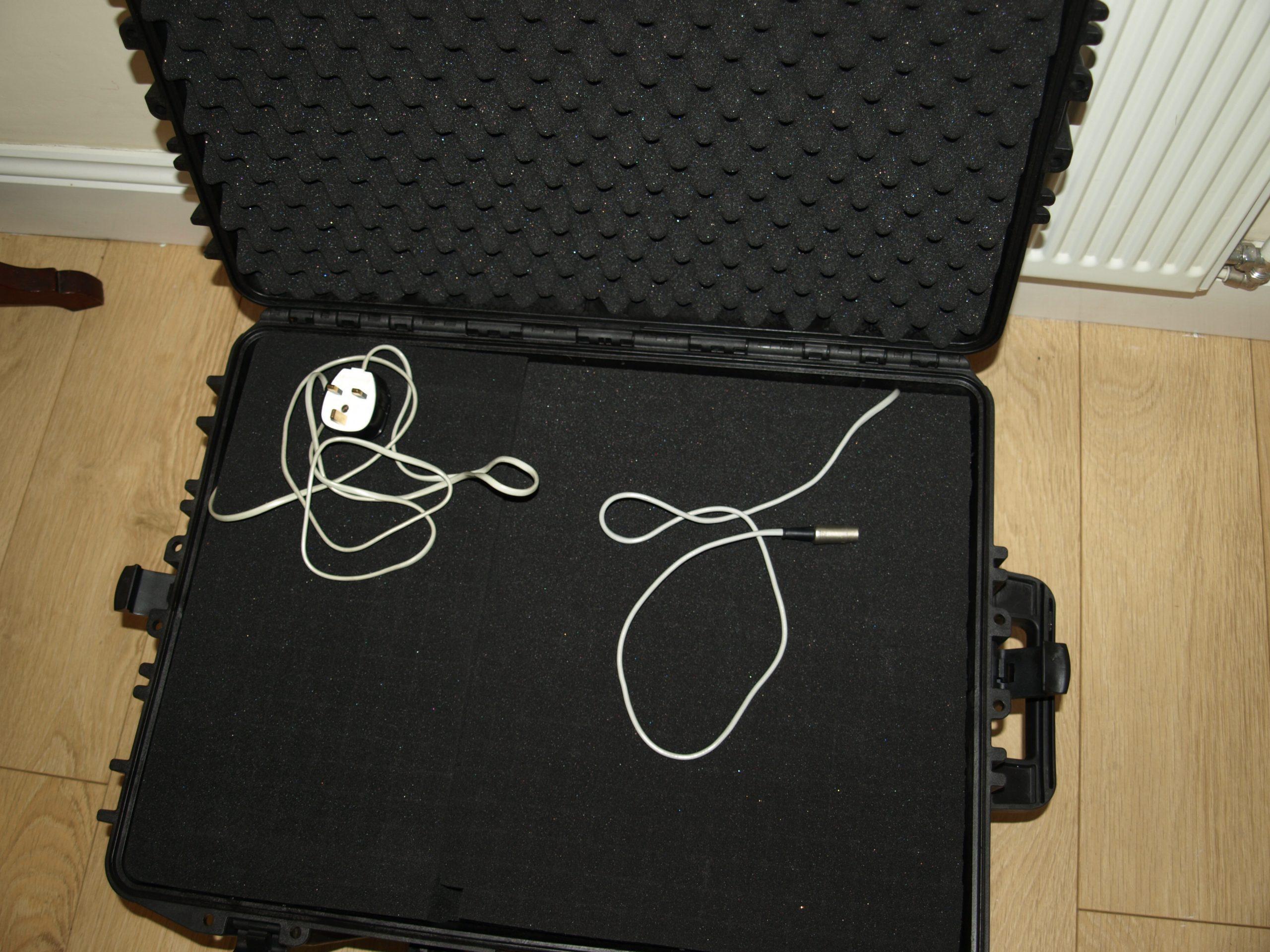
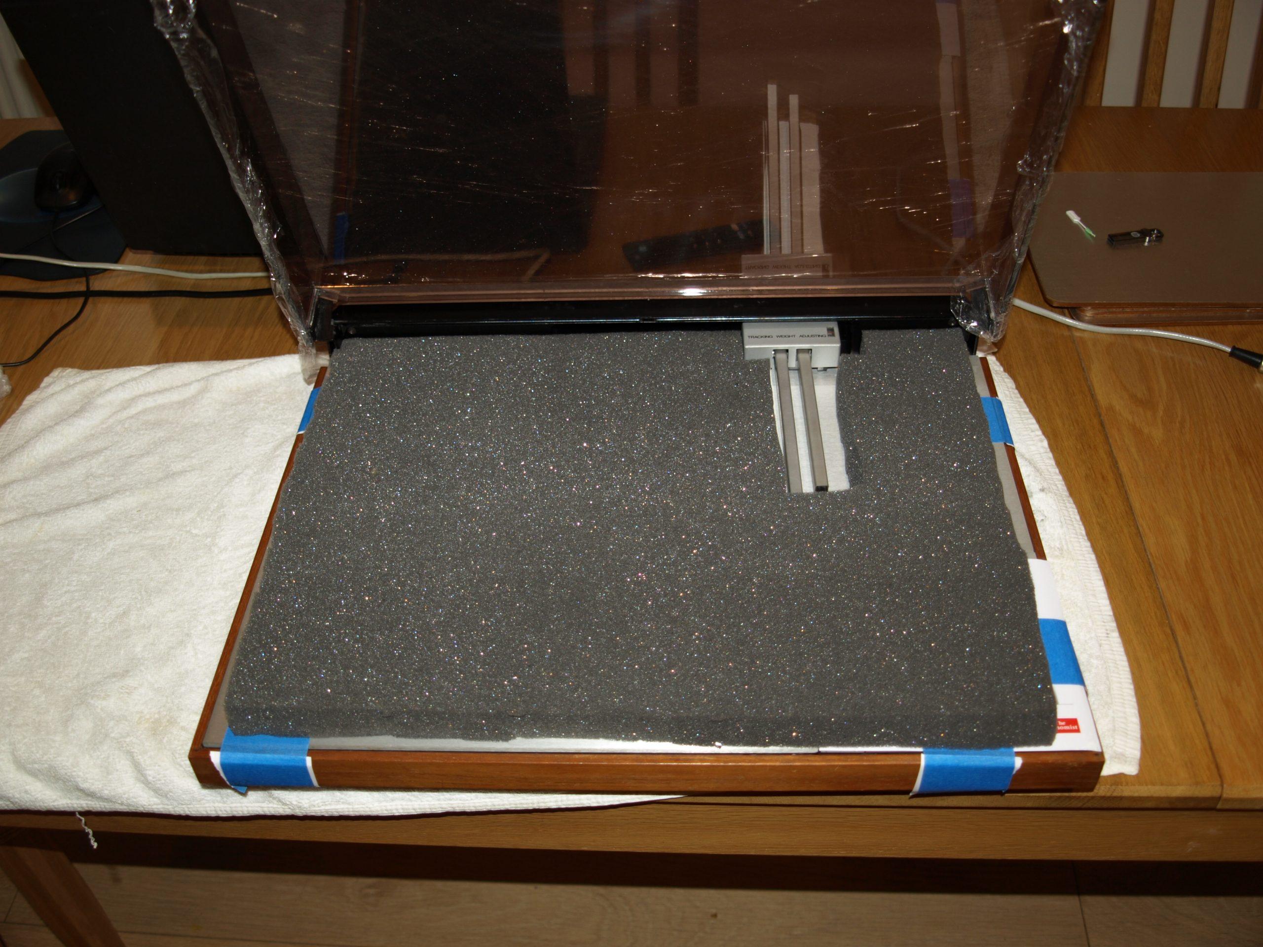
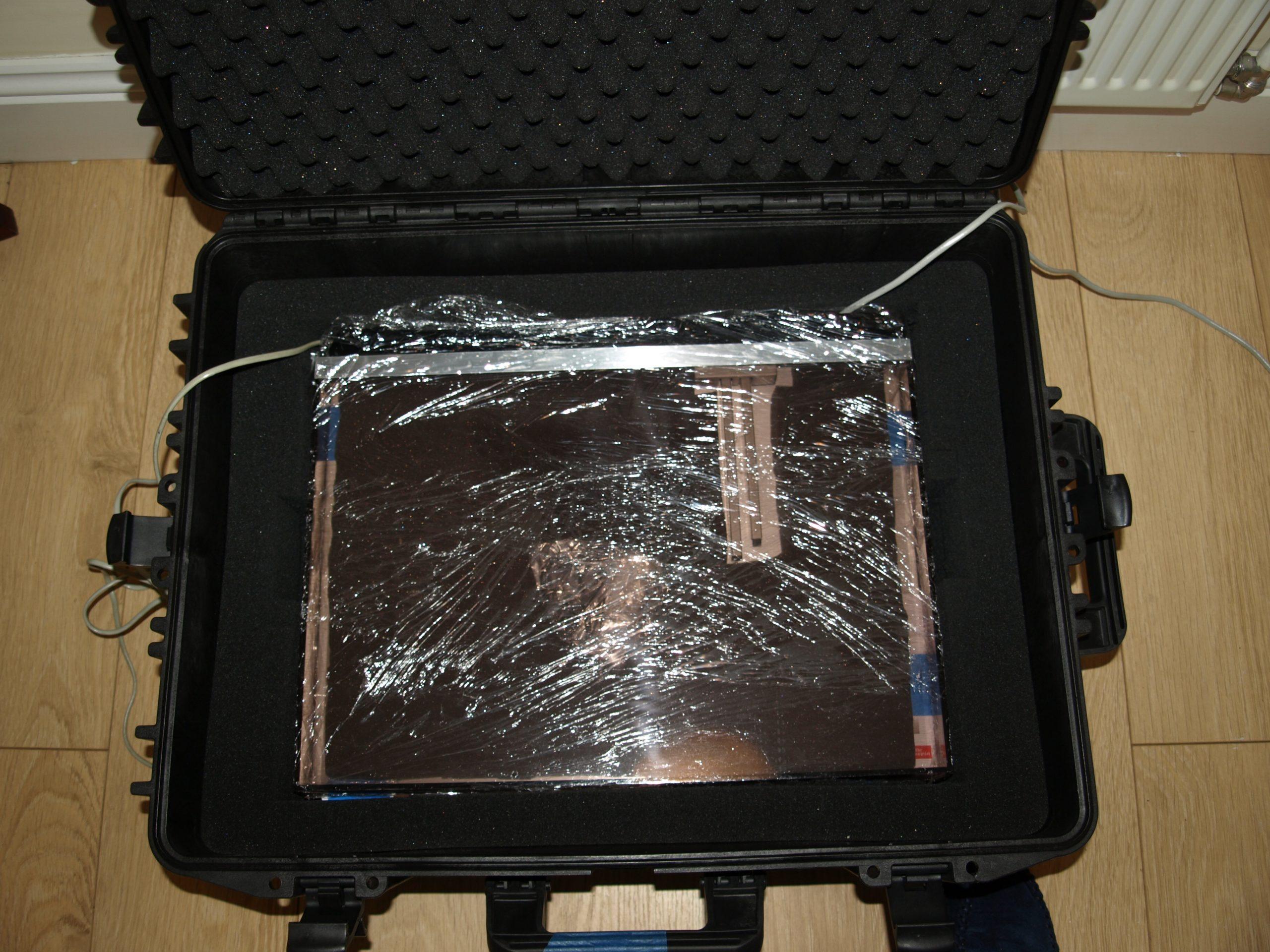
hcraig244SILVER MemberThe strong box is ideal for transit…
 hcraig244SILVER Member
All done and ready to roll…..
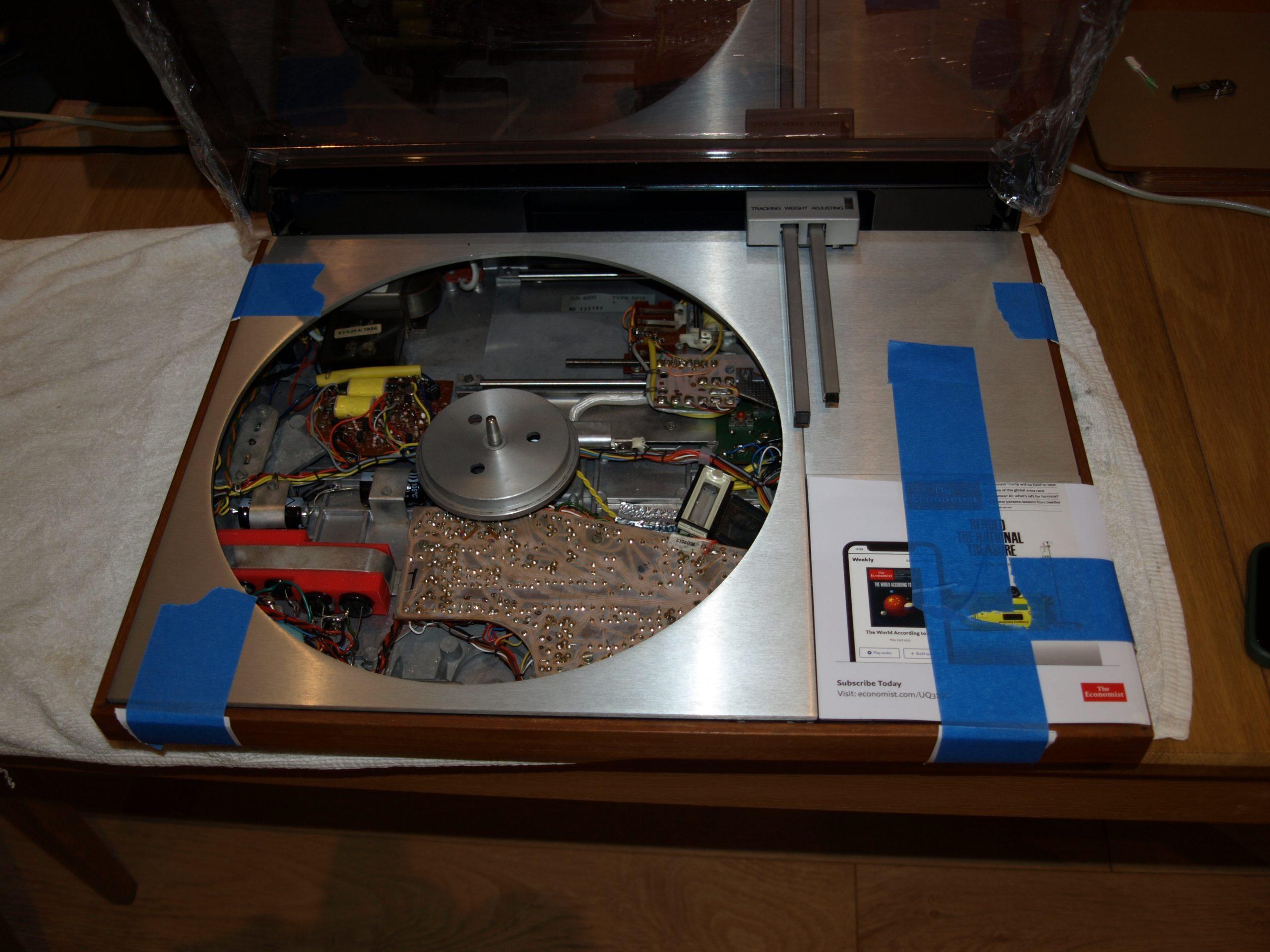
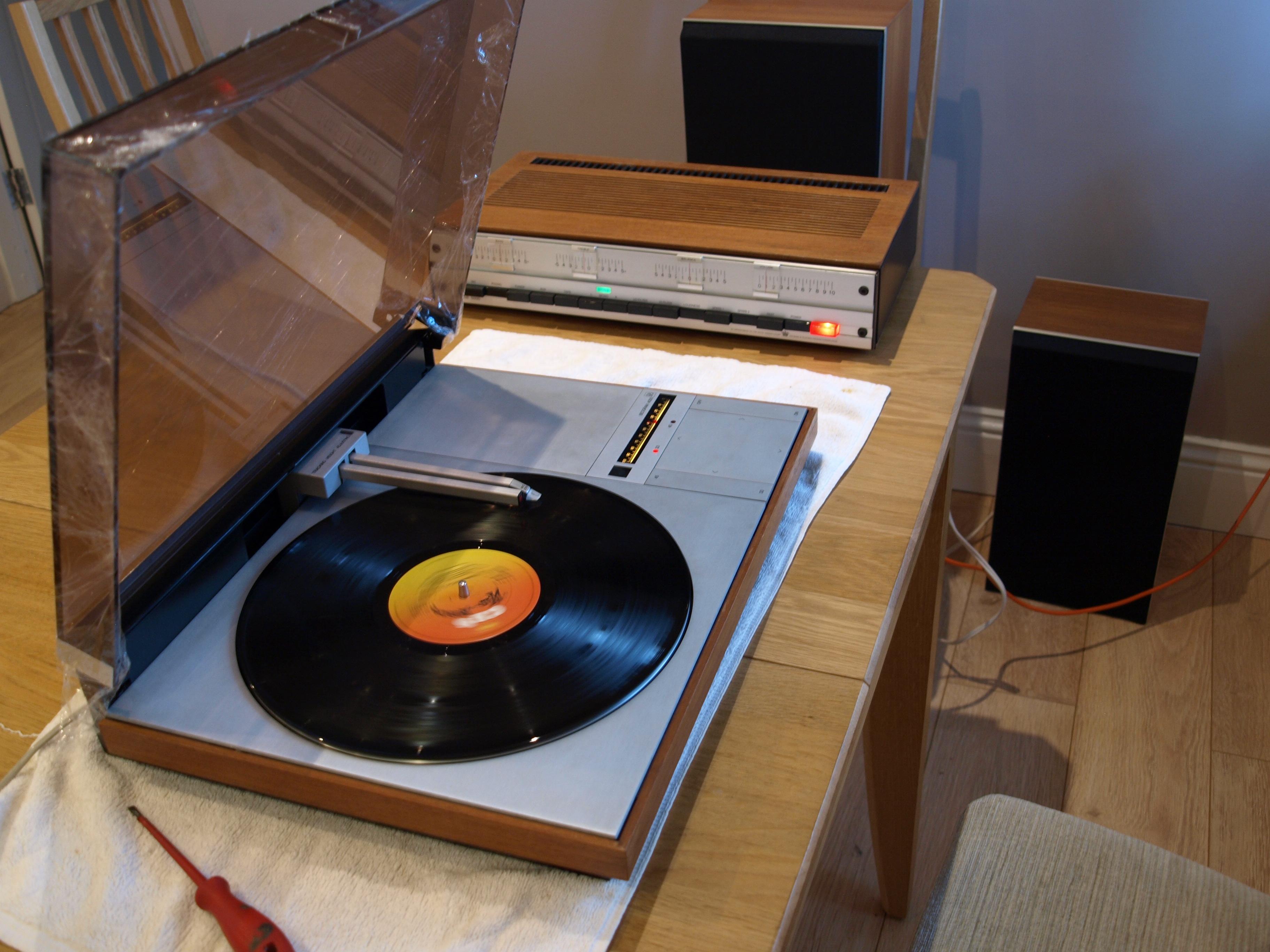
hcraig244SILVER Membercouldn’t resist posting this……
 hcraig244SILVER Member
Following a river cruise down the Nile to Luxor and the valley of the kings, something I’ve always wanted to do, I completed the test on this machine…..It’s easy to see why people fall in love with these engineering mastepieces
-
AuthorPosts