Forum Replies Created
-
AuthorPosts
-
 hcraig244SILVER Member
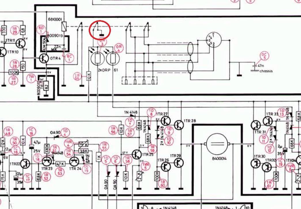
You may consider checking out diodes 1D8/1D14 also, you could also try exchanging the inboard drive transistors with the outboard drive transistors one at a time and testing as you go….if it is a failed transistor you will get to a point where you lose inboard and gain outboard travel.

I invested in one of these…….it has been a very usefull tool over the years, can test transistors and diodes
hcraig244SILVER MemberRead on through section 3.21….this gives a full description of the three functions associated with the drive for the transport system, you should be able to test the voltage levels at the associated transistor points when the control panel switches are operated, the notes are a little truncated and “solder ron” may be able to fill in the missing information as they where kindly donated by him.
Craig
hcraig244SILVER MemberSorry…..i misunderstood your problem, didnt realise everything was fine when playing a record.
hcraig244SILVER Member hcraig244SILVER Member
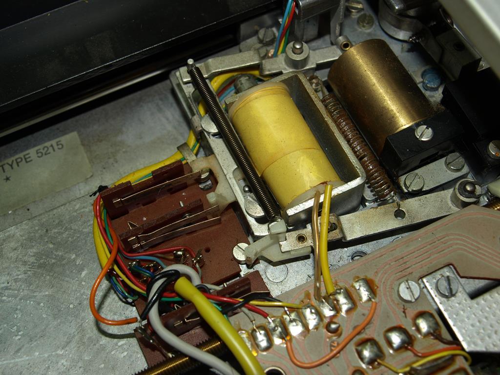
Ok…..check this set of switch contacts also…I know i keep banging on about switches but if nothing else you will eliminate them from the search. If these contacts dont operate your motor wont operate as a servo, the contacts should open when the solenoid energises.
 hcraig244SILVER Member
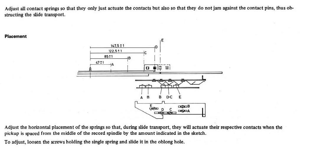
A very high percentage of problems experienced with these decks result from switches, either on the control panel or the transport slider. A switch out of position be it open or closed will play havoc with the boolean logic control gates, I have chased my tail for weeks trying to locate a problem that turned out to be nothing more than an intermittent sticking contact on a transport slider switch……an issue that had been identified as a possible cause by Dillen at the outset….however as it was intermittent when I tested the switch it worked fine…turned out that the silicone grease i had blobbed onto the plastic nipples (which I thought would help keep them free) was causing them to bind due to the viscosity……thorough cleaning and has worked fine since…….I’m rambling I know ;¬)
Craig
hcraig244SILVER Member
Ok…..start by checking the switch contacts on the carriage transfere mechanism, sounds like this unit has been stood idle for a while, they are a little awkward to get at but sounds to me they will need cleaning even if they are not responsible for your problem. Dont adjust any of the position screws.
Craig
hcraig244SILVER MemberDont force it…..let it soak, WD40 isn’t popular on this site (I think the popular term for it is snake oil ) De Oxit is the cleaner of choice, however i would go for something like 3 in one penertrating oil…..leave it overnight.
Craig
hcraig244SILVER MemberRead/view this rom beolover
hcraig244SILVER Member hcraig244SILVER Member
Are both your tuning lamps working fine?
hcraig244SILVER MemberWhere did you get that lovely Beo Hub board from? I did have to replace a reed switch and a blown transistor on mine (TR6 I think?).
I have also had to replace the reed switch on a couple of these units, usually after i have invertedly grounded the 6vdc circuit…..its happened a couple of times when the carriage slide has moved too far in when i have been testing with the slider switches removed (schoolboy error)…..
hcraig244SILVER MemberYou haven’t said if your measuring a voltage drop when the volume falls down….have you monitored this yet…i so is it falling off?
If you upgrade your membership to silver you will have access to the service manuals for mostly every B&O amplifier available…….
hcraig244SILVER MemberFirstly….is the existing fuse blown? no need to replace it if its good….I would buy a couple because often when you take these out the end cap becomes detatched and the fusewire pulls out of the glass holder, the fuse is 0.4A and sits in approx 14vac circuit.
The high temperature that has discoloured the yellow sleeve is heat generated from the voltage regulator circuit 2D4 (ZF6.8) 2R22 and 2TR6…..the fuse isn’t responsible for generating heat, this discolouration is very common as the regulator circuit does run hot…before you reconnect the fuse check you have the approx 14vac measured between the blue wire connected to the fuse and the blue wire connected to the PCB just above the rectifier…..this will confirm you transformer is giving the required voltage.
Craig
hcraig244SILVER MemberMade a mess of that…..the table shows the voltages that should be present at TP14 for mute on or off.
hcraig244SILVER Memberhcraig244SILVER MemberWhat do you measure on the input and output of the bridge rectifier 2D5 ? and have you checked the fuse hiding inside the yellow sleeve from the transformer to 2D5 ?
Craig
hcraig244SILVER MemberIf your only input is currently the FM tuner your problem may be the muting circuit?
Craig
hcraig244SILVER MemberOne way of determining if the 15v rail is falling off is to monitor the power ON lamp as this is fed from that supply.
Craig
hcraig244SILVER MemberAnd incidentally one way of testing the thermistor is to blow a hairdryer over it and the fault relay should activate and shut the amp down.
Craig
-
AuthorPosts