Forum Replies Created
-
AuthorPosts
-
 hcraig244SILVER Member
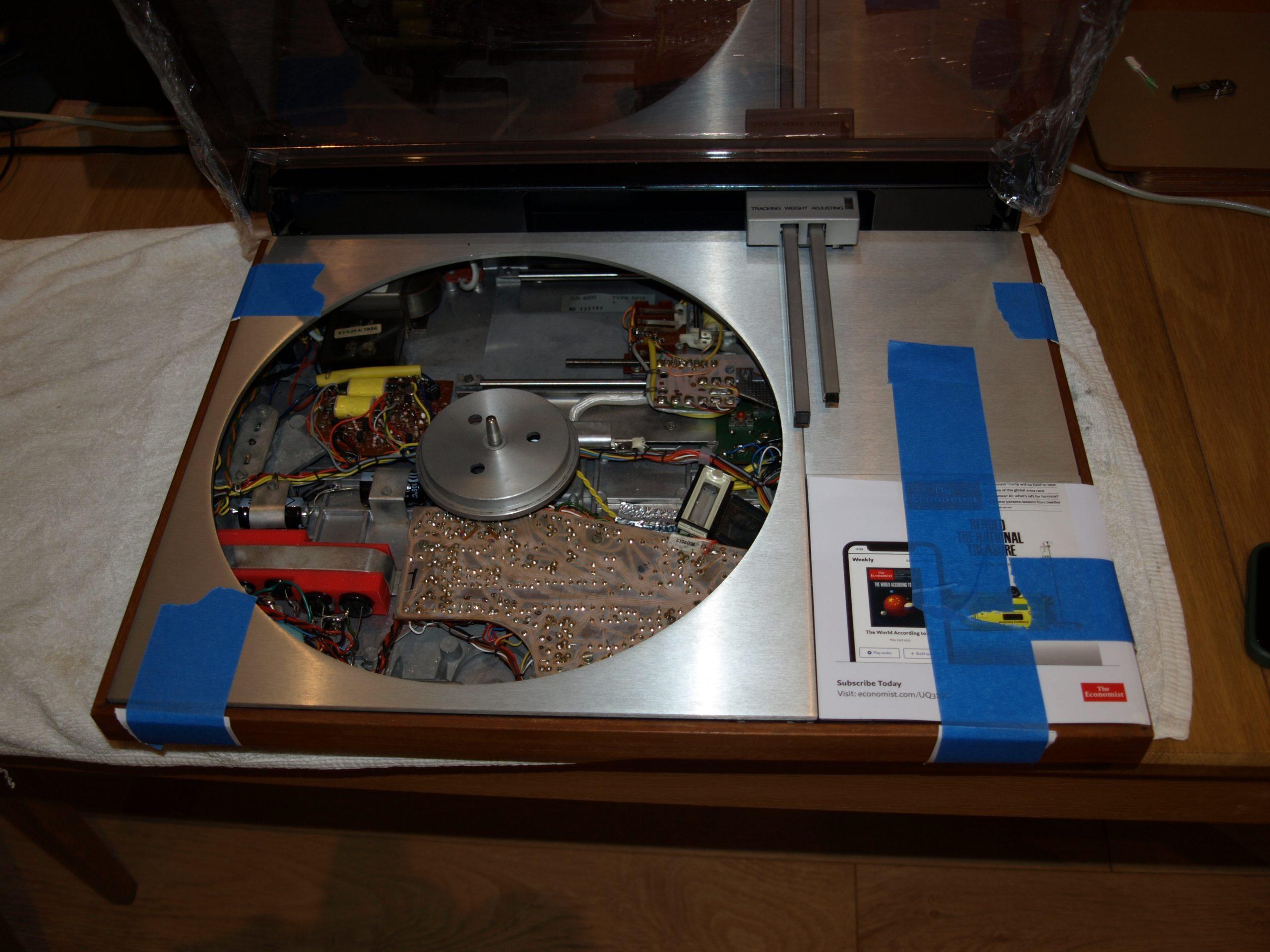
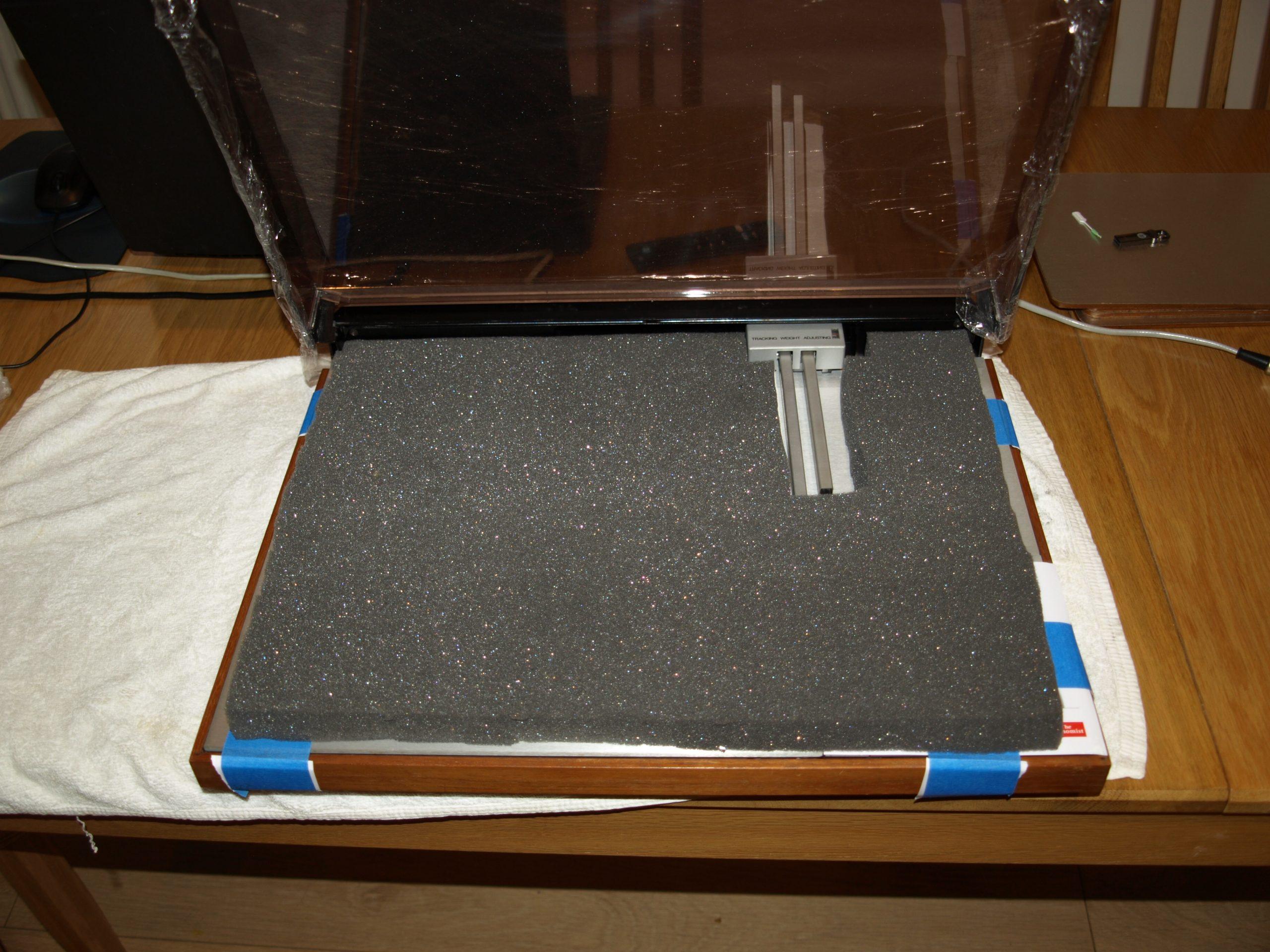
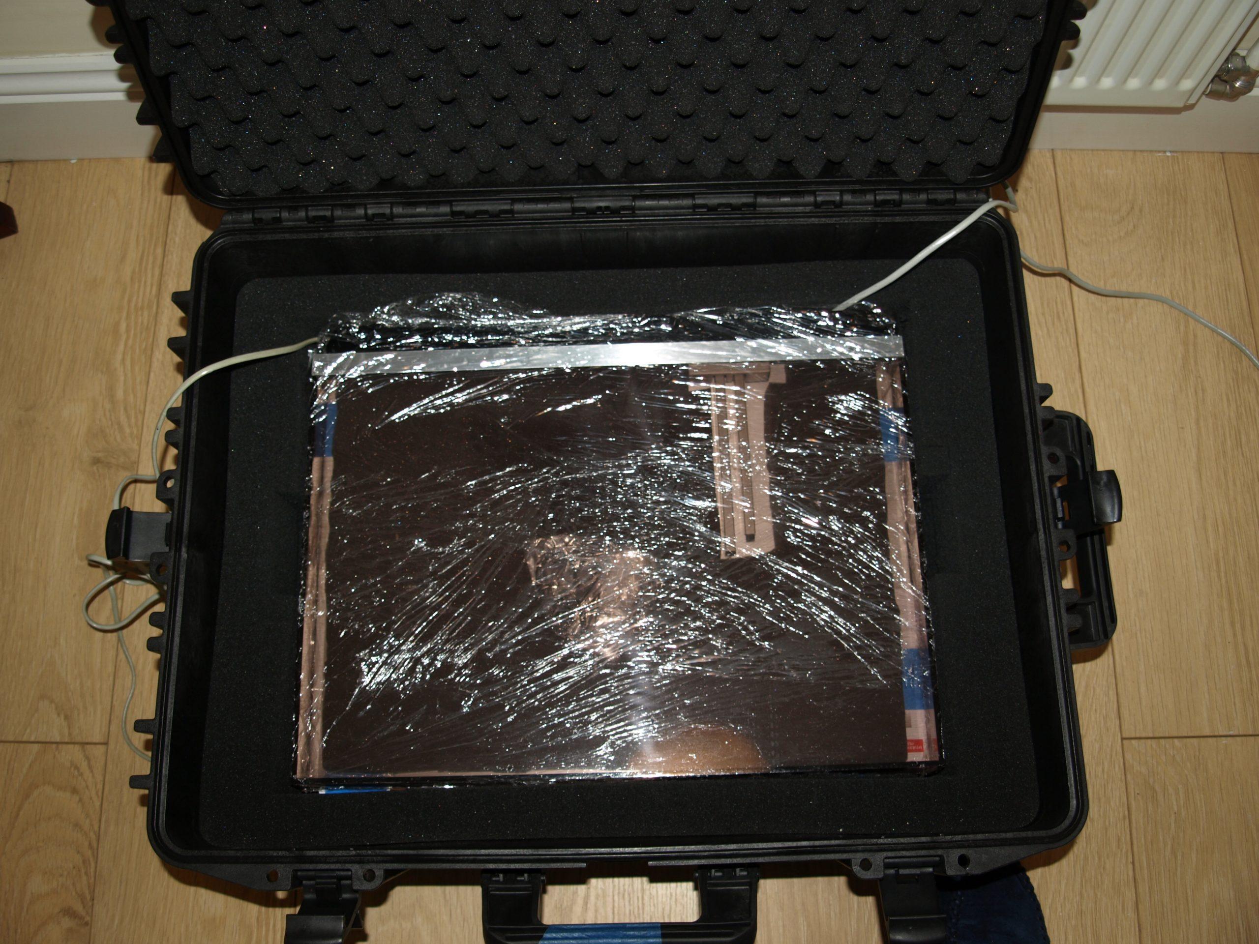
The strong box is ideal for transit…
 hcraig244SILVER Member
All done and ready to roll…..
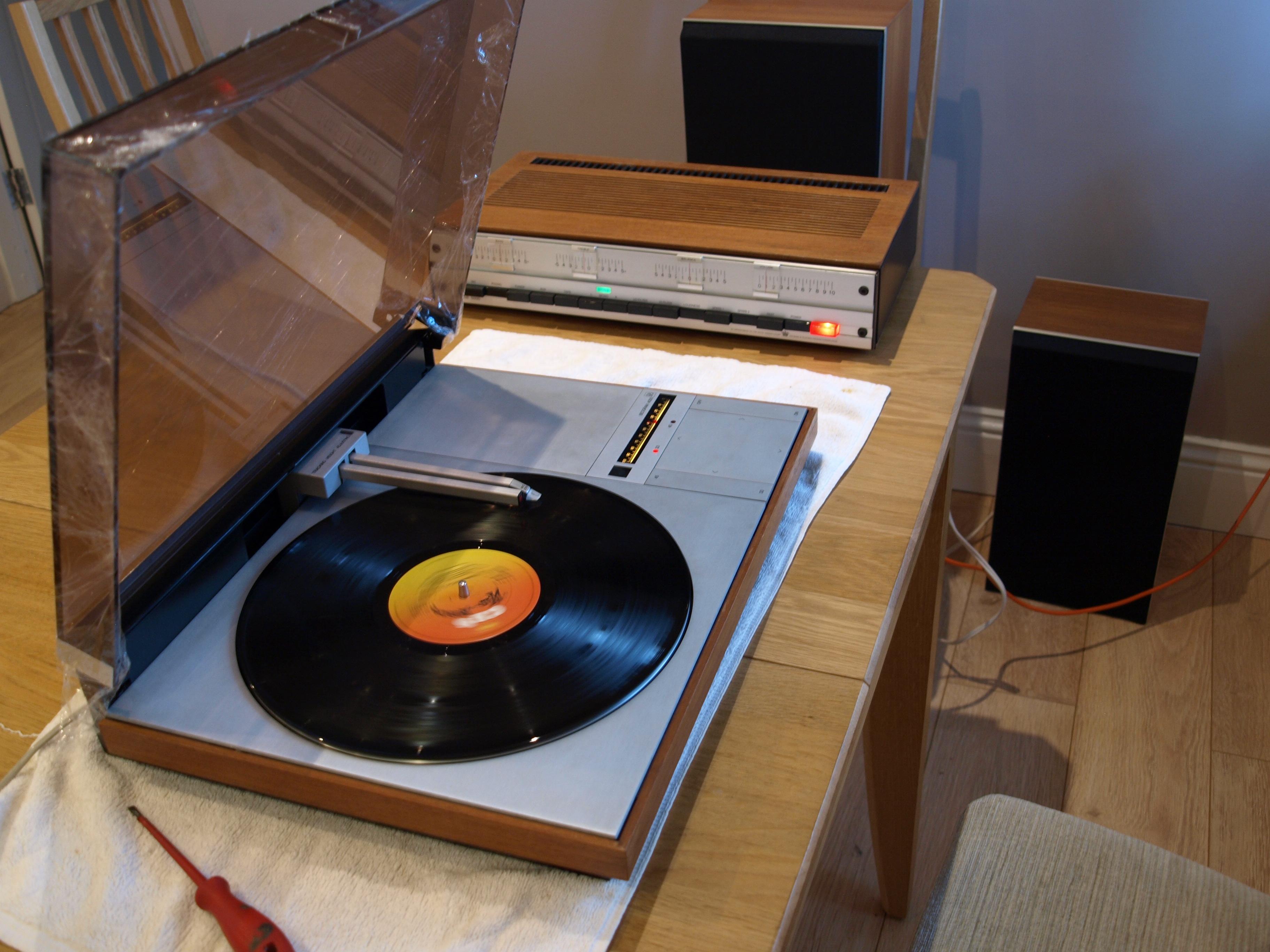
hcraig244SILVER Membercouldn’t resist posting this……
 hcraig244SILVER Member
Following a river cruise down the Nile to Luxor and the valley of the kings, something I’ve always wanted to do, I completed the test on this machine…..It’s easy to see why people fall in love with these engineering mastepieces
hcraig244SILVER MemberThese switches are notorious for failure due to arcing damage…..it’s quite possible the reason for your issue, very difficult to repair/replace too ?
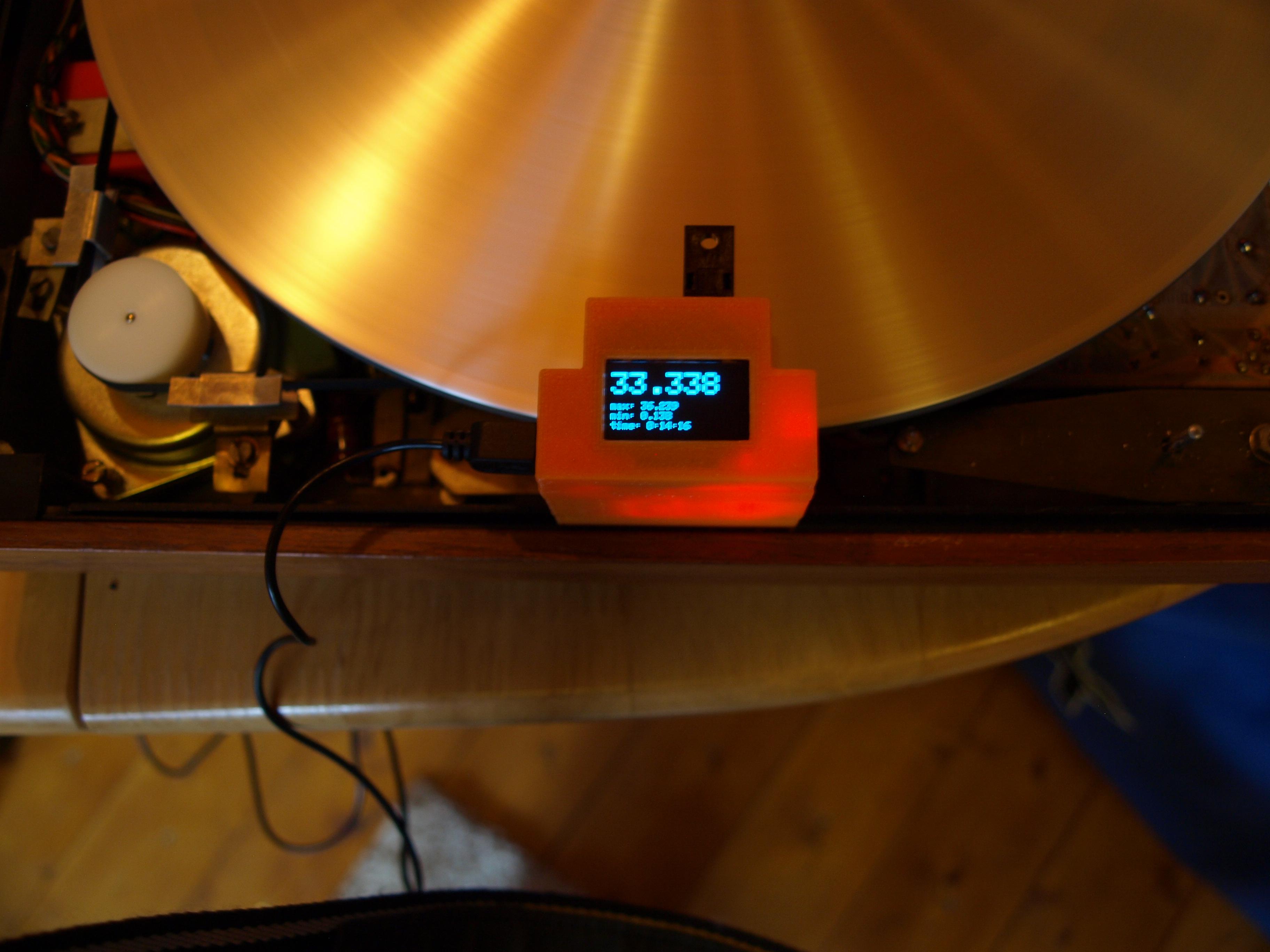
hcraig244SILVER MemberQuickly moving on…….as the deck came to me bereft of cartridge I fitted one of my own and gave it a test
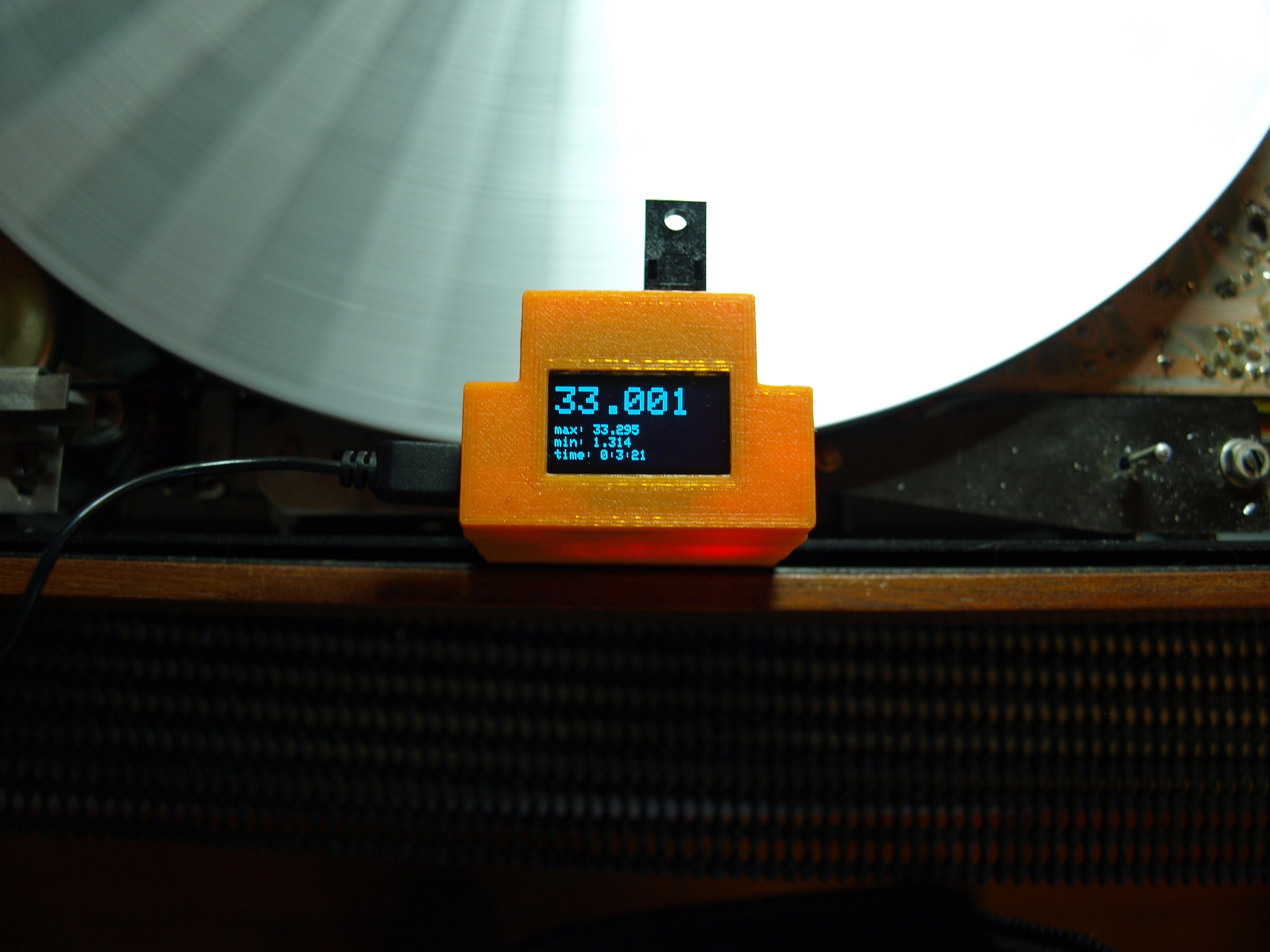
hcraig244SILVER MemberWell……isnt this a little embarrassing, fortunately Glitch is paying attention and identified the schoolboy error regarding the 33rpm setting. should of course be set to 33.33rpm…the manual identifies the 33rpm setting should be set up using the stroboscope dial which no doubt is calibrated to give a 33.33rpm setting when appearing stationary…..oops
hcraig244SILVER MemberAll that remains is a period of testing……
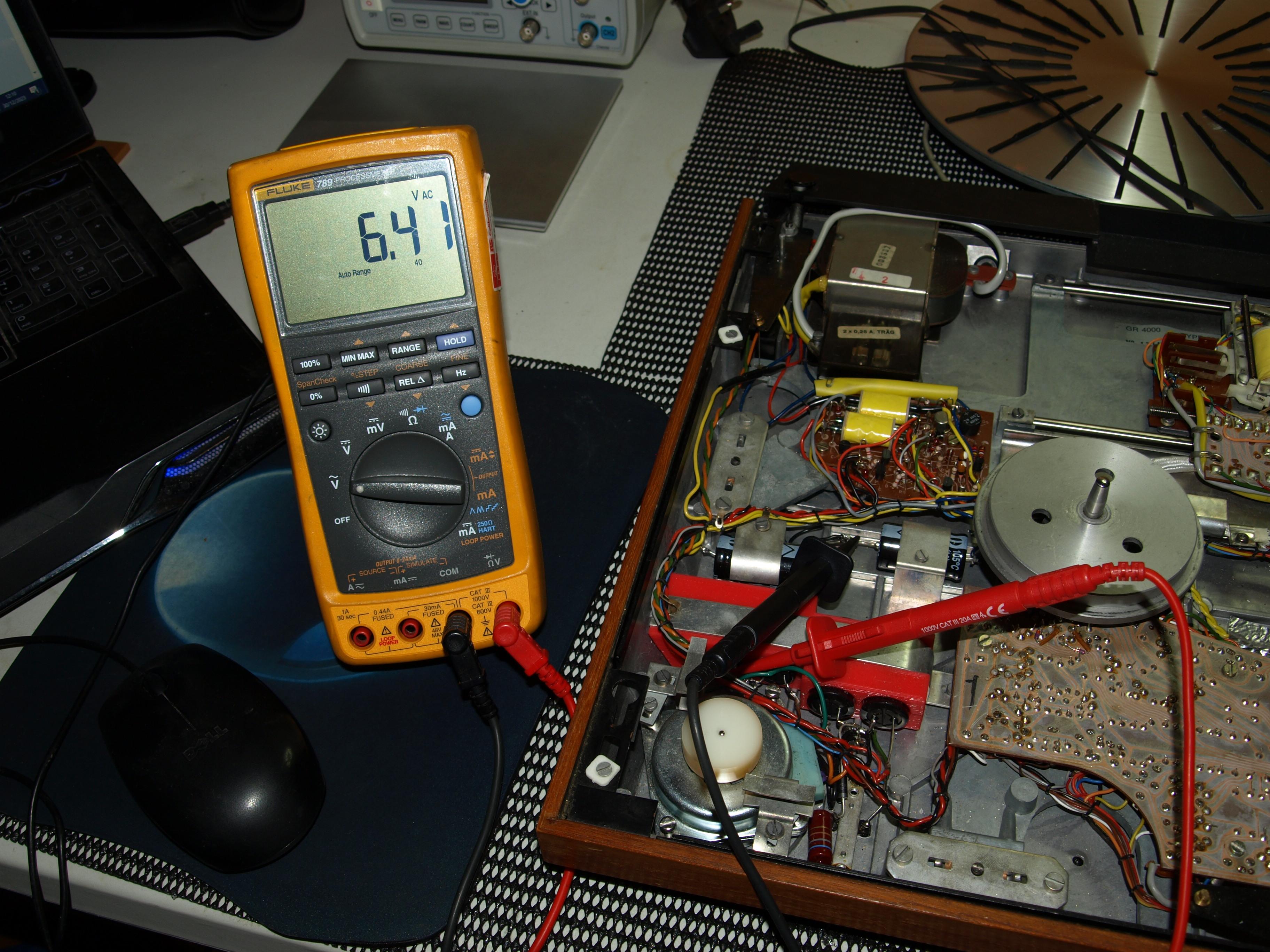
hcraig244SILVER MemberFairly straightforward with the exception that X is now in a different place due to the modified capacitor arrangement provided by Rudi….the Bi Polar capacitor position is now after the two back to Back capacitors…..measured up fine.
hcraig244SILVER MemberAdjustment of voltage for drive motor
 hcraig244SILVER Member
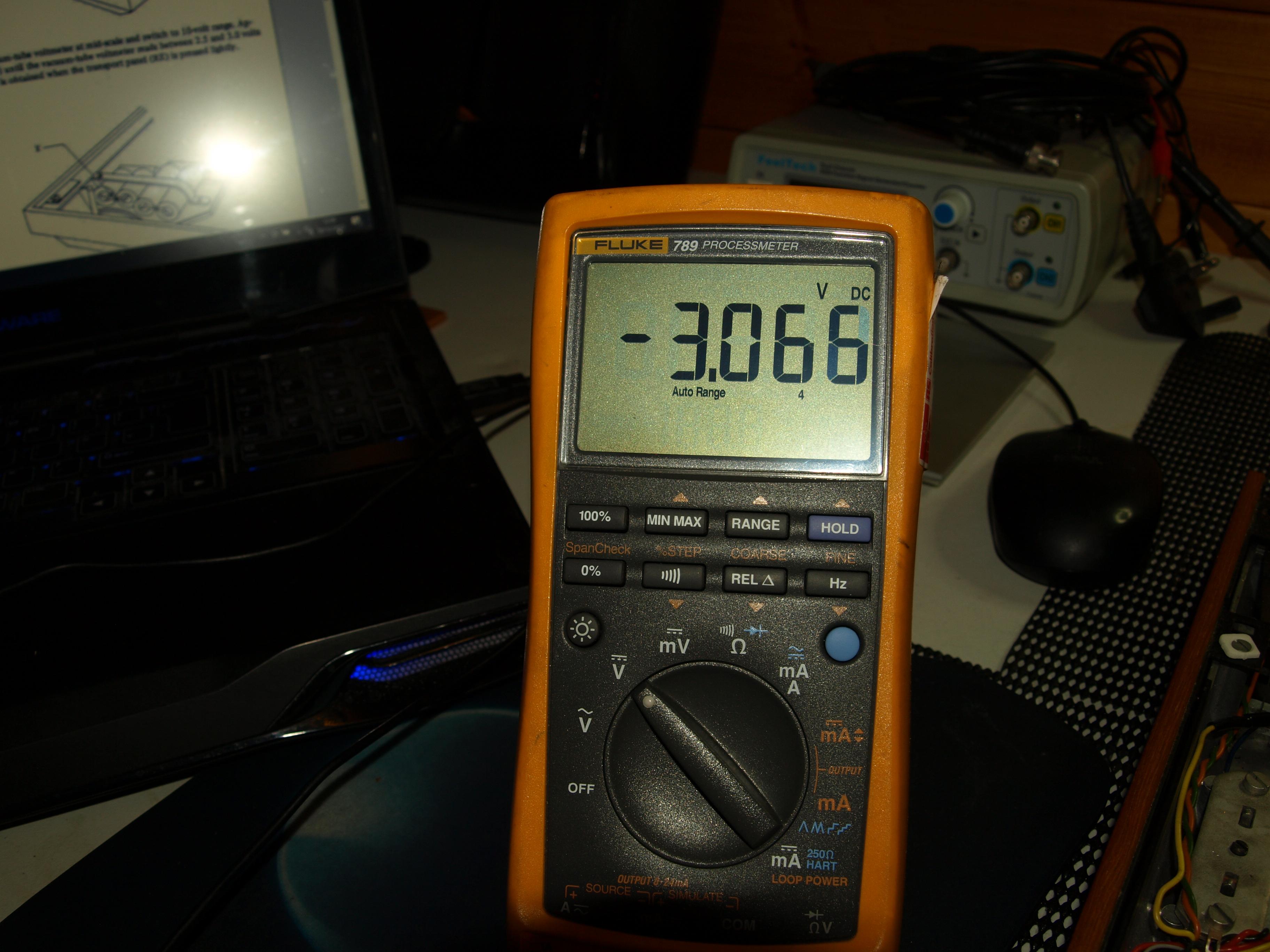
Reverse was a little off….so had to adjust somewhat, so its always good to check. oh and swapped the probes around.
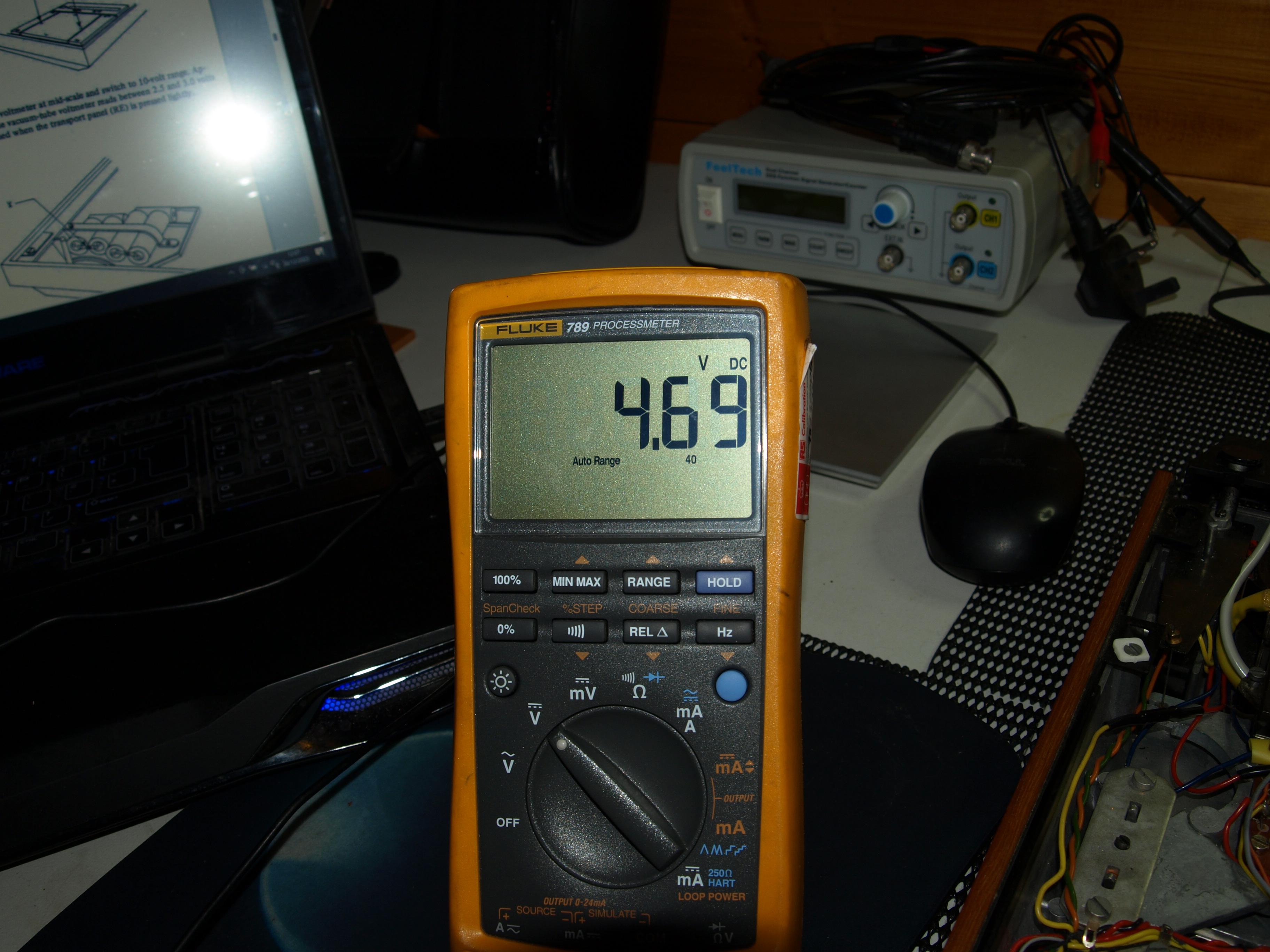
hcraig244SILVER MemberThis went well……forward measurement, got the probes wrong way around naturally, measured up fine
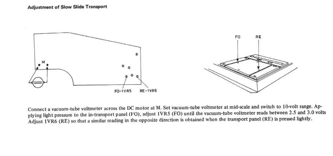
hcraig244SILVER MemberAdjustment o the slow slide transport……..
 hcraig244SILVER Member
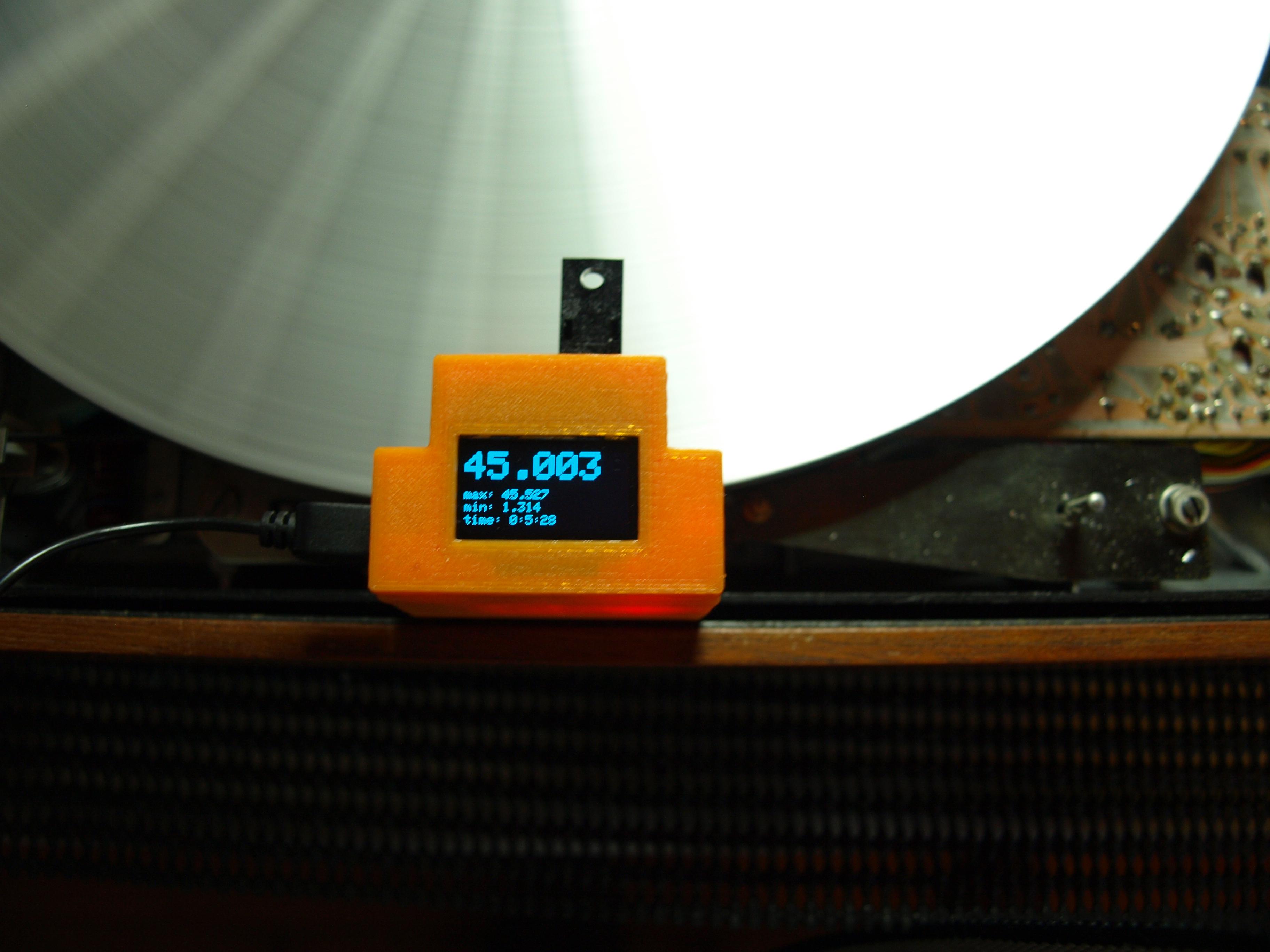
45rpm was a similar story….tweeked that trimmer also
hcraig244SILVER MemberSo tweaked it in……..
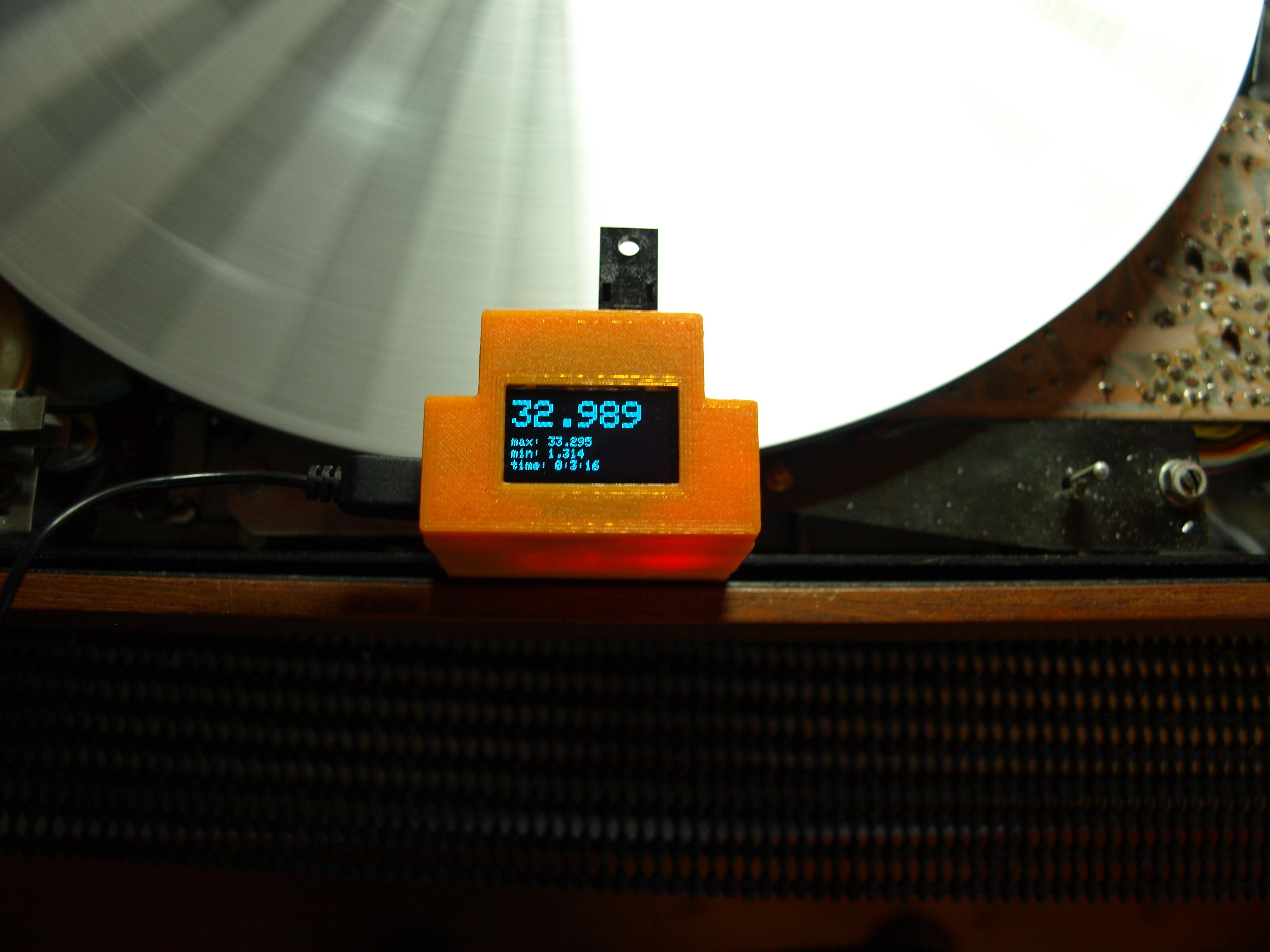
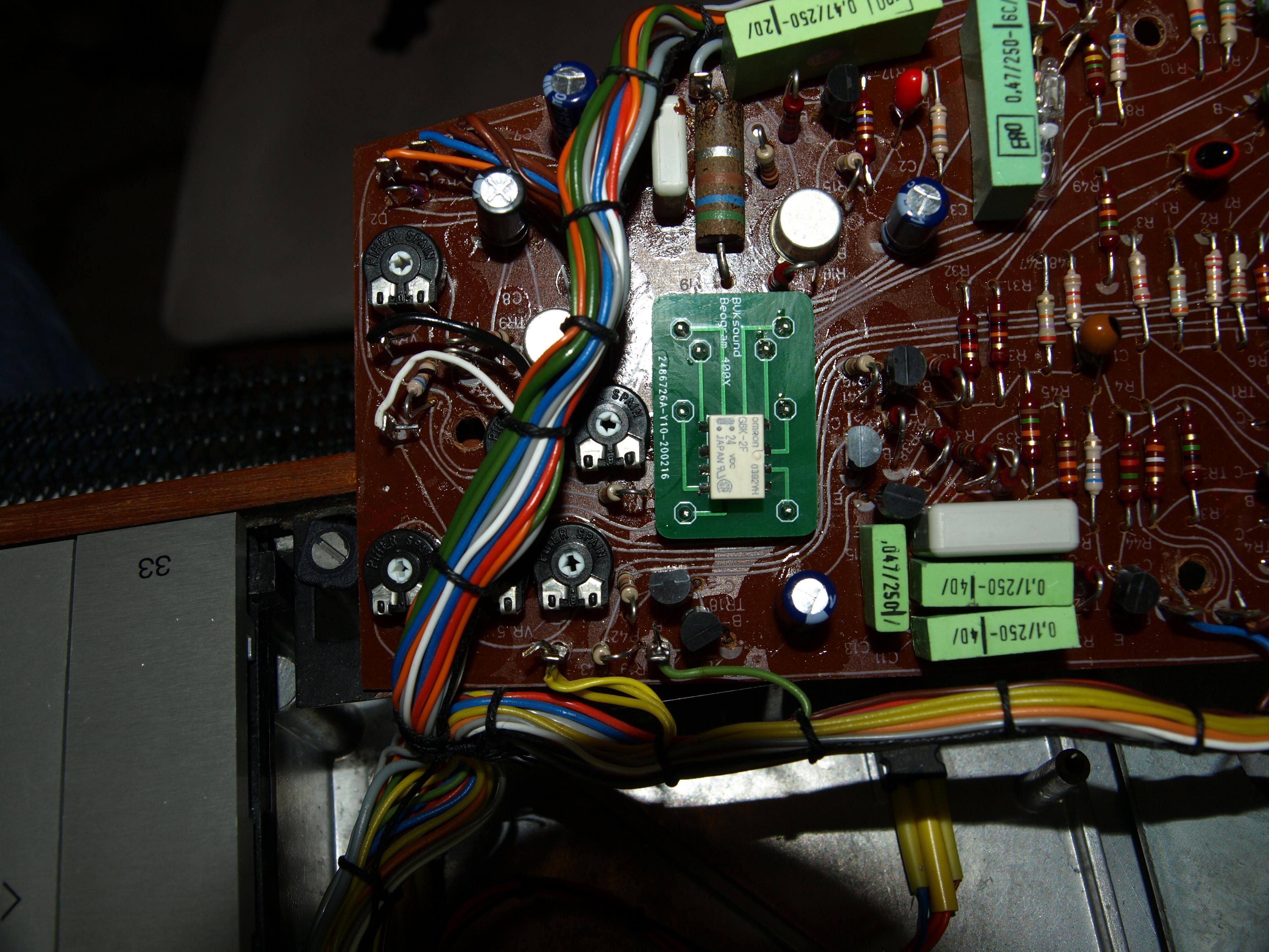
hcraig244SILVER MemberJust need to do some adjustments following the trimmer replacements…I don’t expect them to be far away as I measured across the relevant legs of each one and set the new trimmers accordingly but doesn’t hurt to check……used Rudi’s digital tachometer I purchased for the very purpose…..seems a shame not to use it. 33rpm up first and it was a little off…
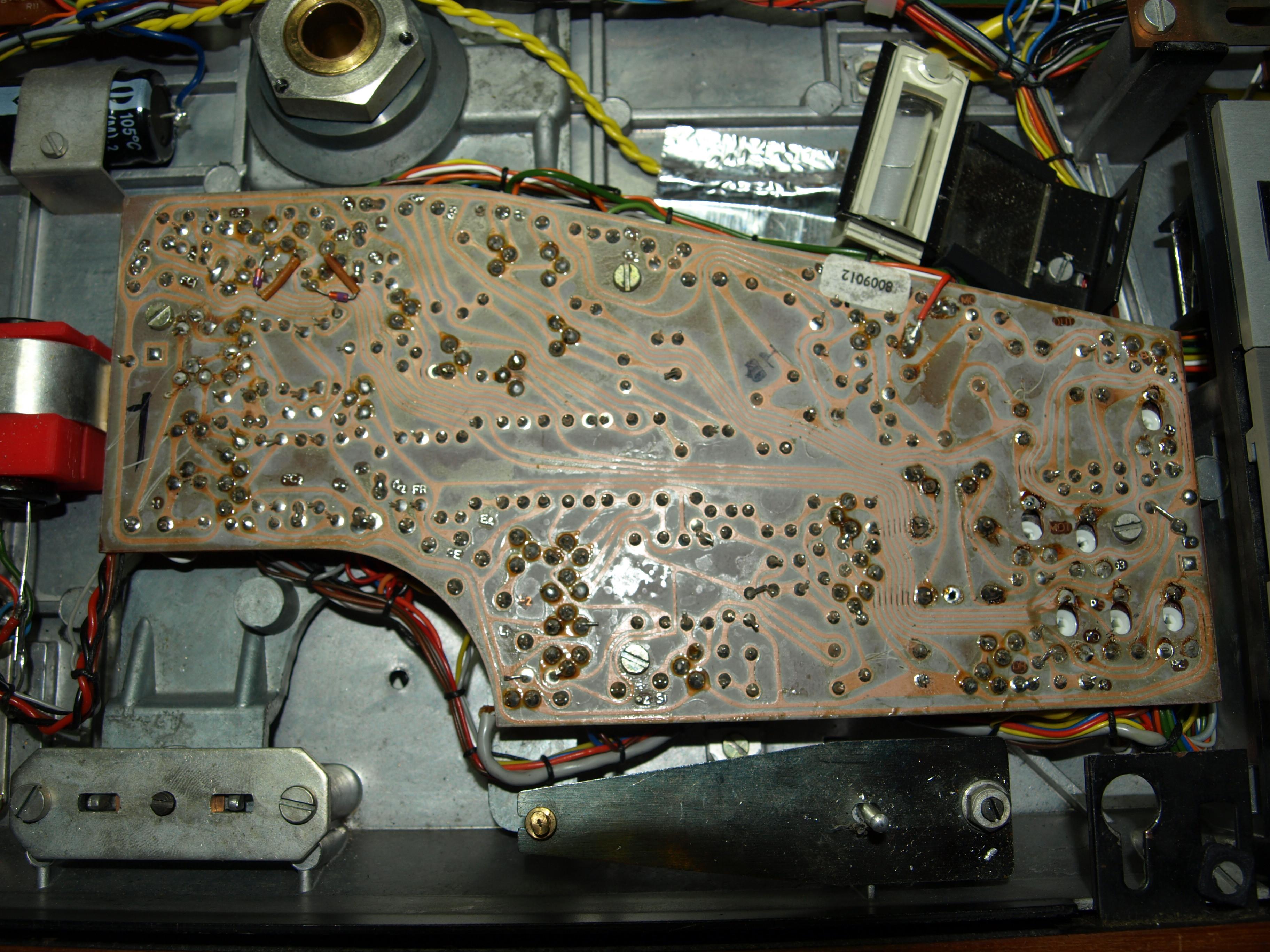
hcraig244SILVER MemberAnd had a dig around in my box of miscellaneous odds and ends and located some machine screws to fix the PCB in place.
hcraig244SILVER MemberGot around to replacing the skeleton trimmers today, not that they where suspect in anyway just because they probably will fail at some point.
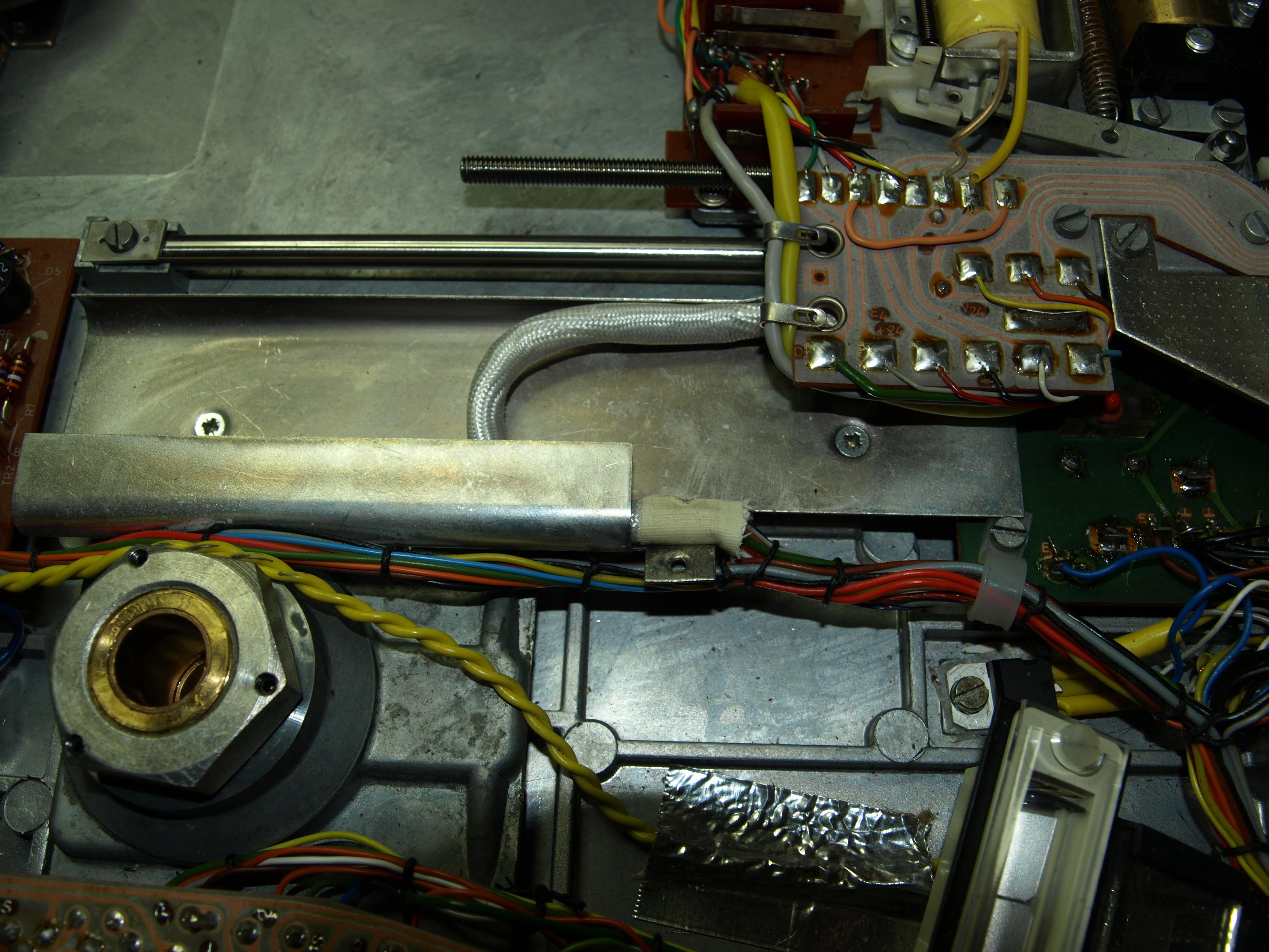
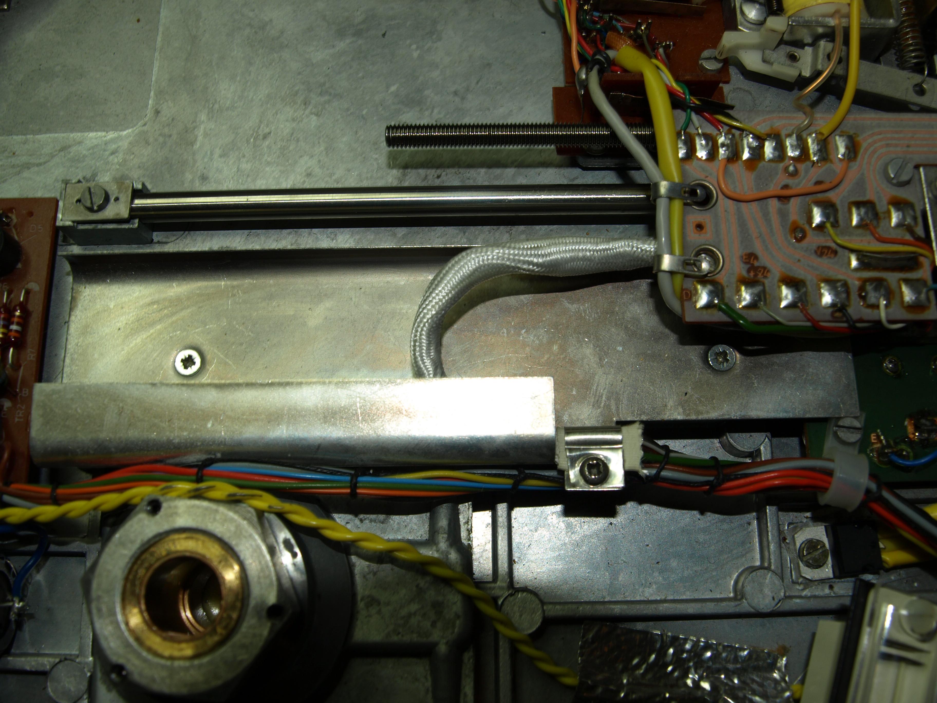
hcraig244SILVER MemberUnclamped the sock and rotated it to remove the kinks…..this is much happier now, never seen this before……will re secure the clamp and look to replace the trimmers.
hcraig244SILVER Memberduring testing I found that when the tone arm approached the ES position it was slowing down considerably, when moving forward slowly by nudging the tone arm by small increments to simulate a record on the deck, and more often than not actually stopping short.
I noticed that the drive motor was still running and the belt was slipping….watching this a couple of times i spotted this..the cable containment sock was all twisted and lumpy and the carriage was fouling on it at the end of its travel…
Tht
-
AuthorPosts