Forum Replies Created
-
AuthorPosts
-
 hcraig244SILVER Member
Did you replace the tuning lamps?…..I haven’t worked on a BM2000 but I do know that if one changes the lamps on BM4000 they must be the correct mA rating or it causes issues with the rest of the circuit….Dillen (Martin) from the site may be able to supply the correct lamps if thats the case…
Craig
hcraig244SILVER MemberLooks like the nozzle from a windscreen wash, I bought a wine bottle vacuum pump when I was considering infusing one of my BG4000 motors….however when i put it on test and mapped it using one of Rudi’s tachometer devices, downloaded the readings to Excel to produce a graph I found the speed was very consistent so haven’t tried it yet. It’s something I will do when the time comes more out of interest than anything else…
hcraig244SILVER MemberBest if you dont apply that adage to the cam belt on your car ;¬)
Craig
hcraig244SILVER MemberGravity….
Martin (the oracle of all BG4000 knowledge) would frown on replacing the tantalum capacitors with electrolytics, he did explain the reason for this in a previous post of mine when I performed a similar restoration on a BG5000, I do know there are advocates of the replacement with electrolytics (Rudi) however I went with Martins advice and put new tantalums in. You should replace the old electrolytic capacitors with new as they will have dried out and as Christian says change out the skeleton trimmers for new piher sealed trimmers, do this one at a time measuring the settings of the existing one (as best you can) and run the deck, adjusting the trimmer if required, to ensure all is well before moving on to the next one….that way you will know just where to look if things stop working (poor solder joint etc)……so far so good ;¬)
Craig
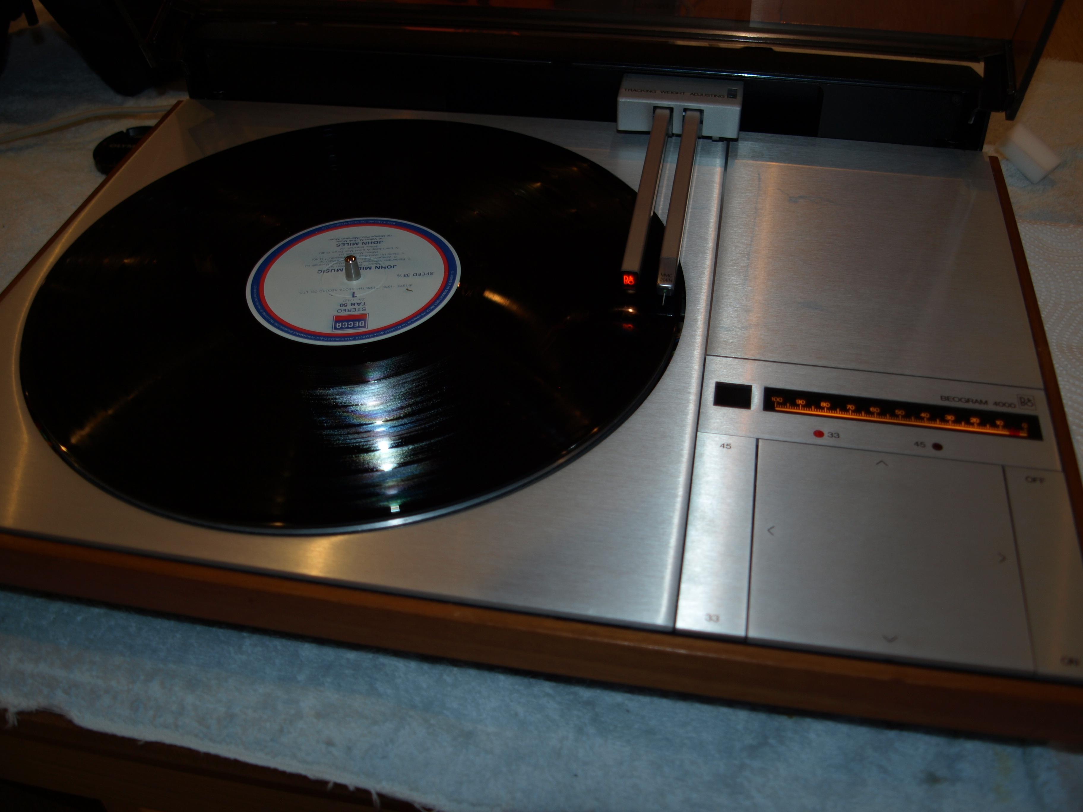
hcraig244SILVER MemberSome pics would be good Graham….
hcraig244SILVER MemberSounds like a problem with the servo…..the shutter adjustment could need adjusting. Silver members can access the service manuals which describe how this can be carried out, I haven’t done much work on the 4002 many in here have….im sure someone will advise you further, my advice is to go silver and download the service manuals
Craig
hcraig244SILVER MemberDave
I will run it periodically before you come and collect….if it happens during those tests I will document it here ;¬)
Craig
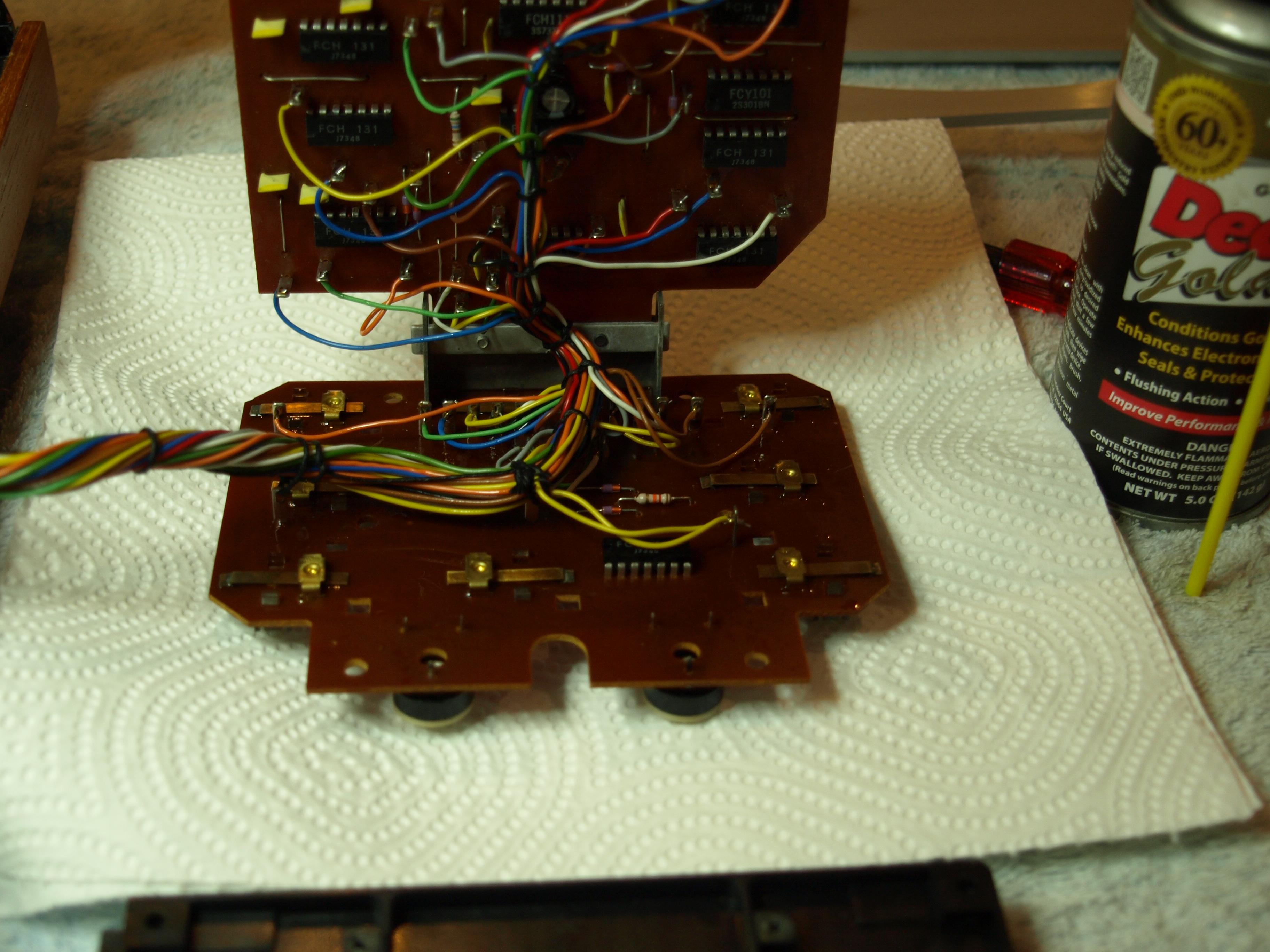
hcraig244SILVER MemberNever use WD40 for anything other than blinding burglars ;¬) deoxit seems to be the solvent of choice in this forum….I used to use servisol until I converted…….
Craig
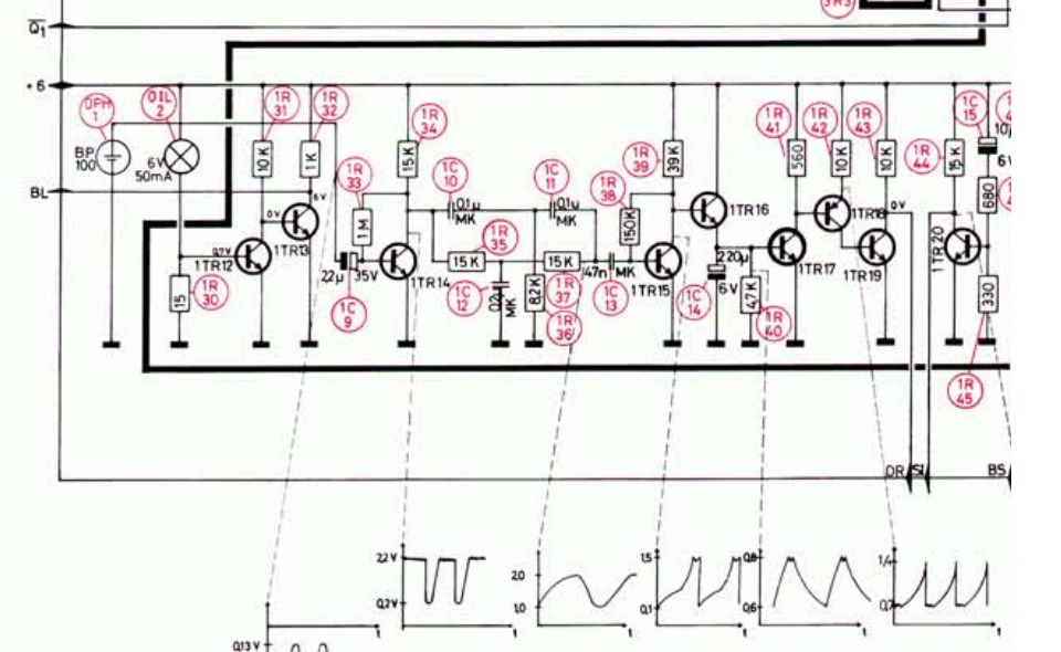
hcraig244SILVER Member“The first is at the base of 1TR14 and the collector of 1TR17”
Looking at the schematic I dont see a point showing a scope reading at the collector of 1TR17 ?
 hcraig244SILVER Member
The main forum product section contains manuals for the BG4000 and also some training notes donated by a member who was a one time repair engineer who went on a training course and reatained the course notes…..these notes identify the abbreviations and are a very usefull guide…..they are available to silver members and above, take a look…..do you have a transistor tester available?…….seems like your machine is only a short way from being sorted…..
hcraig244SILVER MemberIs the platter spinning with the tone arm over the rotating ribs in the scope readings?…..looks like it is….so the photovoltaic cell looks like its still working, good news.
Are you sure the readings are taken at the points you identify above? and as the tone arm will drop under some conditions then the solenoid and associated linkages/damper pot etc are all working, more good news.
I think the potentiometer you refer is the one installed to enable playing transparent disks? does the tone arm stop at the correct place when a disk is played….or just run to the left side then run back to the rest point?
Craig
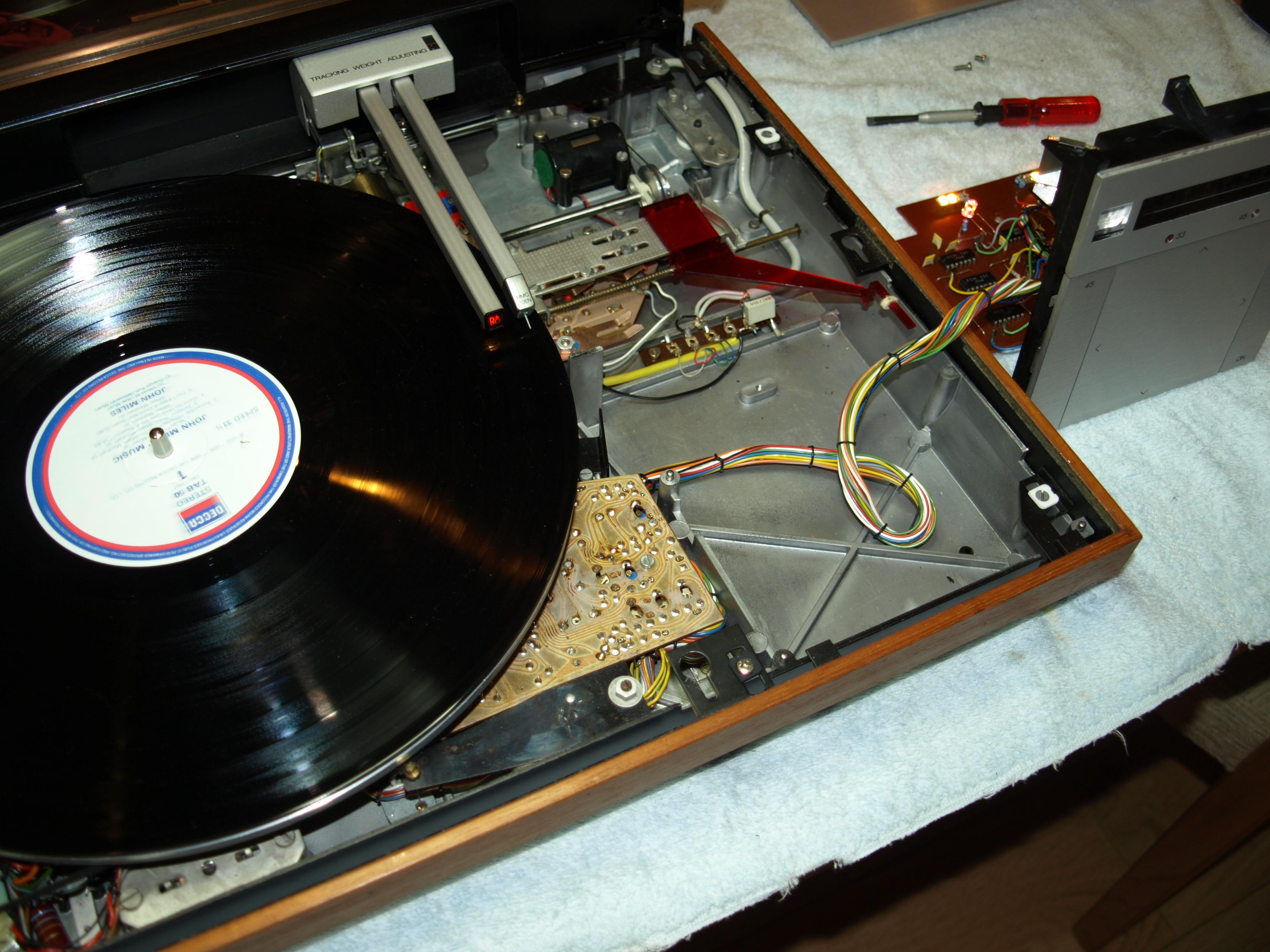
hcraig244SILVER MemberAll reassembled and functioning flawlessly………very odd. However I will fire her up again from time to time and see if the issue returns…..I still suspect a sticking switch or switch nipple on the control panel.
Craig
 hcraig244SILVER Member
Had a look at the leaf spring contacts and they look clean, gave them a squirt of Deoxit non the less…..once dry I will re install the control panel and try it again….I do recall having issues in the past once the panel screws are tightened down, i think if they are not evenly tightened they flex the PCB causing erroneous signals…….
hcraig244SILVER MemberWell……..got to this today, removed the control panel for a visual inspection and all looked fine, ran her up and she works perfectly?…….
hcraig244SILVER MemberMartin
Whats the best way to do that?…..
Craig
hcraig244SILVER MemberAlf
The service notes say “speed switching (33-45rpm) is performed by altering the values of R1 and R2 so that the oscillator frequency will be approx 42 and 59hz respectively” seems to me if everything works fine on 33rpm that the oscillator is working fine, could be wrong of course…….have you checked the trimmers and associated solder connections?
Craig
hcraig244SILVER MemberSend me a picture ?
hcraig244SILVER MemberDillen (Martin) from this site is your man……he can supply the correct lamps for you, send him a line.
hcraig244SILVER MemberJust spotted this post justin, picked up a chest infection from soewhere ;¬(
The tone arm dropping sharply sounds like not enough dampoing, try winding the srew in very slightly…..and I would check out the down switch contact…..if its playing up the tone arm will dot stay up when ^ is pressed
hcraig244SILVER MemberFound this in a 2012 – 2022 archived post “justins BG4000”
Powered up and this is what transpired:
unit sat powered up with no actions
upon hitting Start the platter drive started up at 33rpm
the panel ilumination lamps came on
the 33rpm speed selector lamp cam on
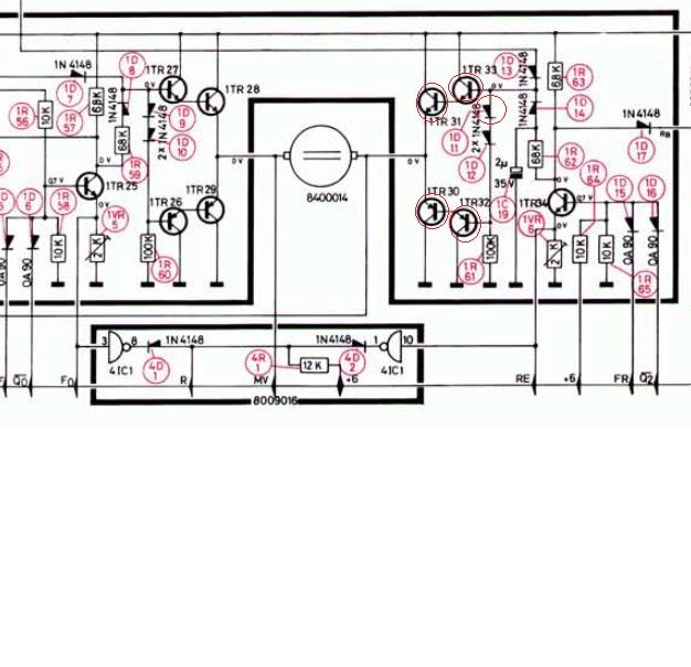
However the transport drive motor didn’t run, I could change the speed from 33rpm to 45rpm but no other functions responded. Time to look at the circuit diagrams……This is what I found….the following components where shot:
1D11 Diode
1TR33
1TR31
1TR30
1TR32
All of the components on the opposite side of the motor tested good.

-
AuthorPosts