






Home › Forums › Product Discussion & Questions › BeoLab › BL3500 and the MCL/PL connector
Tagged: Beolab3500
- This topic has 155 replies, 11 voices, and was last updated 1 month, 2 weeks ago by
 swo.
swo.

-
AuthorPosts
-
21 August 2026 at 13:34 #125117
 swoGOLD Member
Beolab 3500 Mk II
Tested with SW 3.33When the Beolab 3500 Mk II is in PL mode, it behaves like a normal BL speaker (BL6000, BL8000): no IR reception, no SelectSource, and also no Vol+/Vol-. A speaker like that having its own display doesn’t really make sense in the first place.
⚠️ Big warning: PL-level audio signals are much lower than a typical Line In / audio jack level. Since the Beolab 3500 Mk II’s volume can’t be controlled over PL (see above), feeding it a normal Line-In-level signal directly risks destroying it. Attenuate the input first — a voltage divider, or a level control on the source device — before connecting it.
The basic idea
Without display
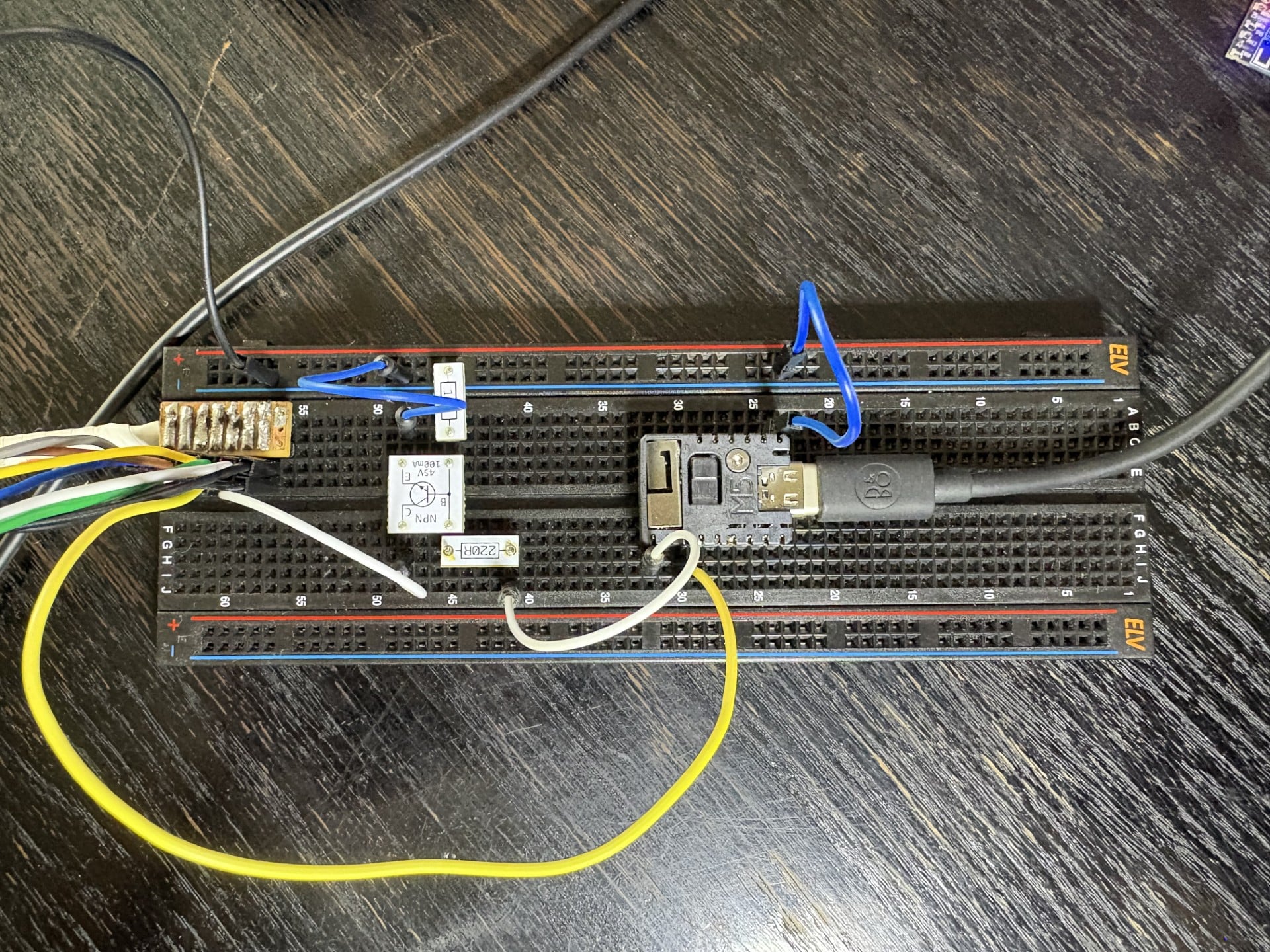
Simple, two things needed — tie PL4 to +5V, and send 0011000111100111111100000000100 on PL6 / PL7.With display
It gets more complicated — two additional requirements:
Mute BL Pin4 must only go HIGH after that init sequence (0011000111100111111100000000100) has finished sending — it has to stay LOW for the whole duration of the sequence.⚠️Remark : Sending PL commands to BL3500 its different than usual PL commands:
After the frame’s normal Stop (t4), one more t1 pulse (3.125ms) is required!During dev Beolab3500MKII_PL i recognize that the additional t1 in only needed for the init sequence. All other PL commands are as usual
23 August 2026 at 21:49 #125162swoGOLD Member
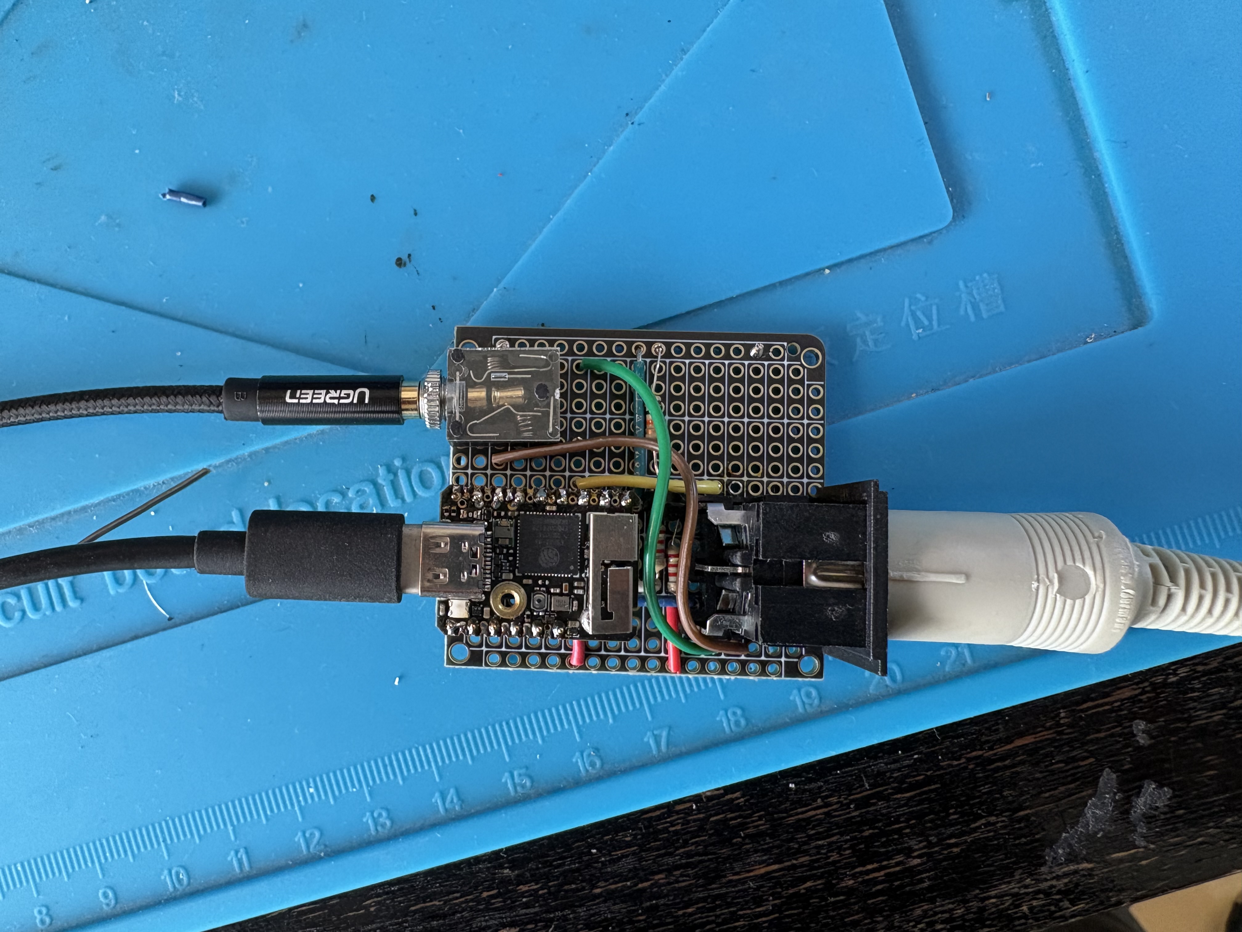
Made the first Beolab 3500 MK1 (MCL) standalone
23 August 2026 at 21:51 #125163Klaus StoetzelBRONZE MemberCongrats!
24 August 2026 at 08:30 #125166swoGOLD Member@Klaus thanks
and
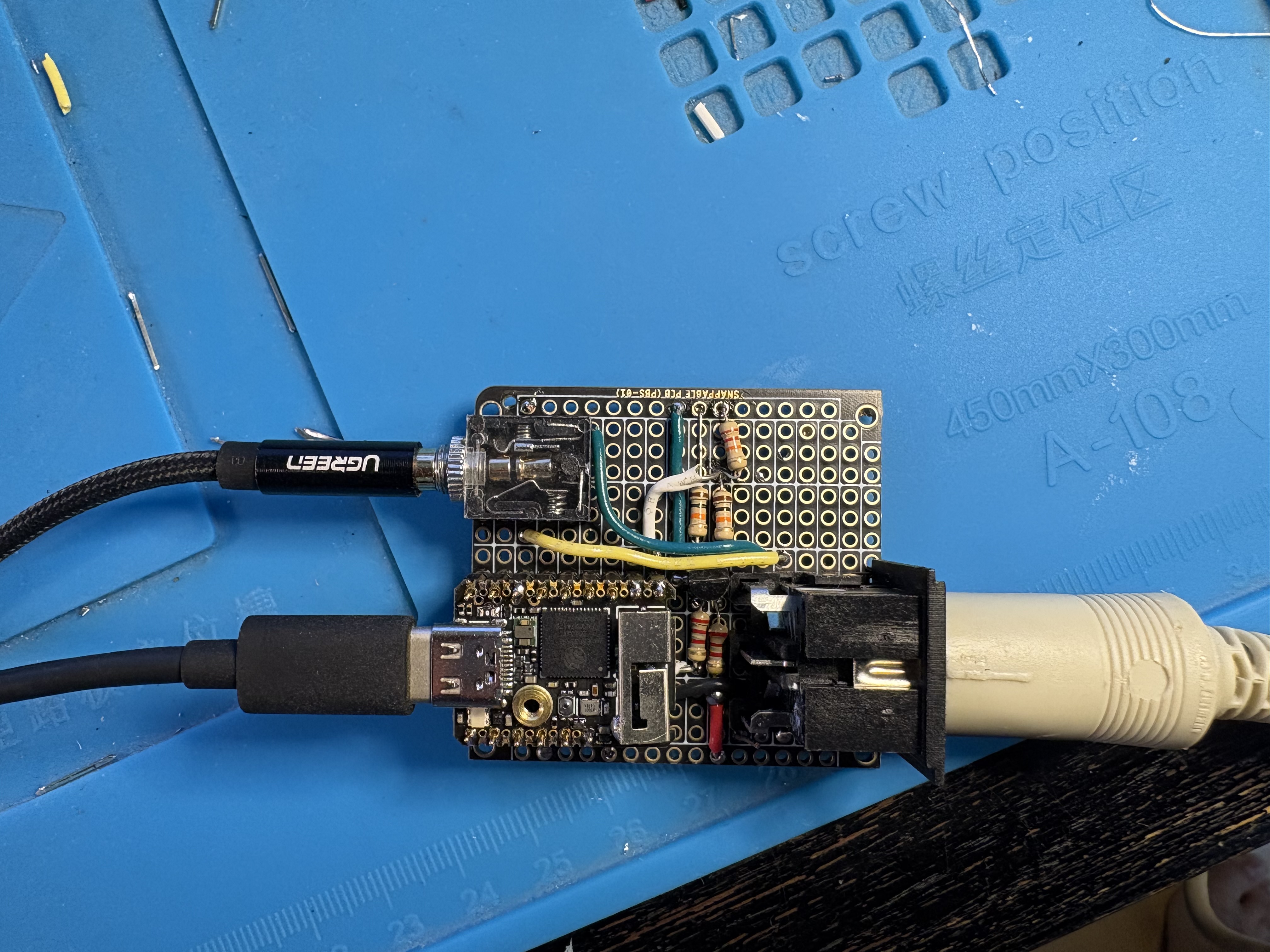
Made the first Beolab 3500 MK2 (PL) standalone
looks the same than the MK1 🙂 but it isn’t
-
This reply was modified 1 month, 4 weeks ago by swo.
24 August 2026 at 09:23 #125168MadskpGOLD MemberFirst of, very nice with these relatively simple solutions for making the BL3500 works as stand alone speaker 🙂 Might have to try that out when I have some spare time.
A little comment to your earlier statement:
When the Beolab 3500 Mk II is in PL mode, it behaves like a normal BL speaker (BL6000, BL8000): no IR reception, no SelectSource, and also no Vol+/Vol-. A speaker like that having its own display doesn’t really make sense in the first place.
Just to clarify from my own and other peoples testing the BL3500 MK II can only work as a normal Powerlink speaker when used with a Beolink Wireless 1 which send the correct signal to wake it up. I have not been successful at getting the BL3500 MK II going with other Powerlink sources.
Location: Denmark
24 August 2026 at 10:42 #125185swoGOLD MemberJust to clarify from my own and other peoples testing the BL3500 MK II can only work as a normal Powerlink speaker when used with a Beolink Wireless 1 which send the correct signal to wake it up. I have not been successful at getting the BL3500 MK II going with other Powerlink sources.
Yes, and the device (ESP32) does exactly the same as the BeoLink Wireless 1. See the post: https://forum.beoworld.org/forums/topic/bl3500-and-the-mcl-pl-connector/page/8/#post-125117.
What I wanted to point out with that post was that with the MK1 you have volume control / source selection, but with the MK2 you don’t — just like with the BeoLab 6000.
BR
24 August 2026 at 11:51 #125197MadskpGOLD MemberWhat I wanted to point out with that post was that with the MK1 you have volume control / source selection, but with the MK2 you don’t — just like with the BeoLab 6000.
That makes sense. One can only wonder why B&O choose to make the “complicated” activation of the MK II via the Powerlink connecter instead of just using the 5V power on signal like other Beolabs. My best guess is the B&O only needed to redesign the Plug and Crossfield PCB and could leave the rest of the internals of the BL3500 like the MK I.
Location: Denmark
25 August 2026 at 07:59 #125203TKBRONZE Member0011000111100111111100000000100
This is a curious command. If I’m decoding it correctly, this reads as follows:
00:1100:01111:0011:1111:1000:0000:0100, or “Send to ‘All’ an ‘AND’ command with N-Count of 4” + data. ‘N-Count of 4’ is a reserved command space listed as dedicated IR test data in the original specification for Datalink. Perhaps it has some other benefits in this scenario.
25 August 2026 at 08:13 #125205swoGOLD Member0011000111100111111100000000100
It looks like this is a secret between Beolink Wireless 1 and Beolink 3500 MK2 (also the additional t1 after t4) sorry i forgot this in the description above (will change)
25 August 2026 at 08:27 #125207swoGOLD MemberMadskp wrote:
Just to clarify from my own and other peoples testing the BL3500 MK II can only work as a normal Powerlink speaker when used with a Beolink Wireless 1 which send the correct signal to wake it up. I have not been successful at getting the BL3500 MK II going with other Powerlink sources.That brings me to one more use case.
If I connect the MK2 version of this project between a Powerlink source and the BL3500, and PIN 4 (5 V+) is enough to power the ESP32, I can transform a BL3500 into a normal Powerlink speaker. just send the init sequence to BL3500 when ESP32 boot. (and it boots every time Pin4 gets +5v 🙂 will test it soon25 August 2026 at 08:46 #125210MadskpGOLD MemberThat brings me to one more use case.
If I connect the MK2 version of this project between a Powerlink source and the BL3500, and PIN 4 (5 V+) is enough to power the ESP32, I can transform a BL3500 into a normal Powerlink speaker. just send the init sequence to BL3500 when ESP32 boot. (and it boots every time Pin4 gets +5v 🙂 will test it soonThat could be usefull for some pepople. There have from time to time been questions on the forum on how to use the BL3500 as a center speaker for a TV where that solution could be used
Location: Denmark
25 August 2026 at 14:53 #125214swoGOLD MemberThat could be usefull for some pepople. There have from time to time been questions on the forum on how to use the BL3500 as a center speaker for a TV where that solution could be used
Unfortunately the PL power lines (Pin 1 and Pin 4) don’t provide enough current. However, with an external 5 V supply it becomes feasible.
Of course the code must be adapted — but I streamlined it so it’s now under 100 lines.
/*BeoLab3500_MKII-PowerlinkMinimal trigger board for a Beolab 3500 MKII on the B&O PL bus:hold GPIO5 HIGH and it sends the captured MKII power-on/init frameonce on GPIO1 – nothing else. No RX, no MK1 support, no othercommands. Split out of Beolab3500-Standalone’s MclBusWriter (seewolfgangschneider/Beolab3500-Standalone ) – only sendInit() isneeded here, so it’s inlined directly instead of pulling in thewhole class/enum/MclData hierarchy.Per B&O MCL-2 Service Manual (“Datalink ’86”): the transmitting unitpulls the bus LOW for a fixed strobe width then releases it; thetiming symbol (t1..t5) is the FULL period (LOW+HIGH), not the LOWwidth alone. t1=3.125ms t2=6.250ms t3=9.375ms (data), t4=12.500ms(Stop), t5=15.625ms (Start). MKII traffic has one extra trailing t1pulse after Stop.*/#include <Arduino.h>constexpr gpio_num_t TX_PIN = GPIO_NUM_1;constexpr gpio_num_t TRIGGER_PIN = GPIO_NUM_5;constexpr uint32_t T1_US = 3125;constexpr uint32_t T2_US = 6250;constexpr uint32_t T3_US = 9375;constexpr uint32_t T4_US = 12500; // Stopconstexpr uint32_t T5_US = 15625; // Startconstexpr uint32_t STROBE_LOW_US = 1562;// Captured MKII power-on frame (Command=49, unrecognized/literal –// see Beolab3500-Standalone’s main.cpp file header for context).constexpr const char *INIT_BITS = “0011000111100111111100000000100”;void pulse(uint8_t tcode) {uint32_t period = tcode == 1 ? T1_US : tcode == 2 ? T2_US : tcode == 3 ? T3_US : tcode == 4 ? T4_US : T5_US;digitalWrite(TX_PIN, HIGH); // transistor on -> bus pulled lowdelayMicroseconds(STROBE_LOW_US);digitalWrite(TX_PIN, LOW); // transistor off -> bus released, pull-up brings it back highdelayMicroseconds(period – STROBE_LOW_US);}// which timing symbol encodesbitgiven the previous bit (differential code)uint8_t encodeBit(int lastBit, int bit) {if (lastBit == 0) return bit ? 3 : 2;return bit ? 2 : 1;}void sendInit() {Serial.println(“-> sending init”);int lastBit = 1; // Start acts as an implicit “1” referencepulse(1); // AGCpulse(1); // AGCpulse(5); // Startfor (size_t i = 0; INIT_BITS[i] != ‘\0’; i++) {int bit = INIT_BITS[i] – ‘0’;pulse(encodeBit(lastBit, bit));lastBit = bit;}pulse(4); // Stoppulse(1); // MKII trailing pulse}void setup() {Serial.begin(115200);delay(500);Serial.println(“BeoLab3500_MKII-Powerlink”);pinMode(TX_PIN, OUTPUT);digitalWrite(TX_PIN, LOW); // idle: transistor off, bus releasedpinMode(TRIGGER_PIN, INPUT_PULLDOWN);}void loop() {static bool wasHigh = false;bool nowHigh = digitalRead(TRIGGER_PIN) == HIGH;if (nowHigh && !wasHigh)sendInit(); // edge-triggered – one send per LOW->HIGH transition, not a flood while held highwasHigh = nowHigh;}-
This reply was modified 1 month, 3 weeks ago by swo.
25 August 2026 at 18:18 #125220swoGOLD MemberUnfortunately the PL power lines (Pin 1 and Pin 4) don’t provide enough current. However, with an external 5 V supply it becomes feasible.
This is only true for my current microcontroller, the ESP32‑S2. There are other boards with lower power consumption, such as the Digispark (ATtiny85).
-
This reply was modified 1 month, 3 weeks ago by swo.
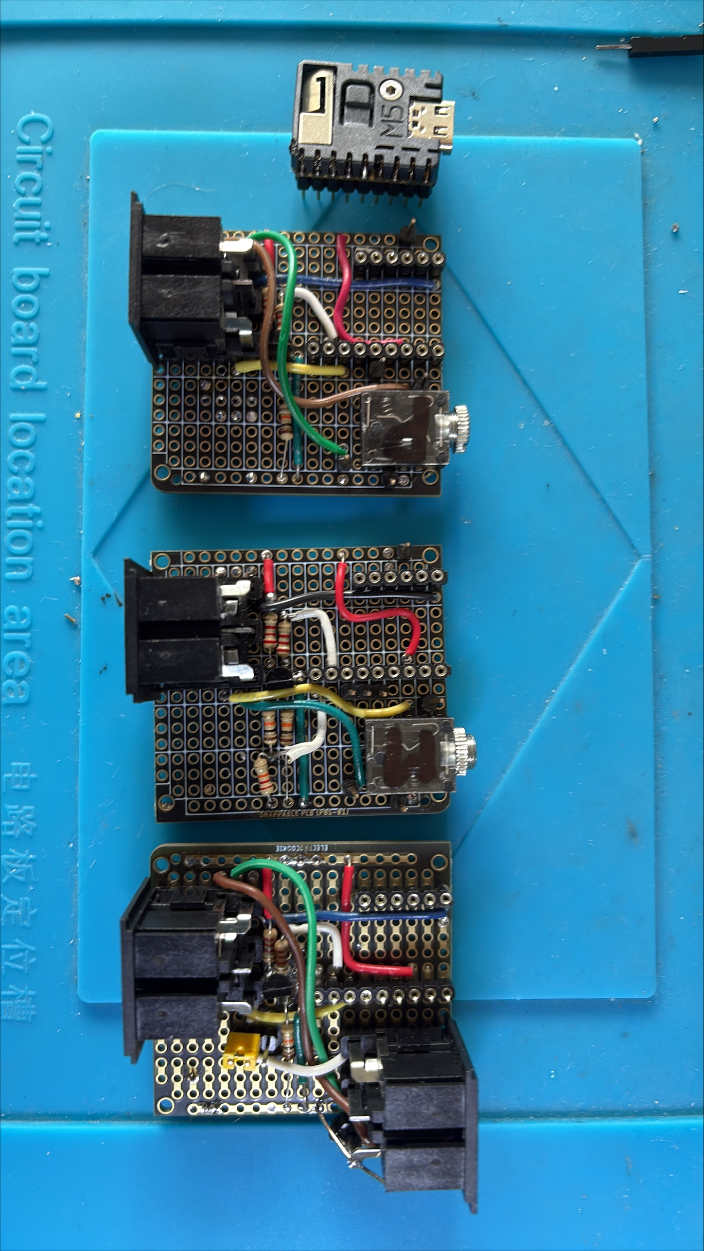
27 August 2026 at 08:32 #125257swoGOLD MemberAll 3 variantsPL → MK2 Aux ⇒ MK1 Aux → MK2
In case the PL ⇒ MK2 implementation does not fit into the current wolfgangschneider/Beolab3500-Standalone source, I will create its own GitHub repository.
-
This reply was modified 1 month, 3 weeks ago by swo.
5 September 2026 at 17:49 #125397MadskpGOLD MemberAll 3 variants
PL → MK2 Aux ⇒ MK1 Aux → MK2
In case the PL ⇒ MK2 implementation does not fit into the current wolfgangschneider/Beolab3500-Standalone source, I will create its own GitHub repository.
Just a little followup question for these wonderfull solutions that I have yet to find the time to try.
have you tried if any of them work when ML is ON in the MENU+0+9+GO setting?
if so this could be a great way to utilize an extra input on the Bl3500 while keeping it in a Masterlink setup.
Location: Denmark
6 September 2026 at 07:41 #125399swoGOLD Memberhave you tried if any of them work when ML is ON in the MENU+0+9+GO setting?
if so this could be a great way to utilize an extra input on the Bl3500 while keeping it in a Masterlink setup.
I didn’t try out , it seams that the MK1 must not set to “ML No” to open the MCL port.
However if you want an additional local source on BL3500 connected to a ML net, I suggest to use an Beolink Active using the PC plug. You get Beolink Active sometimes for 20€ ( have in mind the PC plug has uniq pin connection) -
This reply was modified 1 month, 4 weeks ago by
-
AuthorPosts
- You must be logged in to reply to this topic.